
This post contains affiliate links, marked with *. As an Amazon Associate I earn from qualifying purchases, at no extra cost to you. It helps keep the tutorials free.

The video loads from YouTube (Google), which may set cookies. Privacy policy
📋 ملخص سريع
Build OmObiArm — a Bluetooth-controlled mobile robot with an integrated 6-DOF (5+1 gripper) robotic arm powered by Arduino Mega, HC-05, Adafruit Motor Shield, and PCA9685 servo driver. This tutorial covers the complete build process: 3D printed chassis and arm design, dual motor driving, servo arm control, and smartphone Bluetooth control via MIT App Inventor.
تريد بناء روبوت متنقل يمكنه القيادة و pick things up? In this tutorial, you will build أوموبي أرم، يتم التحكم فيها عن طريق البلوتوث ذراع الروبوت المحمول مدعوم من أردوينو. OmObiArm pairs a four-wheel rover base with a 6-DOF robotic arm, all controlled wirelessly from a custom Android app through an HC-05 بلوتوث وحدة. خلال هذا المشروع، ستتعلم أيضًا كيفية تصميم الهيكل وتجميع الميكانيكا وتوصيل أسلاك Adafruit Motor Shield و محرك سيرفو PCA9685وبرمجة Arduino وإنشاء تطبيق تحكم باستخدام MIT App Inventor. في النهاية، سيكون لديك عمل DIY ذراع الروبوت المحمول يمكنها القيادة والوصول والإمساك وإعادة تشغيل وضعيات الذراع المحفوظة من تلقاء نفسها.
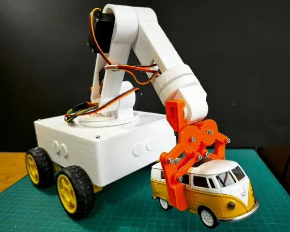
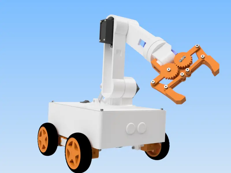
أوموبي أرم هو مشروع تمت ترقيته يجمع بين اثنين من بنياتنا السابقة: أوموبي، الروبوت المحمول الذي يتم التحكم فيه عن طريق البلوتوثو أومارم، الذراع الروبوتية 6-DOF مع التحكم عبر البلوتوث. بمجرد تثبيته على منصته المحمولة، يمكن لـ OmObiArm القيادة في جميع الاتجاهات بينما يمكنك التحكم بشكل مستقل في ستة مفاصل للذراع من خلال أشرطة التمرير في التطبيق. بالإضافة إلى ذلك، يقوم زر "حفظ" بتسجيل مواضع الذراع، ويقوم زر "تشغيل" بإعادة تشغيلها كتسلسلات تلقائية. لذا، إذا كنت تريد تعلم الميكاترونكس، أو منطق الأتمتة، أو التحكم في الروبوت اللاسلكي عبر البلوتوث، فهذا مشروع قوي يمكنك تجربته.
ما ستتعلمه
- كيف أوموبي أرم يجمع بين إمكانية التنقل في العربة الجوالة والتلاعب بالذراع الآلي في منصة واحدة يتم التحكم فيها بواسطة Arduino.
- كيف درع المحرك Adafruit Motor Shield V1.2 يقوم بتشغيل أربعة محركات تعمل بالتيار المستمر لحركة شاملة الاتجاهات لقاعدة الهاتف المحمول.
- كيف محرك سيرفو PCA9685 يتحكم في ستة أجهزة (ثلاثة MG996R وثلاثة SG90) للتحكم الدقيق في الذراع والقابض.
- كيف وحدة البلوتوث HC-05 يتيح الاتصال اللاسلكي بين هاتف Android الخاص بك وArduino.
- كيفية حفظ أوضاع الذراع وتشغيلها وتكرارها وإعادة ضبطها لتسلسلات المهام الآلية.
- كيفية إنشاء تطبيق للتحكم في Android باستخدام مخترع تطبيقات معهد ماساتشوستس للتكنولوجيا مع أشرطة التمرير والأزرار ومنطق البلوتوث.
- كيفية اختبار النظام بأكمله ومعايرته واستكشاف أخطائه وإصلاحها بما في ذلك الطاقة والماكينات والمحركات واتصال Bluetooth.
كيف يعمل أوموبيآرم
قبل البدء في البناء، من المفيد أن تفهم كيف يتناسب كل شيء معًا. باختصار، يستخدم OmObiArm أردوينو ميجا 2560 as its central controller. The Arduino receives Bluetooth commands from your phone through the وحدة HC-05 connected on the hardware serial pins (TX/RX on pins 0 and 1). Based on the received command string, it either drives the rover or moves the robotic arm.
ل حركة روفر، ثم يرسل Arduino الأوامر إلى درع المحرك Adafruit Motor Shield V1.2، والتي تتحكم في أربعة محركات DC من خلال محركات L293D المزدوجة H-bridge المدمجة. في الواقع، يقع درع المحرك مباشرة فوق Arduino Mega. إذا كنت تريد المزيد من التفاصيل حول كيفية عمل دروع المحركات، راجع موقعنا سيارة روبوت يتم التحكم فيها عن طريق البلوتوث مع البرنامج التعليمي Adafruit Motor Shield.
التحكم في الذراع والاتصالات اللاسلكية
وفي الوقت نفسه، ل التحكم في الذراع، يتواصل الاردوينو مع PCA9685 برنامج تشغيل مؤازر ذو 16 قناة over I2C. The PCA9685 generates PWM signals for six servos spread across channels 0, 4, 8, 9, 12, and 13. Of these, three MG996R servos handle the heavy base, shoulder and elbow joints, while three SG90 micro servos handle the lighter wrist and gripper joints. The PCA9685 gets its power independently through an LM2596 محول باك (a small adjustable DC-DC step-down module) that steps down the main 7.4 V LiPo battery to 6 V. This keeps the Arduino’s onboard regulator from being overloaded. To learn more about servo control with the PCA9685, see our دليل التحكم في المحرك المؤازر Arduino.
وفي الوقت نفسه، تطبيق التحكم للاندرويد (built with MIT App Inventor) sends single-character commands for rover movement (F, B, L, R, S) and formatted servo commands (for example, “1,90” to move servo 1 to 90 degrees) over Bluetooth. The app also sends pose management commands: “v” to save, “l” to play, “r” to reset, “s” to stop, “o” to enable loop, and “f” to disable loop. While poses are playing back, the rover motors stop automatically so the robot does not drive off unexpectedly. To learn more about the HC-05 module, visit our البرنامج التعليمي الكامل لوحدة البلوتوث HC-05/HC-06.
المكونات اللازمة لذراع الروبوت المحمول OmObiArm
To build the OmObiArm, you will need 3D printed parts from both the أوموبي روفر و الذراع الروبوتية OmArm، بالإضافة إلى الأجهزة الإلكترونية والمحركات والأجهزة التالية. يسرد جدول فاتورة المواد (BOM) الكامل أدناه كل جزء مطلوب بالإضافة إلى كميته والغرض منه.
ملخص المكونات الرئيسية
| فئة | عناصر |
|---|---|
| المراقب المالي | أردوينو ميجا 2560 |
| سائق موتور | Adafruit Motor Shield V1.2 (المعتمد على L293D) |
| سائق سيرفو | PCA9685 برنامج تشغيل مؤازر I2C ذو 16 قناة |
| بلوتوث | وحدة البلوتوث HC-05 |
| المحركات | 4 محركات DC مع علب التروس + 4 عجلات |
| الماكينات | 3 MG996R (عزم الدوران العالي) + 3 SG90 (ميكرو) |
| الطاقة | بطارية ليبو 7.4 فولت 2S (5300 مللي أمبير) + محول باك LM2596 (متدرج إلى 6 فولت) + مفتاح الطاقة |
| 3D Printed Parts | الهيكل، وصلات الذراع، المقبض، القاعدة، الأغطية، حامل Arduino (من تصميمات OmObi وOmArm) |
| الإكسسوارات | أسلاك توصيل، براغي M3، إدخالات، براغي M2، زنبرك تمديد، دبوس مشترك، محمل كروي (6806ZZ 30x42x7)، أبواق مؤازرة |
قائمة المواد الكاملة (BOM)
The following table is the complete bill of materials for the OmObiArm project. It also covers all 3D printed structural parts, servos, electronics, fasteners, and accessories. You can download items marked as “3D printed” as STL files from Cults3D أو الحصول عليها من لدينا متجر أومارترونيكس.
قائمة الأجزاء الكاملة
| البند | الكمية | الجزء | الغرض / ملاحظات |
|---|---|---|---|
| 1 | 1 | القاعدة السفلية (الهيكل) | قاعدة سفلية مطبوعة ثلاثية الأبعاد لتركيب المحركات والإلكترونيات |
| 2 | 1 | JIS B 1521 - 6806 JIS B 1521 - 6806 30x42x7 | محمل كروي ذو أخدود عميق لتدوير قاعدة الذراع |
| 3 | 1 | رابط الذراع 1 | وصلة الذراع الأولى المطبوعة ثلاثية الأبعاد |
| 4 | 1 | الإصبع القابض الأيمن | الإصبع الأيمن من القابض، مطبوع ثلاثي الأبعاد |
| 5 | 2 | غلاف القابض | جلبة بلاستيكية لمحور وصلة القابض |
| 6 | 1 | ترس القابض الأيمن | ترس الجانب الأيمن لآلية القابض |
| 7 | 1 | ترس القابض الأيسر | ترس الجانب الأيسر لآلية القابض |
| 8 | 1 | تجميع القابض | تجميع القابض الكامل المطبوع ثلاثي الأبعاد |
| 9 | 4 | الرابط | أجزاء الوصلة العامة، مطبوعة ثلاثية الأبعاد |
| 10 | 1 | قاعدة الذراع العلوية | جزء القاعدة العلوي المطبوع ثلاثي الأبعاد من الذراع الروبوتية |
| 11 | 3 | جهاز مؤازر صغير SG90 | مؤازرة مدمجة للمقبض والمفاصل خفيفة الوزن |
| 12 | 3 | مؤازر MG996R | مضاعفات عزم الدوران العالي للمفاصل الأساسية والثقيلة |
| 13 | 1 | رابط الذراع 3 | وصلة الذراع الثالثة المطبوعة ثلاثية الأبعاد |
| 14 | 1 | رابط الذراع 2 | وصلة الذراع الثانية المطبوعة ثلاثية الأبعاد |
| 15 | 1 | وصلة قاعدة الذراع | قاعدة مطبوعة ثلاثية الأبعاد لتوصيل الذراع الآلية بالمركبة الجوالة |
| 16 | 7 | AS 1420 - 1973 - M3 x 16 | برغي سداسي الرأس سداسي المقبس |
| 17 | 1 | زنبرك التمديد | زنبرك لشد الوصلة |
| 18 | 1 | دبوس مشترك | دبوس يستخدم لتثبيت المفاصل في الذراع الروبوتية |
| 19 | 1 | ANSI B18.2.4.4.2M - M3x0.5 | صامولة سداسية (لولب متري قياسي) |
| 20 | 3 | بوق MG955 | أبواق مؤازرة لمضاعفات الماكينات MG996R |
| 21 | 3 | بوق مؤازر SG90 | أبواق لمخدمات SG90 |
| 22 | 8 | المعيار ANSI B18.6.4 - رقم 3 - 28 - 1/2 | برغي التنصت على رأس الجمالون المتقاطع – النوع AB – النوع I |
| 23 | 16 | معيار ANSI B18.6.4 - رقم 2 - 32 - 3/8 | برغي التنصت على رأس الجمالون المتقاطع – النوع AB – النوع I |
السحابات والإلكترونيات وأجزاء الهيكل
| البند | الكمية | الجزء | الغرض / ملاحظات |
|---|---|---|---|
| 24 | 2 | معيار DIN 7985 (Z) - M3x6-Z | براغي برأس جبن بارزة متقاطعة الغائرة - النوع Z |
| 25 | 3 | معيار DIN 7985 (Z) - M2x6-Z | براغي برأس جبن بارزة متقاطعة الغائرة - النوع Z |
| 26 | 4 | ترس المحرك | ترس بلاستيكي لعمود محرك التيار المستمر |
| 27 | 4 | إطارات 4WD 4WD | عجلة مطاطية للقاعدة المتحركة |
| 28 | 4 | عجلة العربة ذات الدفع الرباعي 4WD | عجلة بلاستيكية لمنصة الدفع الرباعي |
| 29 | 1 | إطار الهيكل | إطار هيكل مطبوع ثلاثي الأبعاد للهيكل للدعم الهيكلي |
| 30 | 3 | الغلاف | أغطية مطبوعة ثلاثية الأبعاد |
| 31 | 1 | قاعدة سيارة روبوت | قاعدة مطبوعة ثلاثية الأبعاد |
| 32 | 1 | أردوينو ميجا 2560 | متحكم دقيق للتحكم والاتصال عبر البلوتوث |
| 33 | 1 | برنامج تشغيل المحرك L293D (Adafruit Motor Shield V1.2) | درع محرك H-bridge مزدوج للتحكم في محرك DC |
| 34 | 1 | بطارية ليبو 7.4 فولت 2S (5300 مللي أمبير) | مصدر الطاقة الرئيسي للنظام بأكمله |
| 35 | 16 | إدخالات M3 | إدراجات حرارية ملولبة للأجزاء المطبوعة ثلاثية الأبعاد |
| 36 | 1 | التبديل | مفتاح التشغيل/إيقاف التشغيل للدائرة الرئيسية |
| 37 | 16 | AS 1420 - 1973 - M3 x 6 - 1973 | براغي سداسية الرأس سداسية الشكل سداسية الرأس متري ISO |
| 38 | 4 | ANSI B18.3.3.1M - M3x0.5 × 30 | برغي غطاء رأس المقبس المطروق - متري |
| 39 | 4 | ANSI B18.3.3.1M - M3x0.5 × 25 | برغي غطاء رأس المقبس المطروق - متري |
| 40 | 1 | وحدة البلوتوث HC-05 | وحدة اتصالات لاسلكية للتحكم بالبلوتوث |
| 41 | 4 | معيار ANSI B18.6.4 - رقم 0 - 48 - 1/4 | برغي التنصت على رأس الجمالون المتقاطع – النوع AB – النوع I |
| 42 | 1 | محول LM2596 باك LM2596 | محول تنحي DC-DC لتزويد 6 فولت إلى PCA9685 |
| 43 | 1 | برنامج تشغيل المؤازر PCA9685 | لوحة تشغيل مؤازرة ذات 16 قناة تعتمد على I2C |
| 44 | 4 | محرك DC مع علبة التروس | محركات DC موجهة لقاعدة روفر 4WD |
الخطوة 1: تصميم نموذج OmObiArm ثلاثي الأبعاد لذراع الروبوت المتحرك
في البداية، تجمع هذه الخطوة بين التصاميم السابقة أوموبي روفر و الذراع الروبوتية OmArm projects. Using Autodesk Inventor, we modified the OmArm base and merged it with the top plate (lid) design from the OmObi. The result is a platform that securely mounts the robotic arm onto the mobile chassis. If you are new to 3D design for robotics, see our مقدمة للطباعة ثلاثية الأبعاد وAutodesk Inventor الدليل.
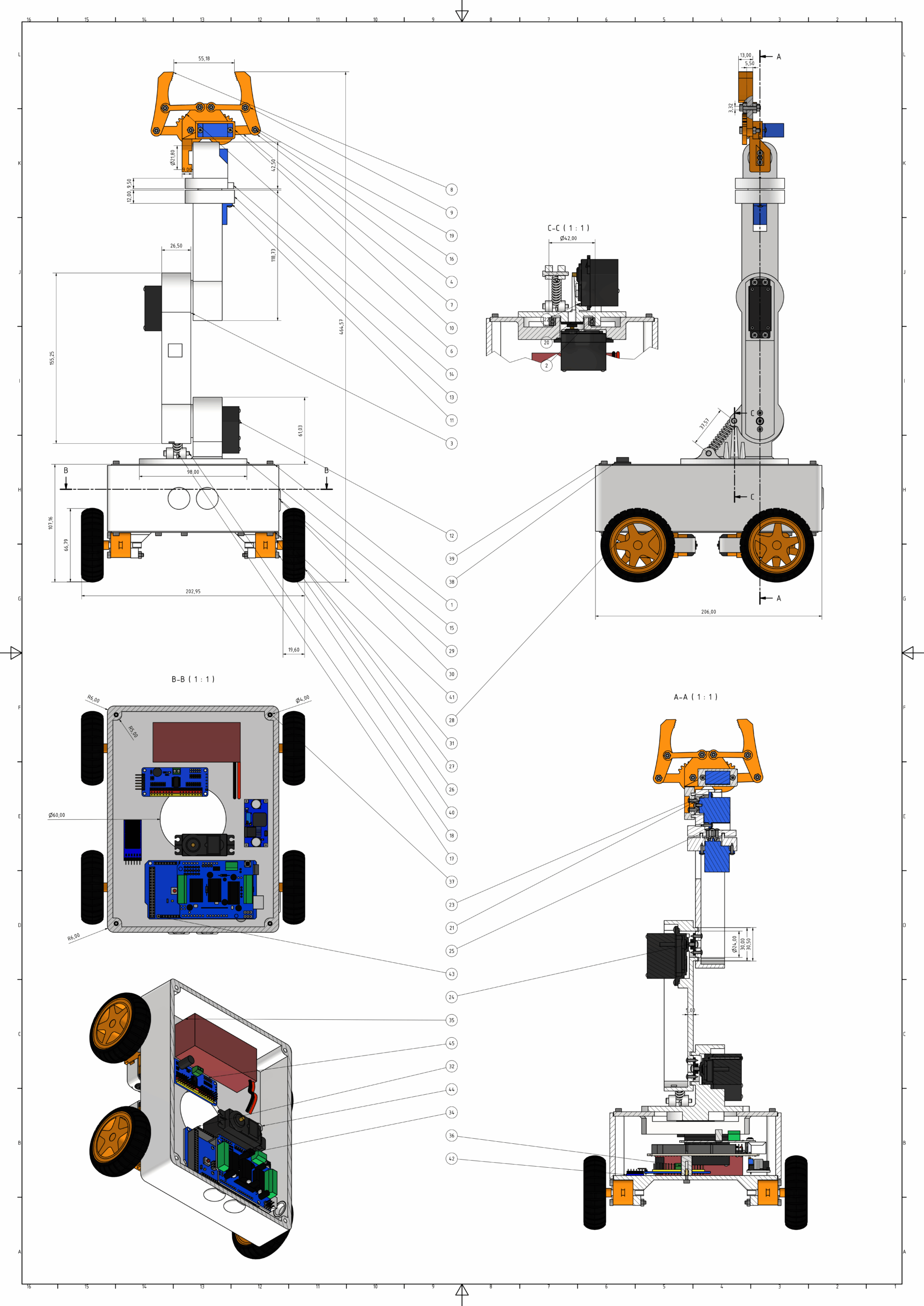
يمكنك تنزيل ملفات STL للطباعة ثلاثية الأبعاد من Cults3D أو من لدينا متجر أومارترونيكس. للمساعدة في التجميع، قمنا بتصميم جميع المكونات بأبعاد تفصيلية، والتي يمكنك رؤيتها في الرسم الفني أدناه. بالإضافة إلى ذلك، يتضمن الرسم مناظر مقطعية حتى تتمكن من الحصول على صورة واضحة للتصميم الميكانيكي وتخطيط التجميع.
الخطوة 2: الطباعة ثلاثية الأبعاد للأجزاء الروبوتية
After finalizing the design, 3D print all the components. For example, using a 3D printer like the Creality Ender 3, print all the parts listed in the BOM for both the robotic arm and the mobile platform. Generally, PLA filament works well for most parts. We also designed these parts to be easy to assemble and sturdy enough for regular use. For tips on printer settings and material selection, see our مقدمة للطباعة ثلاثية الأبعاد برنامج تعليمي.
الخطوة 3: تجميع روبوت OmObiArm
Once all the 3D printed parts are ready, it is time to assemble the OmObiArm mobile robot arm. Follow each sub-step carefully and verify fit and alignment before tightening screws.
3.1 تركيب المحركات والعجلات
قم بتوصيل المحركات: Secure the four DC motors to the 3D printed motor mounts using screws, inserts, and nuts. Make sure they are firmly attached to prevent any misalignment during movement.
قم بتركيب العجلات: قم بتوصيل العجلات بأعمدة المحرك وتأكد من تثبيتها بإحكام. اختبر سلاسة الدوران والمحاذاة المناسبة.
3.2 تركيب Arduino Mega وMotor Shield وPCA9685 وLM2596 وHC-05
وصِّل حامل الأردوينو: First, secure the 3D printed Arduino holder to the mobile chassis using screws.
تركيب الاردوينو وموتور شيلد: ضع أردوينو ميجا in the holder and secure it with screws. Attach the Adafruit Motor Shield on top of the Arduino Mega, making sure all pins are correctly aligned and seated.
ثم قم بإصلاح PCA9685 وLM2596 وHC-05: استخدم روابط مضغوطة أو شريط مزدوج الجوانب لتثبيت برنامج التشغيل المؤازر PCA9685، ومحول التنحي LM2596، ووحدة Bluetooth HC-05 على الهيكل. ضعها بحيث تكون مسارات الأسلاك قصيرة ومرتبة.
3.3 تثبيت اللوحة العلوية وقاعدة الذراع الآلية
Finally, attach the top plate (which is also the robotic arm base) onto the moving platform. Use screws to secure it firmly. As a result, this gives the robotic arm a stable mounting surface and prevents wobble during movement.
3.4 تجميع الذراع الروبوتية
الآن، تتبع مجموعة الذراع الآلية نفس الإجراء الموضح في موقعنا دليل بناء OmArm. لذلك اتبع هذه الخطوات الفرعية بعناية، حيث أن كل واحدة منها مبنية على السابقة:
الخطوة الفرعية 1 - تأمين محرك سيرفو على القاعدة: Install the first MG996R servo motor onto the robotic arm’s base using M3x12 screws. Add the 6806ZZ ball bearing (30x42x7 mm) to reduce friction and enable smooth rotation. Then attach the servo horn to the rotating upper part and secure it with M2x12 screws. Ensure the connection is tight and aligned.
الخطوة الفرعية 2 - تركيب الأبواق المؤازرة على روابط ذراع الروبوت: قم بمحاذاة أبواق المؤازرة مع نقاط ربط وصلات الذراع. قم بتثبيتها بالمسامير، وشدها بإحكام لمنع الانزلاق.
الخطوة الفرعية 3 - تركيب المحركات المؤازرة على وصلات الذراع: Align the servo motors with the mounting points on the arm links. Secure them using screws, and make sure the fit is tight and stable. Test the stability by gently moving the links.
الخطوة الفرعية 4 - توصيل روابط الذراع: قم بمحاذاة الوصلات وربطها باستخدام براغي من خلال قرون المؤازرة. تحقق مرة أخرى من أن الوصلات تتحرك بسلاسة ومثبتة بإحكام.
الخطوة الفرعية 5 - تجميع القابض: Finally, attach the gripper to the end link of the robotic arm using M3x20 screws. Verify that the gripper opens and closes smoothly and sits properly on the arm.
3.5 فحوصات التجميع النهائية
Once the robotic arm and mobile platform are fully assembled, test all components for stability and smooth operation. Make sure the motors, servos, and gripper all work correctly before moving on to wiring and programming.
الخطوة 4: توصيل مكونات OmObiArm
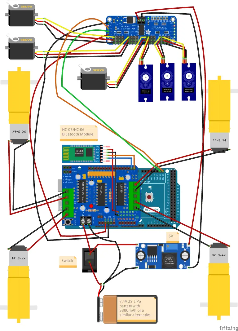
Getting the wiring right matters a lot for this project because bad connections can damage components or cause unpredictable behavior. The following sub-sections walk you through each connection group. Refer to the wiring diagram below for the complete circuit layout.
4.1 محركات التيار المستمر إلى درع المحرك
| المحرك | طرف توصيل درع المحرك | جانب |
|---|---|---|
| المحرك الأمامي الأيسر | M1 | غادر |
| المحرك الخلفي الأيسر | M2 | غادر |
| المحرك الأمامي الأيمن | M3 | يمين |
| المحرك الخلفي الأيمن | M4 | يمين |
First, attach the left-side motors to the terminals labeled M1 and M2 on the Adafruit Motor Shield, and the right-side motors to M3 and M4. Check the polarity so that all wheels spin in the right direction when a forward command is sent.
4.2 البطارية ومسار الطاقة الرئيسي
استخدم بطارية ليبو 7.4 فولت 2 ثانية بسعة لا تقل عن 5300 مللي أمبير وموصل EC3. قم بلحام قابس EC3 متوافق بمدخل الدائرة. أضف أ مفتاح الطاقة بين البطارية والدائرة للتحكم بسهولة في تدفق الطاقة. توفر البطارية الطاقة لكل من Adafruit Motor Shield (الذي يقوم بتشغيل Arduino من خلال المنظم الموجود على اللوحة) وبالتوازي مع محول باك LM2596.
4.3 LM2596 محول تنحى DC-DC
| LM2596 دبوس | الاتصال |
|---|---|
| في+ | البطارية إيجابية (7.4 فولت، عبر المفتاح) |
| في− | ارض البطارية |
| خارج + | محطة PCA9685 VCC (تم تعديلها إلى 6 فولت) |
| خارج− | محطة PCA9685 GND |
أولا، قم بتوصيل البطارية بالتوازي مع محول التنحي LM2596. قبل توصيل PCA9685، اضبط مقياس الجهد على LM2596 لضبط جهد الخرج تمامًا 6 خامسا باستخدام المتعدد. يعمل هذا المصدر المستقل بجهد 6 فولت على تشغيل لوحة التشغيل المؤازرة PCA9685 وجميع الماكينات المتصلة، مما يتجنب التحميل الزائد على منظم Arduino الموجود على اللوحة.
4.4 PCA9685 محرك المؤازرة والمؤازرة
| دبوس PCA9685 | الاتصال |
|---|---|
| VCC (محطة الطاقة) | مخرج LM2596 6 فولت |
| GND (محطة الطاقة) | مخرج LM2596 GND |
| SDA | اردوينو ميجا SDA (دبوس 20) |
| SCL | اردوينو ميجا SCL (دبوس 21) |
| VCC (المنطق) | أردوينو 5 فولت |
| جي إن دي (منطق) | شبكة GND للأردوينو |
Next, connect each servo to the appropriate PCA9685 channel, making sure the signal, VCC, and GND pins are aligned correctly. The servo channel assignments used in the code are:
| Servo | مشترك | قناة PCA9685 | يكتب |
|---|---|---|---|
| المؤازر 1 | دوران القاعدة | 0 | MG996R |
| المؤازرة 2 | كتف | 4 | MG996R |
| سيرفو 3 | مِرفَق | 8 | MG996R |
| سيرفو 4 | الملعب المعصم | 9 | SG90 |
| سيرفو 5 | لفة المعصم | 12 | SG90 |
| سيرفو 6 | القابض | 13 | SG90 |
Make sure you use the independent 6 V power source from the LM2596 for the PCA9685 servo power terminal. In other words, do not power the servos from the Arduino’s 5 V pin — this will cause voltage drops, servo jitter, and possible Arduino resets.
4.5 HC-05 وحدة بلوتوث
| دبوس HC-05 | اردوينو ميجا دبوس |
|---|---|
| VCC | 5 V |
| GND | GND |
| TXD | RX0 (دبوس 0) |
| RXD | TX0 (دبوس 1) |
ملاحظة هامة حول الدبابيس 0 و 1: يتصل HC-05 بالدبابيس التسلسلية لأجهزة Arduino Mega (Serial0، دبابيس 0 و1). نظرًا لأن هذه هي نفس المسامير التي يستخدمها اتصال USB لتحميل الرسومات، يمكنك يجب فصل HC-05 (or at least disconnect the HC-05 TXD wire from pin 0) before uploading code from the Arduino IDE. If you leave the HC-05 connected during upload, the upload will fail with a communication error. Reconnect the HC-05 afterwards. For a detailed guide on HC-05 wiring and pairing, see our البرنامج التعليمي لوحدة البلوتوث Arduino HC-05/HC-06.
4.6 Adafruit Motor Shield إلى Arduino Mega
Place the Adafruit Motor Shield securely onto the Arduino Mega, making sure all pins align and seat correctly. The Motor Shield piggybacks directly on top of the Arduino headers, so no additional wiring is needed between the shield and the Arduino — the shield communicates through the stacked pin headers. For more on how the Adafruit Motor Shield works, see our سيارة روبوت بلوتوث مع البرنامج التعليمي Adafruit Motor Shield.
4.7 اختبار توزيع الطاقة
Before powering on the system for the first time, check all power connections with a multimeter. Look for short circuits, and make sure the motors, servos, and HC-05 module are each getting the right voltage: the Arduino and HC-05 should see 5 V, the servos should see 6 V from the LM2596, and the motors should get the full battery voltage through the Motor Shield.
الخطوة 5: برمجة ذراع الروبوت المتنقل OmObiArm للتحكم بالبلوتوث
In this step, we program the Arduino Mega to control the robotic arm and the mobile platform over Bluetooth. The complete code handles Bluetooth command parsing, rover motor control, smooth servo movement, and pose save/play/loop logic. You can find the complete source code and the MIT App Inventor project file in the مستودع GitHub: التطبيق والرمز. إذا كنت جديدًا في برمجة Arduino، فننصحك بمراجعة موقعنا أساسيات برمجة الأردوينو البرنامج التعليمي أولا.
مهم: تذكر دائمًا فصل وحدة HC-05 عن الأطراف 0/1 قبل تحميل هذا المخطط. وبعد ذلك، أعد توصيله بعد اكتمال التحميل.
أكمل كود OmObiArm Arduino
#include <Wire.h>
#include <Adafruit_PWMServoDriver.h>
#include <AFMotor.h>

// Constants and definitions
const int numServos = 6; // Number of servos
const int maxConfigurations = 10; // Maximum number of storable poses
const int stepDelay = 10; // Delay between each step to slow down the servo movement
const int stepSize = 1;   // The number of degrees to move per step

// Servo channels on the PCA9685
const int servoChannels[numServos] = {0, 4, 8, 9, 12, 13};

// Storage structures
int savedConfigurations[maxConfigurations][numServos];
int currentServoPositions[numServos] = {375, 375, 375, 375, 375, 375}; // Default positions
int configCount = 0;            // Counter for stored poses
bool isPlaying = false;         // Status indicating if poses are being played
bool loopPlayback = false;      // Status indicating if poses should be played in a loop
bool stopPlaying = false;       // Status indicating if playback should be stopped
int currentPoseIndex = 0;       // Index of the current pose during playback

// Motor instances for the rover
AF_DCMotor motor1(1);
AF_DCMotor motor2(2);
AF_DCMotor motor3(3);
AF_DCMotor motor4(4);

Adafruit_PWMServoDriver pwm = Adafruit_PWMServoDriver();
String input = ""; // Holds incoming Bluetooth data

void setup() {
  Serial.begin(9600); // Serial communication for Bluetooth

  // Initialize motors
  motor1.setSpeed(255);
  motor2.setSpeed(255);
  motor3.setSpeed(255);
  motor4.setSpeed(255);

  // Initialize servo controller
  pwm.begin();
  pwm.setPWMFreq(50); // Set frequency to 50 Hz for servos

  // Initialize servo positions
  for (int i = 0; i < numServos; i++) {
    pwm.setPWM(servoChannels[i], 0, currentServoPositions[i]);
  }

  Serial.println("Bluetooth Robot Controller ready. Waiting for commands...");
}
الحلقة الرئيسية وكود معالجة الأوامر
void loop() {
  // Process incoming commands
  if (Serial.available()) {
    input = Serial.readStringUntil('\n'); // Read data from Bluetooth
    input.trim();

    Serial.println("Received command: " + input);
    processCommand(input);
  }

  // Check if robot arm is playing poses
  if (isPlaying && !stopPlaying) {
    if (loopPlayback) {
      playPosesInLoop();
    } else {
      playNextPose();
    }
  }
}
كود معالجة الأوامر
void processCommand(String command) {
  // If playing, ignore all rover commands
  if (isPlaying) {
    if (command == "s") { // Allow stop playback command
      stopPlayingPoses();
    } else {
      Serial.println("Playback in progress. Ignoring command: " + command);
    }
    return;
  }

  // Control rover movement
  if (command == "F") {
    forward();
  } else if (command == "B") {
    backward();
  } else if (command == "L") {
    turnLeft();
  } else if (command == "R") {
    turnRight();
  } else if (command == "S") {
    stopMotors(); // Stop motors immediately on "S" command

  // Control robotic arm
  } else if (command.startsWith("1,")) {
    processServoCommand(command, 0); // Control Servo 1
  } else if (command.startsWith("2,")) {
    processServoCommand(command, 1); // Control Servo 2
  } else if (command.startsWith("3,")) {
    processServoCommand(command, 2); // Control Servo 3
  } else if (command.startsWith("4,")) {
    processServoCommand(command, 3); // Control Servo 4
  } else if (command.startsWith("5,")) {
    processServoCommand(command, 4); // Control Servo 5
  } else if (command.startsWith("6,")) {
    processServoCommand(command, 5); // Control Servo 6

  // Save, play, reset poses
  } else if (command == "v") {
    saveCurrentPose();
  } else if (command == "l") {
    startPlayingPoses();
  } else if (command == "r") {
    resetPoses();
  } else if (command == "s") {
    stopPlayingPoses();
  } else if (command == "o") {
    loopPlayback = true;
    Serial.println("Loop playback enabled.");
  } else if (command == "f") {
    loopPlayback = false;
    Serial.println("Loop playback disabled.");
  } else {
    Serial.println("Unknown command: " + command);
  }
}

void processServoCommand(String command, int servoIndex) {
  int commaIndex = command.indexOf(',');
  if (commaIndex > 0) {
    int position = command.substring(commaIndex + 1).toInt();
    int pwmValue = map(position, 0, 180, 150, 600);
    moveToPositionSmoothly(servoIndex, pwmValue);
  }
}
التحكم في المحركات ووظائف الوضع
void forward() {
  motor1.run(FORWARD);
  motor2.run(FORWARD);
  motor3.run(FORWARD);
  motor4.run(FORWARD);
  Serial.println("Moving forward");
}

void backward() {
  motor1.run(BACKWARD);
  motor2.run(BACKWARD);
  motor3.run(BACKWARD);
  motor4.run(BACKWARD);
  Serial.println("Moving backward");
}

void turnLeft() {
  motor1.run(BACKWARD);
  motor2.run(BACKWARD);
  motor3.run(FORWARD);
  motor4.run(FORWARD);
  Serial.println("Turning left");
}

void turnRight() {
  motor1.run(FORWARD);
  motor2.run(FORWARD);
  motor3.run(BACKWARD);
  motor4.run(BACKWARD);
  Serial.println("Turning right");
}

void stopMotors() {
  motor1.run(RELEASE);
  motor2.run(RELEASE);
  motor3.run(RELEASE);
  motor4.run(RELEASE);
  Serial.println("Motors stopped");
}

// Arm servo control
void moveToPositionSmoothly(int servoIndex, int targetPwmValue) {
  int currentPwmValue = currentServoPositions[servoIndex];
  if (targetPwmValue > currentPwmValue) {
    for (int pos = currentPwmValue; pos <= targetPwmValue; pos += stepSize) {
      pwm.setPWM(servoChannels[servoIndex], 0, pos);
      delay(stepDelay);
    }
  } else {
    for (int pos = currentPwmValue; pos >= targetPwmValue; pos -= stepSize) {
      pwm.setPWM(servoChannels[servoIndex], 0, pos);
      delay(stepDelay);
    }
  }
  currentServoPositions[servoIndex] = targetPwmValue;
  Serial.println("Servo " + String(servoIndex + 1) + " set to position: " + String(targetPwmValue));
}
وظائف إدارة الوضع
void saveCurrentPose() {
  if (configCount < maxConfigurations) {
    for (int i = 0; i < numServos; i++) {
      savedConfigurations[configCount][i] = currentServoPositions[i];
    }
    configCount++;
    Serial.println("Pose saved. Total poses: " + String(configCount));
  } else {
    Serial.println("Memory full. Cannot save pose.");
  }
}

void startPlayingPoses() {
  if (configCount > 0) {
    stopMotors(); // Ensure rover is stopped during playback
    isPlaying = true;
    stopPlaying = false;
    currentPoseIndex = 0;
    Serial.println("Starting pose playback");
  } else {
    Serial.println("No poses saved");
  }
}

void playNextPose() {
  if (currentPoseIndex < configCount) {
    for (int i = 0; i < numServos; i++) {
      moveToPositionSmoothly(i, savedConfigurations[currentPoseIndex][i]);
    }
    delay(1000);
    currentPoseIndex++;
  } else {
    isPlaying = false;
    Serial.println("Pose playback finished");
  }
}

void playPosesInLoop() {
  for (int i = 0; i < configCount; i++) {
    if (stopPlaying) break; // Immediate stop on command
    for (int j = 0; j < numServos; j++) {
      moveToPositionSmoothly(j, savedConfigurations[i][j]);
    }
    delay(1000);
  }
}

void stopPlayingPoses() {
  stopPlaying = true;
  isPlaying = false;
  Serial.println("Pose playback stopped");
}

void resetPoses() {
  configCount = 0;
  isPlaying = false;
  loopPlayback = false;
  currentPoseIndex = 0;
  Serial.println("All poses reset");
}
إرشادات التعليمات البرمجية: المكتبات المضمنة
#include <Wire.h>
#include <Adafruit_PWMServoDriver.h>
#include <AFMotor.h>
أولاً، أنت بحاجة إلى ثلاث مكتبات لهذا المشروع. Wire.h يوفر اتصال I2C، والذي يستخدمه برنامج التشغيل المؤازر PCA9685 لتلقي الأوامر من Arduino. Adafruit_PWMServoDriver.h هي مكتبة للتحكم في الماكينات من خلال لوحة PCA9685. و AFMotor.h is the Adafruit Motor Shield library that simplifies DC motor control through the L293D H-bridges on the shield. Make sure all three are installed in your Arduino IDE before compiling.
إرشادات التعليمات البرمجية: تعيين قناة المؤازرة والمتغيرات
const int numServos = 6;
const int maxConfigurations = 10;
const int stepDelay = 10;
const int stepSize = 1;
const int servoChannels[numServos] = {0, 4, 8, 9, 12, 13};
int savedConfigurations[maxConfigurations][numServos];
int currentServoPositions[numServos] = {375, 375, 375, 375, 375, 375};
int configCount = 0;
bool isPlaying = false;
bool loopPlayback = false;
bool stopPlaying = false;
int currentPoseIndex = 0;
بعد ذلك، تحدد الثوابت معلمات النظام. numServos تم ضبطه على 6 لأن الذراع بها ستة مفاصل. التكوينات القصوى يحد من عدد الأوضاع المحفوظة إلى 10 (مخزنة في ذاكرة الوصول العشوائي). تأخير الخطوة (10 مللي ثانية) و حجم الخطوة (وحدة PWM واحدة) تتحكم في مدى سلاسة تحرك الماكينات. تنتج أحجام الخطوات الأصغر ذات التأخيرات القصيرة حركة سلسة بدلاً من القفزات المفاجئة. ال قنوات مؤازرة يقوم المصفوفة بتعيين كل أجهزة منطقية (من 1 إلى 6) لقناة PCA9685 الفعلية الخاصة بها (0، 4، 8، 9، 12، 13). ال currentServoPositions يتتبع المصفوفة مكان وجود كل مؤازرة حاليًا، باستخدام قيم PWM الأولية (375 هو النطاق المتوسط تقريبًا لتعيين 150 إلى 600 PWM). وأخيرا، الأعلام المنطقية هو اللعب, تكرار التشغيلو stopPlaying إدارة آلة الحالة لتشغيل الوضع.
إرشادات التعليمات البرمجية: تهيئة المحرك
AF_DCMotor motor1(1);
AF_DCMotor motor2(2);
AF_DCMotor motor3(3)؛ AF_DCMotor motor3(3);
AF_DCMotor motor4(4);
Adafruit_PWMServoDriver pwm = Adafruit_PWMServoDriver();
بعد ذلك، يتم إنشاء أربعة كائنات محرك DC على القنوات من 1 إلى 4 من Adafruit Motor Shield. ال Adafruit_PWMSMServoDriver كائن (يسمى pwm) تتم تهيئته بعنوان I2C الافتراضي (0x40) للوحة PCA9685. ومع ذلك، إذا كان لديك لوحات PCA9685 متعددة، فسوف تقوم بتمرير عنوان مختلف هنا.
إرشادات التعليمات البرمجية: وظيفة الإعداد
void setup() {
  Serial.begin(9600);
  motor1.setSpeed(255);
  motor2.setSpeed(255);
  motor3.setSpeed(255);
  motor4.setSpeed(255);
  pwm.begin();
  pwm.setPWMFreq(50);
  for (int i = 0; i < numServos; i++) {
    pwm.setPWM(servoChannels[i], 0, currentServoPositions[i]);
  }
}
أثناء بدء التشغيل، تقوم وظيفة الإعداد بتهيئة الاتصال التسلسلي عند 9600 باود, which must match the HC-05’s default baud rate. It then sets all four motors to maximum speed (255 out of 255), initializes the PCA9685 at a PWM frequency of 50 هرتز (المعيار لماكينات الهوايات)، وينقل جميع الماكينات الستة إلى مواضعها الافتراضية متوسطة المدى (قيمة PWM 375) بحيث يبدأ الذراع في وضع معروف وآمن.
إرشادات التعليمات البرمجية: تنسيق أمر Bluetooth ووظيفة الحلقة
void loop() {
  if (Serial.available()) {
    input = Serial.readStringUntil('\n');
    input.trim();
    processCommand(input);
  }
  if (isPlaying && !stopPlaying) {
    if (loopPlayback) {
      playPosesInLoop();
    } else {
      playNextPose();
    }
  }
}
الآن، تقوم الحلقة الرئيسية بالتحقق بشكل مستمر من بيانات البلوتوث الواردة على المنفذ التسلسلي. عندما تكون البيانات متاحة، فإنها تقرأ سلسلة أوامر كاملة حتى حرف السطر الجديد ('\n') استخدام قراءة السلسلة('\n'). لذا فإن السطر الجديد يعمل كمحدد للأمر، بحيث ينتهي كل أمر يتم إرساله من التطبيق بـ \n. بعد قطع المسافة البيضاء، تنتقل سلسلة الأمر إلى عملية الأمر (). وفي الوقت نفسه، يتحقق النصف الثاني من الحلقة مما إذا كان تشغيل الوضعية نشطًا، وإذا كان الأمر كذلك، فإنه إما يلعب الوضعيات في حلقة أو يتقدم إلى الوضع التالي بالتسلسل.
التعليمات البرمجية التفصيلية: معالجة الأوامر (Rover وArm)
void processCommand(String command) {
  if (isPlaying) {
    if (command == "s") { stopPlayingPoses(); }
    return;
  }
  if (command == "F") forward();
  else if (command == "B") backward();
  else if (command == "L") turnLeft();
  else if (command == "R") turnRight();
  else if (command == "S") stopMotors();
  else if (command.startsWith("1,")) processServoCommand(command, 0);
  else if (command.startsWith("2,")) processServoCommand(command, 1);
  else if (command.startsWith("3,")) processServoCommand(command, 2);
  else if (command.startsWith("4,")) processServoCommand(command, 3);
  else if (command.startsWith("5,")) processServoCommand(command, 4);
  else if (command.startsWith("6,")) processServoCommand(command, 5);
  else if (command == "v") saveCurrentPose();
  else if (command == "l") startPlayingPoses();
  else if (command == "r") resetPoses();
  else if (command == "s") stopPlayingPoses();
  else if (command == "o") { loopPlayback = true; }
  else if (command == "f") { loopPlayback = false; }
}
إن عملية الأمر () الوظيفة هي مرسل القيادة المركزية. يقوم أولاً بالتحقق مما إذا كان تشغيل الوضع نشطًا. إذا كان الأمر كذلك، فسيتم قبول الأمر "s" (الإيقاف) فقط ويتم تجاهل كافة الأوامر الأخرى. ونتيجة لذلك، يمنع هذا حركة العربة الجوالة أثناء تشغيل الذراع، مما قد يتسبب في تحرك الروبوت بشكل غير متوقع.
باختصار، بروتوكول الأوامر الكامل هو كما يلي:
مرجع قيادة روفر والذراع
| Command | فعل | فئة |
|---|---|---|
F | قيادة روفر إلى الأمام | روفر |
B | قيادة روفر إلى الوراء | روفر |
L | انعطف يسارًا | روفر |
R | اقلب العربة الجوالة إلى اليمين | روفر |
S | أوقف جميع محركات العربة الجوالة | روفر |
1، | انقل المؤازرة 1 (القاعدة) إلى الزاوية (0–180) | ذراع |
2، | انقل المؤازرة 2 (الكتف) إلى الزاوية | ذراع |
3، | حرك المؤازرة 3 (الكوع) إلى الزاوية | ذراع |
4، | حرك المؤازرة 4 (درجة المعصم) إلى الزاوية | ذراع |
5، | حرك المؤازرة 5 (لفة المعصم) إلى الزاوية | ذراع |
6، | انقل المؤازرة 6 (القابض) إلى الزاوية | ذراع |
v | حفظ وضعية الذراع الحالية | أَثَار |
l | ابدأ بلعب الأوضاع المحفوظة | أَثَار |
r | إعادة تعيين (مسح) جميع الأوضاع المحفوظة | أَثَار |
s | إيقاف التشغيل الوضعي | أَثَار |
o | تمكين وضع تشغيل الحلقة | أَثَار |
f | تعطيل وضع تشغيل الحلقة | أَثَار |
تنسيق الأوامر المؤازرة ومعالجتها
عند التحكم في الذراع، تستخدم أوامر المؤازرة التنسيق "ن، زاوية"، حيث N هو رقم المؤازرة (1–6) والزاوية هي الموضع بالدرجات (0–180). ال عمليةسيرفوكوماند () تقوم الوظيفة بتحليل هذه السلسلة، واستخراج قيمة الزاوية، وتعيينها من نطاق 0–180 درجة إلى نطاق PCA9685 PWM (150–600)، واستدعاء وظيفة الحركة السلسة.
إرشادات التعليمات البرمجية: وظائف التحكم في محرك Rover
void forward() {
  motor1.run(FORWARD); motor2.run(FORWARD);
  motor3.run(FORWARD); motor4.run(FORWARD);
}
void backward() {
  motor1.run(BACKWARD); motor2.run(BACKWARD);
  motor3.run(BACKWARD); motor4.run(BACKWARD);
}
void turnLeft() {
  motor1.run(BACKWARD); motor2.run(BACKWARD);
  motor3.run(FORWARD); motor4.run(FORWARD);
}
void turnRight() {
  motor1.run(FORWARD); motor2.run(FORWARD);
  motor3.run(BACKWARD); motor4.run(BACKWARD);
}
void stopMotors() {
  motor1.run(RELEASE); motor2.run(RELEASE);
  motor3.run(RELEASE); motor4.run(RELEASE);
}
بعد ذلك، تتحكم كل وظيفة حركة في جميع المحركات الأربعة في وقت واحد من خلال درع محرك Adafruit. بالنسبة للحركة للأمام والخلف، تدور المحركات الأربعة في نفس الاتجاه. من أجل الدوران، تعمل المحركات الموجودة على جانب واحد للأمام بينما يعمل الجانب الآخر للخلف (نمط التوجيه الانزلاقي / دوران الخزان). ال توقف المحركات () استخدامات الوظيفة يطلق to cut power to all motors. The motor speed is set to 255 (maximum) in setup; يمكنك خفض هذه القيمة إذا كنت تريد حركة أبطأ وأكثر تحكمًا. لإلقاء نظرة أعمق على التحكم في محرك التيار المستمر، راجع موقعنا البرنامج التعليمي لسائق المحرك L298N.
إرشادات التعليمات البرمجية: حركة مؤازرة سلسة
void moveToPositionSmoothly(int servoIndex, int targetPwmValue) {
  int currentPwmValue = currentServoPositions[servoIndex];
  if (targetPwmValue > currentPwmValue) {
    for (int pos = currentPwmValue; pos <= targetPwmValue; pos += stepSize) {
      pwm.setPWM(servoChannels[servoIndex], 0, pos);
      delay(stepDelay);
    }
  } else {
    for (int pos = currentPwmValue; pos >= targetPwmValue; pos -= stepSize) {
      pwm.setPWM(servoChannels[servoIndex], 0, pos);
      delay(stepDelay);
    }
  }
  currentServoPositions[servoIndex] = targetPwmValue;
}
Instead of jumping directly to the target position (which causes jerky movement and can damage gears), this function steps through intermediate PWM values one unit at a time with a 10 ms delay between steps. The loop direction (incrementing or decrementing) depends on whether the target is higher or lower than the current position. After the loop completes, the currentServoPositions array is updated so the system always knows where each servo actually is. Note that while smooth movement is active, the Arduino is blocked in the for-loop and cannot process new commands. This is intentional for the OmObiArm, but you could improve it with non-blocking approaches in a more advanced version. For more on servo fundamentals, see our دليل التحكم بمحرك سيرفو من Arduino لـ SG90 وPCA9685.
إرشادات التعليمات البرمجية: وضع الحفظ والتشغيل والتكرار وإعادة تعيين المنطق
void saveCurrentPose() {
  if (configCount < maxConfigurations) {
    for (int i = 0; i < numServos; i++) {
      savedConfigurations[configCount][i] = currentServoPositions[i];
    }
    configCount++;
  }
}
void startPlayingPoses() {
  if (configCount > 0) {
    stopMotors();
    isPlaying = true;
    stopPlaying = false;
    currentPoseIndex = 0;
  }
}
void playNextPose() {
  if (currentPoseIndex < configCount) {
    for (int i = 0; i < numServos; i++) {
      moveToPositionSmoothly(i, savedConfigurations[currentPoseIndex][i]);
    }
    delay(1000);
    currentPoseIndex++;
  } else {
    isPlaying = false;
  }
}
void playPosesInLoop() {
  for (int i = 0; i < configCount; i++) {
    if (stopPlaying) break;
    for (int j = 0; j < numServos; j++) {
      moveToPositionSmoothly(j, savedConfigurations[i][j]);
    }
    delay(1000);
  }
}
void resetPoses() {
  configCount = 0;
  isPlaying = false;
  loopPlayback = false;
  currentPoseIndex = 0;
}
كيفية عمل التسجيل والتشغيل
يسمح نظام الوضعية بتسجيل وإعادة تشغيل أوضاع الذراع. حفظCurrentPose() نسخ جميع قيم PWM المؤازرة الستة الحالية إلى ملف التكوينات المحفوظة قم بضبط العداد وزيادة عدده، بما يصل إلى 10 أوضاع كحد أقصى في المجمل. startPlayingPoses() يقوم أولاً بإيقاف محركات العربة الجوالة (لمنع الروبوت من القيادة أثناء تشغيل الذراع)، ثم يضبط إشارات التشغيل ويعيد ضبط مؤشر الوضعية على 0.
بلاينكستبوز () ينقل جميع الماكينات الستة إلى المواضع المخزنة في الوضع الحالي، وينتظر ثانية واحدة، ويتقدم إلى الوضع التالي. عند تشغيل جميع الأوضاع، يتوقف التشغيل تلقائيًا. بلايبوسينلوب () يتنقل بشكل مستمر عبر جميع الأوضاع المحفوظة حتى stopPlaying يتم تعيين العلامة بواسطة الأمر "s". إعادة تعيين الوضعيات () clears all saved poses and resets all playback state flags. While poses are playing, the system stops the rover and ignores all new commands except “s” for stop. This is a safety measure that prevents the rover from driving unexpectedly during automated arm sequences.
الخطوة 6: تطوير تطبيق OmObiArmControl للتحكم بالبلوتوث
Now, the OmObiArmControl App is a custom Android application that controls the OmObiArm wirelessly over Bluetooth. With it, you can control the robotic arm, save poses, and drive the rover from your phone. The app was built using MIT App Inventor and is available in the مستودع GitHub.
نظرة عامة على التطبيق والميزات الرئيسية
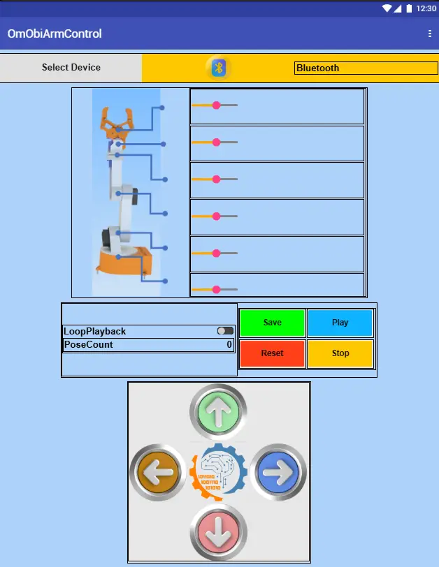
وباختصار، يوفر التطبيق الميزات التالية:
اتصال بلوتوث: First, the app connects to the HC-05 Bluetooth module on the OmObiArm. Users pair their device and establish a connection via the “Select Device” button. After connecting, the status display changes to “Connected.”
التحكم بالذراع الآلي: Six sliders in the app control the arm’s joints, from the base to the gripper. Each slider sends a position value to the corresponding servo motor in real time. So when you adjust a slider, the app sends the servo command in the format ن،زاوية\ن (على سبيل المثال، 1,90\ن لتحريك المؤازرة من 1 إلى 90 درجة).
التحكم في منصة الهاتف المحمول: Four directional buttons (Forward, Backward, Left, Right) drive the rover. A Stop button halts all motors immediately. Each button sends its single-character command followed by a newline.
إدارة الوضع: يقوم زر "حفظ" بتخزين موضع الذراع الحالي كوضعية (يرسل v\n). "تشغيل" يبدأ تشغيل الأوضاع المحفوظة (يرسل ل\ن). "إعادة تعيين" يمسح جميع التكوينات المحفوظة (يرسل ص \ ن). بالإضافة إلى ذلك، يعمل مفتاح التبديل على تمكين أو تعطيل التشغيل المتكرر (يرسل على لتمكين و و\ن للتعطيل).
عرض ردود الفعل: At the top, the app shows the current Bluetooth connection status and the number of saved poses.
إعداد اتصال بلوتوث
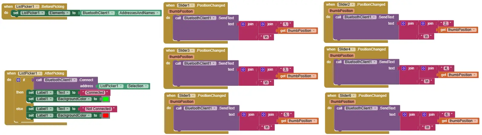
أولاً، استخدم أ ListPicker component in MIT App Inventor. In the “Before Picking” event, populate the list with available paired Bluetooth devices. In the “After Picking” event, attempt a connection to the selected device. Update the interface to display a “Connected” status. For a refresher on Bluetooth app building, see our البرنامج التعليمي لوحدة البلوتوث HC-05، والذي يغطي إعداد MIT App Inventor Bluetooth بالتفصيل.
التحكم في مفصل الذراع باستخدام المتزلجون
وبعد ذلك، أضف ستة المنزلق المكونات، واحدة لكل أجهزة. اضبط نطاق كل شريط تمرير من 0 إلى 180. في حدث "PositionChanged" لكل شريط تمرير، أرسل سلسلة الأوامر المقابلة عبر البلوتوث. على سبيل المثال، يرسل شريط التمرير 1 1,\n، يرسل المنزلق 2 2,\nوهكذا حتى Slider 6.
التحكم في حركة روفر
Add four directional زر المكونات (للأمام، للخلف، لليسار، لليمين) وزر إيقاف واحد. في حدث "TouchDown" الخاص بكل زر، أرسل سلسلة الأوامر المعنية: و\ن إلى الأمام، ب\ن للخلف، ل\ن لليسار، ص\ن للحق، و س\ن للتوقف. يمكنك أيضًا إرسال أمر الإيقاف في حدث "TouchUp" لكل زر اتجاه لتنفيذ سلوك الاستمرار في القيادة.

تشكل ضوابط الإدارة
Add buttons for Save, Play, Reset, and Stop playback, plus a toggle switch for Loop mode. Each button sends its command string: Save sends v\n، اللعب يرسل ل\ن، إعادة تعيين يرسل ص \ ن، وإيقاف الإرسال س\ن. وبالمثل، يرسل تبديل الحلقة على عند التمكين و و\ن عند تعطيله.
عرض ردود الفعل في الوقت الحقيقي
وأخيرًا، قم بإضافة مكونات التسمية لعرض حالة اتصال Bluetooth وعدد الأوضاع المحفوظة. قم بتحديث هذه التسميات ديناميكيًا أثناء اتصال المستخدم وحفظه وإعادة تعيينه.

كيف يعمل التطبيق عمليا
الاتصال بالروبوت: أولاً، افتح التطبيق وانقر على "تحديد جهاز". اختر وحدة HC-05 من قائمة أجهزة Bluetooth المقترنة. عند الاتصال، يتم تحديث تسمية الحالة إلى "متصل".
التحكم في الذراع الروبوتية: استخدم أشرطة التمرير الستة لتحريك مفاصل الذراع. يتم إرسال التعديلات إلى الروبوت في الوقت الفعلي عبر البلوتوث. يتحكم كل شريط تمرير بشكل مستقل في قناة سيرفو واحدة.
إدارة الوضعيات: To save a pose, position the arm where you want it, then tap “Save” to record the pose. You can repeat this for up to 10 poses. Tap “Play” to replay all saved poses sequentially. Optionally, enable the loop toggle for continuous playback. Tap “Stop” to halt playback at any time. Tap “Reset” to clear all saved poses.
قيادة روفر: استخدم أزرار الاتجاهات لقيادة العربة الجوالة للأمام أو للخلف أو لليسار أو لليمين. اضغط على "إيقاف" لإيقاف جميع المحركات على الفور. تذكر أن النظام يتجاهل أوامر العربة الجوالة أثناء تشغيل الوضعية من أجل السلامة.
الخطوة 7: معايرة واختبار وضبط OmObiArm
After uploading the code and installing the app, it is time to finally test and calibrate the complete OmObiArm system. Follow this sequence to verify each subsystem before attempting full operation.
7.1 فحص الاتصال
To begin with, open the OmObiArmControl app, tap “Select Device,” and pair with the HC-05 module. The HC-05 LED should change from fast blinking (pairing mode) to slow blinking or steady on (connected). The app should then display “Connected.” If the connection fails, verify that the HC-05 has power and that you have enabled Bluetooth on your phone. Note that the default pairing code is usually 1234 or 0000.
7.2 التحقق من محرك روفر
Next, test each rover movement direction one at a time. Tap Forward, Backward, Left, and Right in the app and verify the rover moves in the correct direction. If a motor spins the wrong way, swap the motor wires on the Motor Shield terminal for that motor pair. Verify that the Stop button immediately halts all movement.
7.3 معايرة المؤازرة
Test each servo channel one by one. Move Slider 1 slowly and verify that servo 1 (base rotation) responds. Repeat for all six sliders. If a servo does not respond, check the PCA9685 channel wiring and confirm the channel matches the code mapping (channels 0, 4, 8, 9, 12, 13). If a servo jitters or buzzes without moving, check the 6 V power supply from the LM2596. You can also adjust the slider range if any servo reaches its mechanical limit before the slider reaches 0 or 180. To do this, modify the PWM mapping values in the code (the الخريطة (الموقع، 0، 180، 150، 600) line) لضبط النطاق القابل للاستخدام لكل أجهزة.
7.4 التحقق من الحفظ والتشغيل
أولاً، حرك الذراع إلى موضع محدد وانقر على "حفظ". بعد ذلك، حرك الذراع إلى موضع مختلف وانقر على "حفظ" مرة أخرى. انقر الآن على "تشغيل" وتأكد من أن الذراع يعيد تشغيل الوضعين المحفوظين بسلاسة بالترتيب. اختبر "إعادة الضبط" لمسح الأوضاع، ثم تحقق من أن "تشغيل" لا يفعل شيئًا عندما لا يتم حفظ أي وضعيات. اختبر تبديل الحلقة من خلال تمكينه وبدء التشغيل. يجب أن يتنقل الذراع بين الأوضاع بشكل مستمر حتى تنقر على "إيقاف".
7.5 اختبار إجهاد العربة الجوالة والذراع المشترك
Once both subsystems work individually, test them together. Drive the rover while moving arm sliders and monitor the battery voltage under combined load. If, for example, the robot becomes sluggish, servos jitter, or the Arduino resets, you likely have power supply issues. A fully charged 7.4 V LiPo should supply enough current, but heavily loaded servos (for example, holding a heavy object with the gripper while driving) may cause voltage drops. If this happens, consider using a higher capacity battery or reducing the motor speed in the code.
7.6 تسلسل الاختبار الآمن
أخيرًا، للحصول على اختبار أول موثوق به، اتبع هذا الترتيب: (1) تشغيل الروبوت مع وضع الذراع في وضع مريح، (2) الاتصال من التطبيق، (3) اختبار حركة العربة الجوالة على سطح مستو، (4) اختبار كل شريط تمرير مؤازر ببطء، (5) اختبار الحفظ واللعب في وضعيتين بسيطتين، (6) وضع حلقة الاختبار، (7) اختبار التوقف وإعادة الضبط، (8) أخيرًا اختبار القيادة وحركة الذراع معًا. هذا النهج التدريجي يعزل المشاكل ويمنع الضرر.
استكشاف مشكلات OmObiArm الشائعة وإصلاحها
إذا لم يعمل شيء ما كما هو متوقع، فاستخدم دليل استكشاف الأخطاء وإصلاحها هذا لتحديد المشكلات الأكثر شيوعًا وإصلاحها.
أزواج HC-05 ولكن الروبوت لا يستجيب للأوامر: Verify the HC-05 TXD is connected to Arduino RX (pin 0) and RXD to Arduino TX (pin 1). Confirm the baud rate in the code is 9600, which matches the HC-05 default. To use the Serial Monitor, temporarily disconnect the HC-05 or move it to SoftwareSerial pins, then check that the code is running and printing the “Waiting for commands” message.
فشل تحميل رسم اردوينو: أولاً، افصل وحدة HC-05 عن الأطراف 0 و1 قبل التحميل. وذلك لأن HC-05 يتداخل مع اتصال USB التسلسلي المستخدم للتحميل. أعد توصيله بعد اكتمال التحميل.
مشاكل المؤازرة والمحركات
ارتعاش الماكينات أو الطنانة أو المماطلة: First, check the LM2596 output voltage. It should be exactly 6 V. If the voltage drops under load, the battery may be low or the LM2596 may not supply enough current. Check for loose PCA9685 wiring. Jitter can also result from insufficient power, especially when multiple servos move at the same time.
يتحرك العربة الجوالة لكن الذراع لا تستجيب: تحقق من صحة توصيلات PCA9685 SDA وSCL إلى Arduino Mega (الجهات 20 و21). تأكد من أن PCA9685 يستقبل 6 فولت على طرف الطاقة الخاص به. تحقق من عنوان I2C — الافتراضي هو 0x40. قم بتشغيل رسم الماسح الضوئي I2C للتأكد من أن Arduino اكتشف PCA9685.
تتحرك الذراع ولكن العربة الجوالة لا تستجيب: Check the motor wiring to the Motor Shield terminals M1 through M4. Verify that the Motor Shield sits firmly on the Arduino Mega, and check that the battery is supplying enough voltage through the Motor Shield power terminals.
تشكل وقضايا السلطة
لا يتم حفظ الأوضاع أو اللعب بشكل صحيح: First, verify you are sending the correct commands from the app (v for save, l for play). To see the pose count messages in the Serial Monitor, temporarily disconnect the HC-05 or move it to SoftwareSerial pins. Remember the maximum is 10 poses — if you have already saved 10, the system ignores additional saves.
تشغيل الحلقة لا يتوقف: First, to stop playback, send the “s” command (lowercase) from the app. During loop playback, the system checks the stop command between poses, not during servo movement. This means there may be a short delay before the loop stops. Make sure your app sends the correct character.
انخفاض الجهد والسلوك غير المنتظم تحت الحمل: في معظم الحالات، يعني هذا أن البطارية لا يمكنها توفير تيار كافٍ لتشغيل المحرك والمؤازرة في وقت واحد. ولذلك، استخدم ليبو مشحونة بالكامل. إذا استمرت المشكلة، ففكر أيضًا في استخدام بطارية ذات سعة أعلى أو تشغيل محركات العربة الجوالة ونظام المؤازرة من بطاريات منفصلة.
المحركات تدور في الاتجاه الخاطئ: Swap the two wires on the Motor Shield terminal for the affected motor. In other words, you do not need to change the code.
الأسئلة الشائعة (FAQ)
تم تصميم هذا المشروع لـ Arduino Mega 2560 لأنه يحتوي على ذاكرة أكبر، والمزيد من منافذ الإدخال/الإخراج، ومنافذ تسلسلية إضافية للأجهزة. يوصى باستخدام Mega لأن الكود المدمج وتخزين الوضع قد يتجاوز SRAM الخاص بـ Uno. إذا كان يجب عليك استخدام أونو، فقم بتقليل عدد الأوضاع المحفوظة.
يستخدم OmObiArm وحدة Bluetooth HC-05 للاتصالات اللاسلكية. في الأساس، HC-05 عبارة عن وحدة بلوتوث كلاسيكية (SPP) تعمل بسرعة 9600 باود افتراضيًا ويسهل إقرانها بأجهزة Android. للحصول على دليل كامل حول استخدام وحدتي HC-05 وHC-06، راجع البرنامج التعليمي لوحدة Bluetooth Arduino HC-05 / HC-06.
يستخدم Adafruit Motor Shield العديد من منافذ PWM الخاصة بـ Arduino، لذا يتصل PCA9685 عبر I2C بدلاً من ذلك (باستخدام SDA وSCL فقط) ويوفر 16 قناة PWM مستقلة. كما أنه يعمل على تشغيل جميع الماكينات من مصدر منفصل بجهد 6 فولت، مما يحمي Arduino.
حاليًا، يمكنك حفظ ما يصل إلى 10 أوضاع. يقوم كل وضع بتخزين قيم PWM لجميع الماكينات الستة في ذاكرة الوصول العشوائي Arduino. يتم فقدان الأوضاع عند إزالة الطاقة. يمكنك زيادة الحد الأقصى للكود أو استخدام EEPROM للتخزين المستمر.
في الأساس، يستخدم HC-05 تقنية Bluetooth Classic (SPP)، والتي لا تدعمها أجهزة iPhone محليًا. للتحكم في الروبوت من نظام iOS، استبدل HC-05 بوحدة BLE (مثل HM-10 أو ESP32 مع BLE) وقم بتحديث كود وتطبيق Arduino وفقًا لذلك.
يوصى باستخدام بطارية LiPo بقوة 7.4 فولت 2S بسعة 5300 مللي أمبير على الأقل. بشكل عام، يعمل الجهد الاسمي 7.4 فولت بشكل جيد لكل من محركات التيار المستمر (عبر Motor Shield) ومحول التنحي LM2596. توفر البطاريات ذات السعة العالية أوقات تشغيل أطول ومعالجة أفضل للتيار أثناء تشغيل العربة الجوالة والذراع معًا.
المزيد من الأسئلة الشائعة
الموارد والمشاريع القادمة
ملفات المشروع
- مستودع جيثب - أكمل كود Arduino وملف مشروع MIT App Inventor لـ OmObiArm.
- ملفات Cults3D STL | متجر أومارترونيكس - أجزاء قابلة للطباعة ثلاثية الأبعاد لهيكل OmObiArm وروابط الذراع والقابض.
دروس OmArTronics ذات الصلة
- OmObi: بناء سيارة روبوت يتم التحكم فيها عن طريق البلوتوث - مشروع قاعدة العربة الجوالة الذي يعتمد عليه OmObiArm.
- OmArm: ذراع آلي 6-DOF يمكنك صنعه بنفسك مع تحكم عبر البلوتوث - مشروع الذراع الروبوتية الذي يدمجه OmObiArm.
- الذراع الروبوتية ذات 6 أبعاد - طباعة ثلاثية الأبعاد، وتوصيل أسلاك وبرمجة - النسخة الأصلية للذراع الآلية التي يتم التحكم فيها عن طريق مقياس الجهد.
- برنامج تعليمي كامل لوحدة البلوتوث Arduino HC-05/HC-06 - دليل أساسي لفهم اتصال Bluetooth مع Arduino.
- دليل التحكم بمحرك مؤازر اردوينو: SG90، PWM، وPCA9685 - تعلم أساسيات التحكم المؤازر واستخدام برنامج التشغيل PCA9685.
- أساسيات برمجة الأردوينو: الدليل الكامل للمبتدئين - ابدأ هنا إذا كنت جديدًا في برمجة Arduino.
- سيارة روبوتية متقدمة ومستقلة مع أجهزة استشعار Arduino Mega والموجات فوق الصوتية — مشروع مماثل باستخدام نفس درع المحرك وArduino Mega بقدرات ذاتية.
- سائق محرك L298N مع اردوينو: دليل التحكم في محرك التيار المستمر - برنامج تعليمي بديل لسائق المحرك لفهم التحكم في محرك الجسر H.
الترقيات التالية المقترحة لـ OmObiArm
- تجنب العوائق بالموجات فوق الصوتية: أضف أربعة أجهزة استشعار HC-SR04 لتمكين التنقل المستقل أثناء أداء الذراع للمهام. انظر لدينا HC-SR04 البرنامج التعليمي لجهاز الاستشعار بالموجات فوق الصوتية و مشروع رادار الاردوينو للإلهام.
- تخزين وضعية EEPROM: قم بحفظ الأوضاع في EEPROM بحيث تستمر عبر دورات الطاقة، مما يسمح للروبوت بتذكر مهامه المبرمجة.
- التحكم في السرعة: أضف تحكمًا متغيرًا في السرعة للمركبة باستخدام تعديلات سرعة PWM وشرائح التطبيق بدلاً من السرعة القصوى الثابتة.
- رؤية الكاميرا والكمبيوتر: قم بتركيب وحدة كاميرا للكشف عن الأشياء المرئية وعمليات الالتقاط والمكان المستقلة.
- Wi-Fi upgrade: Replace the HC-05 with an ESP32 for Wi-Fi-based control, enabling web browser control or integration with home automation systems.
الخاتمة
لذا، إذا كنت قد اتبعت هذا البرنامج التعليمي من البداية إلى النهاية، فلديك الآن طريقة عمل ذراع روبوتية متنقلة يتم التحكم فيها عن طريق البلوتوث بنيت من الصفر. الآن، يمكن لـ OmObiArm الخاص بك القيادة في جميع الاتجاهات، وتحريك ذراع آلية ذات 6 DOF، وحفظ أوضاع الذراع وإعادة تشغيلها، وتكرار التسلسلات الآلية، وكل ذلك يتم التحكم فيه لاسلكيًا من هاتف Android الخاص بك.
During this project, you also picked up hands-on experience with 3D design and printing, mechanical assembly, electronics wiring, Arduino programming, I2C servo control with the PCA9685, DC motor control with the Adafruit Motor Shield, Bluetooth communication with the HC-05, and Android app development with MIT App Inventor. All of that carries over into more advanced robotics and automation projects.
Where to go from here: the next arm project, اوم ارم زيرو, moves from Arduino to an ESP32. You control it from the browser over Wi-Fi, and later parts add ROS 2, MoveIt 2 and a camera.
تنزيل ملفات الطباعة ثلاثية الأبعاد (STL)
جميع ملفات STL القابلة للطباعة ثلاثية الأبعاد لهذا المشروع متاحة للتنزيل. يمكنك الحصول عليها من متجرنا أو تصفحها على Cults3D:
- متجر OmArTronics: قم بتنزيل ملفات المشروع من OmArTronics — Get the print and CAD files (STL, STP) as a download. The code, wiring diagram and parts list are in this tutorial.
- الطوائف3D: عرض على Cults3D - تصفح وتنزيل ملفات النماذج ثلاثية الأبعاد على Cults3D.
مرحباً فريق أومارترونيكس بلس
آمل أن يكون كل شيء على ما يرام معك!
هذه آشلي من JLCMC، وهي علامة تجارية فرعية تابعة لشركة JLCPCB. نحن ملتزمون ببناء خدمة عالمية متكاملة. هناك أكثر من آلاف المكونات الميكانيكية التي تناسب سيناريوهات الاستخدام والاحتياجات المختلفة.
لقد أُعجبنا بنهجك العملي ومشاريعك الإبداعية التي تقوم بها بنفسك، خاصةً عملك مع الأذرع الروبوتية. إن تركيزكم على الحلول العملية والمبتكرة يتوافق تمامًا مع مهمتنا في شركة JLCMC لتوفير مكونات ميكانيكية عالية الجودة. نحن نعتقد أن التعاون سيكون مفيدًا للطرفين، حيث إن اهتمام جمهورك بالروبوتات والأتمتة يتطابق بشكل وثيق مع الحلول التي نقدمها. ستسمح لنا الشراكة معكم بتقديم قطعنا الدقيقة إلى مجتمع مهتم بالتكنولوجيا ومتحمس للتقنيات الذكية والفعالة.
سنكون سعداء بتزويدك بمنتجاتنا لاستخدامك، إذا كنت مهتمًا أو إذا كنت بحاجة إلى تحديث مكوناتك أو لديك أي أسئلة أخرى، فلا تتردد في الاتصال بنا!
أشكرك على وقتك وأتطلع إلى الاستماع منك!
مع أطيب التحيات
آشلي