

📋 Quick Summary
Build OmObiArm — a Bluetooth-controlled mobile robot with an integrated 4-DOF robotic arm powered by Arduino Mega, HC-05, Adafruit Motor Shield, and PCA9685 servo driver. This tutorial covers the complete build process: 3D-printed chassis and arm design, dual motor driving, servo arm control, and smartphone Bluetooth control via MIT App Inventor.
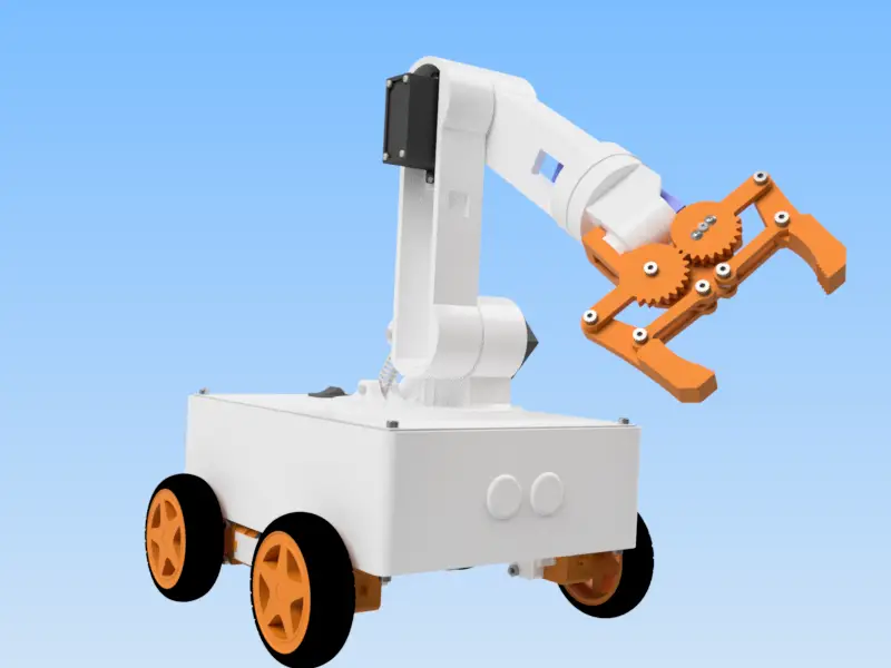
Want to build a mobile robot that can drive around and pick things up? So in this tutorial, you will build OmObiArm, a Bluetooth-controlled mobile robot arm powered by Arduino. Since OmObiArm pairs a four-wheel rover base with a 6-DOF robotic arm, all controlled wirelessly from a custom Android app through an HC-05 Bluetooth module. During this project, you will also learn how to design the chassis, assemble the mechanics, wire the Adafruit Motor Shield and PCA9685 servo driver, program the Arduino, and build a control app using MIT App Inventor. Finally, by the end, you will have a working DIY mobile robot arm that can drive, reach, grab, and replay saved arm poses on its own.
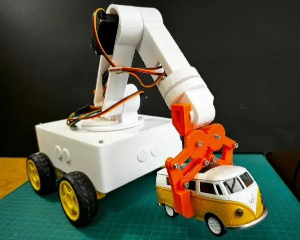
Basically, OmObiArm is an upgraded project that combines two of our previous builds: OmObi, the Bluetooth-controlled mobile robot, and OmArm, the 6-DOF robotic arm with Bluetooth control. Once it is mounted on its mobile platform, OmObiArm can drive in all directions while you independently control six arm joints through sliders in the app. In addition, a “Save” button records arm positions, and a “Play” button replays them as automated sequences. So if you want to learn mechatronics, automation logic, or wireless Bluetooth robot control, this is a solid project to try.
What You Will Learn
- How the OmObiArm combines rover mobility with robotic arm manipulation in a single Arduino-controlled platform.
- How the Adafruit Motor Shield V1.2 drives four DC motors for omnidirectional movement of the mobile base.
- How the PCA9685 servo driver controls six servos (three MG996R and three SG90) for precise arm and gripper control.
- How the HC-05 Bluetooth module enables wireless communication between your Android phone and the Arduino.
- How to save, play, loop, and reset arm poses for automated task sequences.
- How to build the Android control app using MIT App Inventor with sliders, buttons, and Bluetooth logic.
- How to test, calibrate, and troubleshoot the complete system including power, servos, motors, and Bluetooth connectivity.
How OmObiArm Works
Before you start building, it helps to understand how everything fits together. In short, OmObiArm uses an Arduino Mega 2560 as its central controller. Then, the Arduino receives Bluetooth commands from your phone through the HC-05 module connected on the hardware serial pins (TX/RX on pins 0 and 1). Then, based on the received command string, it either drives the rover or moves the robotic arm.
For rover movement, the Arduino then sends commands to the Adafruit Motor Shield V1.2, which controls four DC motors through its built-in L293D dual H-bridge drivers. In fact, the motor shield sits directly on top of the Arduino Mega. If you want more details on how motor shields work, see our Bluetooth-controlled robot car with Adafruit Motor Shield tutorial.
Arm Control and Wireless Communication
Meanwhile, for arm control, the Arduino communicates with the PCA9685 16-channel servo driver over I2C. Then, the PCA9685 generates PWM signals for six servos spread across channels 0, 4, 8, 9, 12, and 13. Of these, three MG996R servos handle the heavy base and shoulder joints, while three SG90 micro servos handle the lighter wrist and gripper joints. Also, the PCA9685 gets its power independently through an LM2596 buck converter that steps down the main 7.4 V LiPo battery to 6 V. Because of this, it keeps the Arduino’s onboard regulator from being overloaded. To learn more about servo control with the PCA9685, see our Arduino servo motor control guide.
At the same time, the Android control app (built with MIT App Inventor) sends single-character commands for rover movement (F, B, L, R, S) and formatted servo commands (for example, “1,90” to move servo 1 to 90 degrees) over Bluetooth. The app also sends pose management commands: “v” to save, “l” to play, “r” to reset, “s” to stop, “o” to enable loop, and “f” to disable loop. Also, while poses are playing back, the rover motors stop automatically so the robot does not drive off unexpectedly. To learn more about the HC-05 module, visit our HC-05 / HC-06 Bluetooth module complete tutorial.
Components Needed for the OmObiArm Mobile Robot Arm
Overall, to build the OmObiArm, you will need 3D-printed parts from both the OmObi rover and the OmArm robotic arm, plus the following electronics, motors, and hardware. Below, the full bill of materials (BOM) table below lists every required part along with its quantity and purpose.
Summary of Key Components
| Category | Components |
|---|---|
| Controller | Arduino Mega 2560 |
| Motor Driver | Adafruit Motor Shield V1.2 (L293D-based) |
| Servo Driver | PCA9685 16-channel I2C servo driver |
| Bluetooth | HC-05 Bluetooth module |
| Motors | 4 DC motors with gearboxes + 4 wheels |
| Servos | 3 MG996R (high torque) + 3 SG90 (micro) |
| Power | 7.4 V 2S LiPo battery (5300 mAh) + LM2596 buck converter (stepped to 6 V) + power switch |
| 3D-Printed Parts | Chassis, arm links, gripper, base, covers, Arduino holder (from OmObi and OmArm designs) |
| Accessories | Jumper wires, M3 screws, inserts, M2 screws, extension spring, joint pin, ball bearing (6806ZZ 30x42x7), servo horns |
Complete Bill of Materials (BOM)
Basically, the following table is the complete bill of materials for the OmObiArm project. It also covers all 3D-printed structural parts, servos, electronics, fasteners, and accessories. Also, you can download items marked as “3D printed” as STL files from Cults3D or get them from our OmArTronics Shop.
Full parts list
| Item | Qty | Part | Purpose / Notes |
|---|---|---|---|
| 1 | 1 | Lower Base (Chassis) | 3D printed lower base for mounting motors and electronics |
| 2 | 1 | JIS B 1521 – 6806 30x42x7 | Deep groove ball bearing for arm base rotation |
| 3 | 1 | Arm Link 1 | 3D printed first arm link |
| 4 | 1 | Gripper Finger Right | Right finger of the gripper, 3D printed |
| 5 | 2 | Gripper Sleeve | Plastic sleeve for gripper joint axis |
| 6 | 1 | Gripper Gear Right | Right-side gear for gripper mechanism |
| 7 | 1 | Gripper Gear Left | Left-side gear for gripper mechanism |
| 8 | 1 | Gripper Assembly | 3D printed complete gripper assembly |
| 9 | 4 | Link | Generic linkage parts, 3D printed |
| 10 | 1 | Arm Base Upper | 3D printed upper base part of the robotic arm |
| 11 | 3 | SG90 Micro Servo | Compact servo for gripper and lightweight joints |
| 12 | 3 | MG996R Servo | High-torque servo for base and heavy-load joints |
| 13 | 1 | Arm Link 3 | 3D printed third arm link |
| 14 | 1 | Arm Link 2 | 3D printed second arm link |
| 15 | 1 | Arm Base Link | 3D printed base for connecting the robotic arm to the rover |
| 16 | 7 | AS 1420 – 1973 – M3 x 16 | Hex socket head cap screw |
| 17 | 1 | Extension Spring | Spring for linkage tension |
| 18 | 1 | Joint Pin | Pin used to fix joints in the robotic arm |
| 19 | 1 | ANSI B18.2.4.2M – M3x0.5 | Hex nut (standard metric thread) |
| 20 | 3 | MG955 Horn | Servo horns for MG996R servos |
| 21 | 3 | SG90 Servo Horn | Horns for SG90 servos |
| 22 | 8 | ANSI B18.6.4 – No. 3 – 28 – 1/2 | Cross recessed truss head tapping screw – Type AB – Type I |
| 23 | 16 | ANSI B18.6.4 – No. 2 – 32 – 3/8 | Cross recessed truss head tapping screw – Type AB – Type I |
Fasteners, electronics, and chassis parts
| Item | Qty | Part | Purpose / Notes |
|---|---|---|---|
| 24 | 2 | DIN 7985 (Z) – M3x6-Z | Cross recessed raised cheese head screws – Type Z |
| 25 | 3 | DIN 7985 (Z) – M2x6-Z | Cross recessed raised cheese head screws – Type Z |
| 26 | 4 | Motor Gear | Plastic gear for DC motor shaft |
| 27 | 4 | 4WD Tyre | Rubber wheel for mobile base |
| 28 | 4 | 4WD Buggy Wheel | Plastic wheel for 4WD platform |
| 29 | 1 | Chassis Frame | 3D printed chassis frame for structural support |
| 30 | 3 | Cover | 3D printed covers |
| 31 | 1 | Robot Car Base | 3D printed base |
| 32 | 1 | Arduino Mega 2560 | Microcontroller for control and Bluetooth communication |
| 33 | 1 | L293D Motor Driver (Adafruit Motor Shield V1.2) | Dual H-bridge motor shield for DC motor control |
| 34 | 1 | 7.4 V 2S LiPo Battery (5300 mAh) | Main power supply for the entire system |
| 35 | 16 | M3 Inserts | Threaded heat-set inserts for 3D printed parts |
| 36 | 1 | Switch | Power on/off switch for main circuit |
| 37 | 16 | AS 1420 – 1973 – M3 x 6 | ISO metric hexagon socket head cap screws |
| 38 | 4 | ANSI B18.3.1M – M3x0.5 x 30 | Broached socket head cap screw – Metric |
| 39 | 4 | ANSI B18.3.1M – M3x0.5 x 25 | Broached socket head cap screw – Metric |
| 40 | 1 | HC-05 Bluetooth Module | Wireless communication module for Bluetooth control |
| 41 | 4 | ANSI B18.6.4 – No. 0 – 48 – 1/4 | Cross recessed truss head tapping screw – Type AB – Type I |
| 42 | 1 | LM2596 Buck Converter | DC-DC step-down converter to supply 6 V to PCA9685 |
| 43 | 1 | PCA9685 Servo Driver | I2C-based 16-channel servo driver board |
| 44 | 4 | DC Motor with Gearbox | Geared DC motors for the 4WD rover base |
Step 1: OmObiArm 3D Model Design for the Mobile Robot Arm
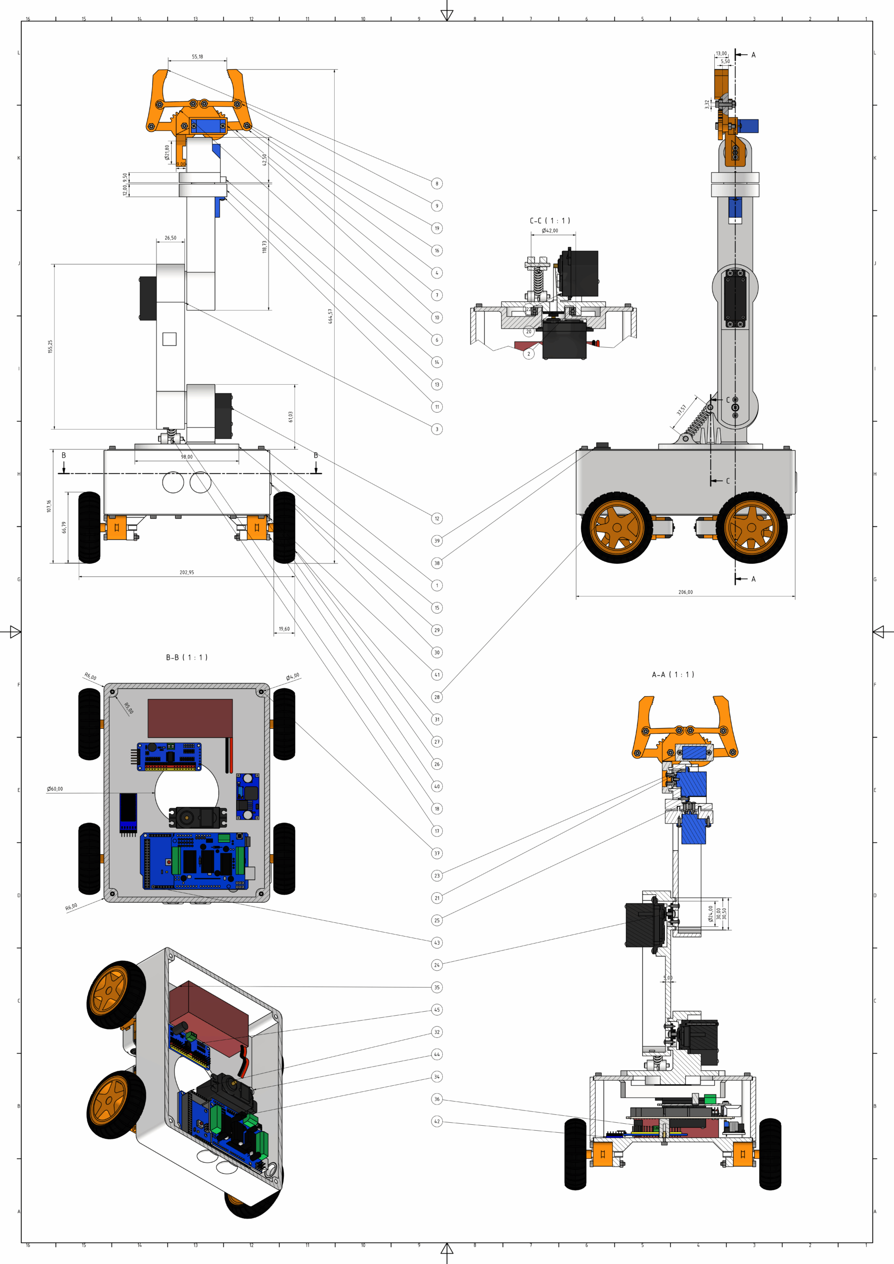
First of all, this step combines designs from the previous OmObi rover and OmArm robotic arm projects. Then, using Autodesk Inventor, we modified the OmArm base and merged it with the top plate (lid) design from the OmObi. As a result, the platform that securely mounts the robotic arm onto the mobile chassis. If you are new to 3D design for robotics, see our introduction to 3D printing and Autodesk Inventor guide.
Also, you can download the STL files for 3D printing from Cults3D or from our OmArTronics Shop. To help with assembly, we designed all components with detailed dimensions, which you can see in the technical drawing below. In addition, the drawing includes sectional views so you can get a clear picture of the mechanical design and assembly layout.
Step 2: 3D Printing the Robotic Parts
After finalizing the design, 3D print all the components. For example, using a 3D printer like the Creality Ender 3, print all the parts listed in the BOM for both the robotic arm and the mobile platform. Generally, PLA filament works well for most parts. We also designed these parts to be easy to assemble and sturdy enough for regular use. Also, for tips on printer settings and material selection, see our introduction to 3D printing tutorial.
Step 3: Assembling the OmObiArm Robot
Once all the 3D-printed parts are ready, it is time to assemble the OmObiArm mobile robot arm. Because of this, follow each sub-step carefully and verify fit and alignment before tightening screws.
3.1 Mounting the Motors and Wheels
Attach the Motors: Secure the four DC motors to the 3D-printed motor mounts using screws, inserts, and nuts. Also make sure they are firmly attached to prevent any misalignment during movement.
Mount the Wheels: Attach the wheels to the motor shafts and ensure they are tightly fixed. Then test for smooth rotation and proper alignment.
3.2 Mounting the Arduino Mega, Motor Shield, PCA9685, LM2596, and HC-05
Attach the Arduino Holder: First, secure the 3D-printed Arduino holder to the mobile chassis using screws.
Mount the Arduino and Motor Shield: Place the Arduino Mega in the holder and secure it with screws. Then attach the Adafruit Motor Shield on top of the Arduino Mega, making sure all pins are correctly aligned and seated.
Then, fix the PCA9685, LM2596, and HC-05: Use zip ties or double-sided tape to fix the PCA9685 servo driver, LM2596 step-down converter, and the HC-05 Bluetooth module onto the chassis. Also, position them so that wiring runs are short and tidy.
3.3 Fixing the Top Plate and Robotic Arm Base
Finally, attach the top plate (which is also the robotic arm base) onto the moving platform. Then use screws to secure it firmly. As a result, this gives the robotic arm a stable mounting surface and prevents wobble during movement.
3.4 Assembling the Robotic Arm
Now, the robotic arm assembly follows the same procedure described in our OmArm build guide. Therefore, follow these sub-steps carefully, since each one builds on the previous:
Sub-step 1 — Securing the Servo Motor on the Base: Install the first MG996R servo motor onto the robotic arm’s base using M3x12 screws. Then, add the 6806ZZ ball bearing (30x42x7 mm) to reduce friction and enable smooth rotation. Then attach the servo horn to the rotating upper part and secure it with M2x12 screws. Also, ensure the connection is tight and aligned.
Sub-step 2 — Mounting Servo Horns to Robot Arm Links: Align the servo horns with the arm links’ attachment points. Then secure them with screws, tightening them firmly to prevent slippage.
Sub-step 3 — Mounting Servo Motors to Arm Links: Align the servo motors with the mounting points on the arm links. Then secure them using screws, and make sure the fit is tight and stable. After that, test the stability by gently moving the links.
Sub-step 4 — Connecting the Arm Links: Align the links and connect them using screws through the servo horns. Also double-check that the joints move smoothly and are securely fastened.
Sub-step 5 — Assembling the Gripper: Finally, attach the gripper to the end link of the robotic arm using M3x20 screws. After that, verify that the gripper opens and closes smoothly and sits properly on the arm.
3.5 Final Assembly Checks
Once the robotic arm and mobile platform are fully assembled, test all components for stability and smooth operation. Before moving on, make sure the motors, servos, and gripper all work correctly before moving on to wiring and programming.
Step 4: Wiring the OmObiArm Components
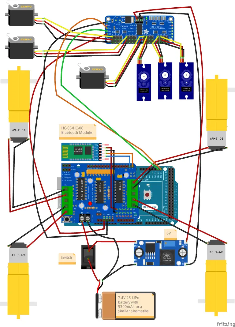
Getting the wiring right matters a lot for this project because bad connections can damage components or cause unpredictable behavior. The following sub-sections walk you through each connection group. Also, refer to the wiring diagram below for the complete circuit layout.
4.1 DC Motors to Motor Shield
| Motor | Motor Shield Terminal | Side |
|---|---|---|
| Left Front Motor | M1 | Left |
| Left Rear Motor | M2 | Left |
| Right Front Motor | M3 | Right |
| Right Rear Motor | M4 | Right |
First, attach the left-side motors to the terminals labeled M1 and M2 on the Adafruit Motor Shield, and the right-side motors to M3 and M4. After that, check the polarity so that all wheels spin in the right direction when a forward command is sent.
4.2 Battery and Main Power Path
Use a 7.4 V 2S LiPo battery with at least 5300 mAh capacity and an EC3 connector. Then, solder a compatible EC3 plug to the input of the circuit. Also, add a power switch between the battery and the circuit to easily control power flow. Overall, the battery supplies power to both the Adafruit Motor Shield (which powers the Arduino through its onboard regulator) and, in parallel, to the LM2596 buck converter.
4.3 LM2596 DC-DC Step-Down Converter
| LM2596 Pin | Connection |
|---|---|
| IN+ | Battery positive (7.4 V, via switch) |
| IN− | Battery ground |
| OUT+ | PCA9685 VCC terminal (adjusted to 6 V) |
| OUT− | PCA9685 GND terminal |
First, connect the battery in parallel to the LM2596 step-down converter. Before connecting the PCA9685, adjust the potentiometer on the LM2596 to set the output voltage to exactly 6 V using a multimeter. Because of this, the independent 6 V supply powers the PCA9685 servo driver board and all connected servos, avoiding overload on the Arduino’s onboard regulator.
4.4 PCA9685 Servo Driver and Servos
| PCA9685 Pin | Connection |
|---|---|
| VCC (power terminal) | LM2596 output 6 V |
| GND (power terminal) | LM2596 output GND |
| SDA | Arduino Mega SDA (pin 20) |
| SCL | Arduino Mega SCL (pin 21) |
| VCC (logic) | Arduino 5 V |
| GND (logic) | Arduino GND |
Next, connect each servo to the appropriate PCA9685 channel, making sure the signal, VCC, and GND pins are aligned correctly. Also, the servo channel assignments used in the code are:
| Servo | Joint | PCA9685 Channel | Type |
|---|---|---|---|
| Servo 1 | Base rotation | 0 | MG996R |
| Servo 2 | Shoulder | 4 | MG996R |
| Servo 3 | Elbow | 8 | MG996R |
| Servo 4 | Wrist pitch | 9 | SG90 |
| Servo 5 | Wrist roll | 12 | SG90 |
| Servo 6 | Gripper | 13 | SG90 |
Also, make sure you use the independent 6 V power source from the LM2596 for the PCA9685 servo power terminal. In other words, do not power the servos from the Arduino’s 5 V pin — this will cause voltage drops, servo jitter, and possible Arduino resets.
4.5 HC-05 Bluetooth Module
| HC-05 Pin | Arduino Mega Pin |
|---|---|
| VCC | 5 V |
| GND | GND |
| TXD | RX0 (Pin 0) |
| RXD | TX0 (Pin 1) |
Important note about Pins 0 and 1: The HC-05 connects to the Arduino Mega’s hardware serial pins (Serial0, pins 0 and 1). Since these are the same pins used by the USB connection for uploading sketches, you must disconnect the HC-05 (or at least disconnect the HC-05 TXD wire from pin 0) before uploading code from the Arduino IDE. If you leave the HC-05 connected during upload, the upload will fail with a communication error. After that, reconnect the HC-05. Also, for a detailed guide on HC-05 wiring and pairing, see our Arduino HC-05 / HC-06 Bluetooth module tutorial.
4.6 Adafruit Motor Shield to Arduino Mega
Then, place the Adafruit Motor Shield securely onto the Arduino Mega, making sure all pins align and seat correctly. Instead, the Motor Shield piggybacks directly on top of the Arduino headers, so no additional wiring is needed between the shield and the Arduino — the shield communicates through the stacked pin headers. For more on how the Adafruit Motor Shield works, see our Bluetooth robot car with Adafruit Motor Shield tutorial.
4.7 Testing the Power Distribution
Before powering on the system for the first time, check all power connections with a multimeter. Also, look for short circuits. Then, make sure the motors, servos, and HC-05 module are each getting the right voltage: the Arduino and HC-05 should see 5 V, the servos should see 6 V from the LM2596, and the motors should get the full battery voltage through the Motor Shield.
Step 5: Programming the Mobile Robot Arm OmObiArm for Bluetooth Control
In this step, we program the Arduino Mega to control the robotic arm and the mobile platform over Bluetooth. Overall, the complete code handles Bluetooth command parsing, rover motor control, smooth servo movement, and pose save/play/loop logic. Also, you can find the complete source code and the MIT App Inventor project file in the GitHub Repository: App and Code. If you are new to Arduino programming, we recommend reviewing our Arduino programming basics tutorial first.
Important: Always remember to disconnect the HC-05 module from pins 0/1 before uploading this sketch. Afterward, reconnect it after the upload completes.
Complete OmObiArm Arduino Code
#include <Wire.h>
#include <Adafruit_PWMServoDriver.h>
#include <AFMotor.h>

// Constants and definitions
const int numServos = 6; // Number of servos
const int maxConfigurations = 10; // Maximum number of storable poses
const int stepDelay = 10; // Delay between each step to slow down the servo movement
const int stepSize = 1;   // The number of degrees to move per step

// Servo channels on the PCA9685
const int servoChannels[numServos] = {0, 4, 8, 9, 12, 13};

// Storage structures
int savedConfigurations[maxConfigurations][numServos];
int currentServoPositions[numServos] = {375, 375, 375, 375, 375, 375}; // Default positions
int configCount = 0;            // Counter for stored poses
bool isPlaying = false;         // Status indicating if poses are being played
bool loopPlayback = false;      // Status indicating if poses should be played in a loop
bool stopPlaying = false;       // Status indicating if playback should be stopped
int currentPoseIndex = 0;       // Index of the current pose during playback

// Motor instances for the rover
AF_DCMotor motor1(1);
AF_DCMotor motor2(2);
AF_DCMotor motor3(3);
AF_DCMotor motor4(4);

Adafruit_PWMServoDriver pwm = Adafruit_PWMServoDriver();
String input = ""; // Holds incoming Bluetooth data

void setup() {
  Serial.begin(9600); // Serial communication for Bluetooth

  // Initialize motors
  motor1.setSpeed(255);
  motor2.setSpeed(255);
  motor3.setSpeed(255);
  motor4.setSpeed(255);

  // Initialize servo controller
  pwm.begin();
  pwm.setPWMFreq(50); // Set frequency to 50 Hz for servos

  // Initialize servo positions
  for (int i = 0; i < numServos; i++) {
    pwm.setPWM(servoChannels[i], 0, currentServoPositions[i]);
  }

  Serial.println("Bluetooth Robot Controller ready. Waiting for commands...");
}
Main Loop and Command Processing Code
void loop() {
  // Process incoming commands
  if (Serial.available()) {
    input = Serial.readStringUntil('\n'); // Read data from Bluetooth
    input.trim();

    Serial.println("Received command: " + input);
    processCommand(input);
  }

  // Check if robot arm is playing poses
  if (isPlaying && !stopPlaying) {
    if (loopPlayback) {
      playPosesInLoop();
    } else {
      playNextPose();
    }
  }
}
Command processing code
void processCommand(String command) {
  // If playing, ignore all rover commands
  if (isPlaying) {
    if (command == "s") { // Allow stop playback command
      stopPlayingPoses();
    } else {
      Serial.println("Playback in progress. Ignoring command: " + command);
    }
    return;
  }

  // Control rover movement
  if (command == "F") {
    forward();
  } else if (command == "B") {
    backward();
  } else if (command == "L") {
    turnLeft();
  } else if (command == "R") {
    turnRight();
  } else if (command == "S") {
    stopMotors(); // Stop motors immediately on "S" command

  // Control robotic arm
  } else if (command.startsWith("1,")) {
    processServoCommand(command, 0); // Control Servo 1
  } else if (command.startsWith("2,")) {
    processServoCommand(command, 1); // Control Servo 2
  } else if (command.startsWith("3,")) {
    processServoCommand(command, 2); // Control Servo 3
  } else if (command.startsWith("4,")) {
    processServoCommand(command, 3); // Control Servo 4
  } else if (command.startsWith("5,")) {
    processServoCommand(command, 4); // Control Servo 5
  } else if (command.startsWith("6,")) {
    processServoCommand(command, 5); // Control Servo 6

  // Save, play, reset poses
  } else if (command == "v") {
    saveCurrentPose();
  } else if (command == "l") {
    startPlayingPoses();
  } else if (command == "r") {
    resetPoses();
  } else if (command == "s") {
    stopPlayingPoses();
  } else if (command == "o") {
    loopPlayback = true;
    Serial.println("Loop playback enabled.");
  } else if (command == "f") {
    loopPlayback = false;
    Serial.println("Loop playback disabled.");
  } else {
    Serial.println("Unknown command: " + command);
  }
}

void processServoCommand(String command, int servoIndex) {
  int commaIndex = command.indexOf(',');
  if (commaIndex > 0) {
    int position = command.substring(commaIndex + 1).toInt();
    int pwmValue = map(position, 0, 180, 150, 600);
    moveToPositionSmoothly(servoIndex, pwmValue);
  }
}

// Rover motor control
Rover movement and pose playback code
Motor Control and Pose Functions
void forward() {
  motor1.run(FORWARD);
  motor2.run(FORWARD);
  motor3.run(FORWARD);
  motor4.run(FORWARD);
  Serial.println("Moving forward");
}

void backward() {
  motor1.run(BACKWARD);
  motor2.run(BACKWARD);
  motor3.run(BACKWARD);
  motor4.run(BACKWARD);
  Serial.println("Moving backward");
}

void turnLeft() {
  motor1.run(BACKWARD);
  motor2.run(BACKWARD);
  motor3.run(FORWARD);
  motor4.run(FORWARD);
  Serial.println("Turning left");
}

void turnRight() {
  motor1.run(FORWARD);
  motor2.run(FORWARD);
  motor3.run(BACKWARD);
  motor4.run(BACKWARD);
  Serial.println("Turning right");
}

void stopMotors() {
  motor1.run(RELEASE);
  motor2.run(RELEASE);
  motor3.run(RELEASE);
  motor4.run(RELEASE);
  Serial.println("Motors stopped");
}

// Arm servo control
void moveToPositionSmoothly(int servoIndex, int targetPwmValue) {
  int currentPwmValue = currentServoPositions[servoIndex];
  if (targetPwmValue > currentPwmValue) {
    for (int pos = currentPwmValue; pos <= targetPwmValue; pos += stepSize) {
      pwm.setPWM(servoChannels[servoIndex], 0, pos);
      delay(stepDelay);
    }
  } else {
    for (int pos = currentPwmValue; pos >= targetPwmValue; pos -= stepSize) {
      pwm.setPWM(servoChannels[servoIndex], 0, pos);
      delay(stepDelay);
    }
  }
  currentServoPositions[servoIndex] = targetPwmValue;
  Serial.println("Servo " + String(servoIndex + 1) + " set to position: " + String(targetPwmValue));
}

// Pose handling for the arm
Pose Management Functions
void saveCurrentPose() {
  if (configCount < maxConfigurations) {
    for (int i = 0; i < numServos; i++) {
      savedConfigurations[configCount][i] = currentServoPositions[i];
    }
    configCount++;
    Serial.println("Pose saved. Total poses: " + String(configCount));
  } else {
    Serial.println("Memory full. Cannot save pose.");
  }
}

void startPlayingPoses() {
  if (configCount > 0) {
    stopMotors(); // Ensure rover is stopped during playback
    isPlaying = true;
    stopPlaying = false;
    currentPoseIndex = 0;
    Serial.println("Starting pose playback");
  } else {
    Serial.println("No poses saved");
  }
}

void playNextPose() {
  if (currentPoseIndex < configCount) {
    for (int i = 0; i < numServos; i++) {
      moveToPositionSmoothly(i, savedConfigurations[currentPoseIndex][i]);
    }
    delay(1000);
    currentPoseIndex++;
  } else {
    isPlaying = false;
    Serial.println("Pose playback finished");
  }
}

void playPosesInLoop() {
  for (int i = 0; i < configCount; i++) {
    if (stopPlaying) break; // Immediate stop on command
    for (int j = 0; j < numServos; j++) {
      moveToPositionSmoothly(j, savedConfigurations[i][j]);
    }
    delay(1000);
  }
}

void stopPlayingPoses() {
  stopPlaying = true;
  isPlaying = false;
  Serial.println("Pose playback stopped");
}

void resetPoses() {
  configCount = 0;
  isPlaying = false;
  loopPlayback = false;
  currentPoseIndex = 0;
  Serial.println("All poses reset");
}
Code Walkthrough: Included Libraries
#include <Wire.h>
#include <Adafruit_PWMServoDriver.h>
#include <AFMotor.h>
First, you need three libraries for this project. Wire.h provides I2C communication, which the PCA9685 servo driver uses to receive commands from the Arduino. Adafruit_PWMServoDriver.h is the library for controlling servos through the PCA9685 board. And AFMotor.h is the Adafruit Motor Shield library that simplifies DC motor control through the L293D H-bridges on the shield. Before compiling, make sure all three are installed in your Arduino IDE before compiling.
Code Walkthrough: Servo Channel Mapping and Variables
const int numServos = 6;
const int maxConfigurations = 10;
const int stepDelay = 10;
const int stepSize = 1;
const int servoChannels[numServos] = {0, 4, 8, 9, 12, 13};
int savedConfigurations[maxConfigurations][numServos];
int currentServoPositions[numServos] = {375, 375, 375, 375, 375, 375};
int configCount = 0;
bool isPlaying = false;
bool loopPlayback = false;
bool stopPlaying = false;
int currentPoseIndex = 0;
Next, the constants define the system parameters. numServos is set to 6 because the arm has six joints. maxConfigurations limits the number of saved poses to 10 (stored in RAM). stepDelay (10 ms) and stepSize (1 PWM unit) control how smoothly the servos move. Smaller step sizes with short delays produce fluid motion instead of abrupt jumps. The servoChannels array maps each logical servo (1 through 6) to its physical PCA9685 channel (0, 4, 8, 9, 12, 13). The currentServoPositions array tracks where each servo currently is, using raw PWM values (375 is roughly mid-range for a 150 to 600 PWM mapping). Finally, the boolean flags isPlaying, loopPlayback, and stopPlaying manage the state machine for pose playback.
Code Walkthrough: Motor Initialization
AF_DCMotor motor1(1);
AF_DCMotor motor2(2);
AF_DCMotor motor3(3);
AF_DCMotor motor4(4);
Adafruit_PWMServoDriver pwm = Adafruit_PWMServoDriver();
Next, four DC motor objects are created on channels 1 through 4 of the Adafruit Motor Shield. The Adafruit_PWMServoDriver object (named pwm) is initialized with the default I2C address (0x40) of the PCA9685 board. However, if you have multiple PCA9685 boards, you would pass a different address here.
Code Walkthrough: Setup Function
void setup() {
  Serial.begin(9600);
  motor1.setSpeed(255);
  motor2.setSpeed(255);
  motor3.setSpeed(255);
  motor4.setSpeed(255);
  pwm.begin();
  pwm.setPWMFreq(50);
  for (int i = 0; i < numServos; i++) {
    pwm.setPWM(servoChannels[i], 0, currentServoPositions[i]);
  }
}
During startup, the setup function initializes serial communication at 9600 baud, which must match the HC-05’s default baud rate. After that, it sets all four motors to maximum speed (255 out of 255), initializes the PCA9685 at a PWM frequency of 50 Hz (the standard for hobby servos), and moves all six servos to their default mid-range positions (PWM value 375) so the arm starts in a known, safe pose.
Code Walkthrough: Bluetooth Command Format and the Loop Function
void loop() {
  if (Serial.available()) {
    input = Serial.readStringUntil('\n');
    input.trim();
    processCommand(input);
  }
  if (isPlaying && !stopPlaying) {
    if (loopPlayback) {
      playPosesInLoop();
    } else {
      playNextPose();
    }
  }
}
Now, the main loop continuously checks for incoming Bluetooth data on the serial port. When data is available, it reads a complete command string up to the newline character ('\n') using readStringUntil('\n'). So the newline acts as the command delimiter, so each command sent from the app ends with \n. After trimming whitespace, the command string goes to processCommand(). Meanwhile, the second half of the loop checks if pose playback is active, and if so, it either plays poses in a loop or advances to the next pose in sequence.
Code Walkthrough: Command Processing (Rover and Arm)
void processCommand(String command) {
  if (isPlaying) {
    if (command == "s") { stopPlayingPoses(); }
    return;
  }
  if (command == "F") forward();
  else if (command == "B") backward();
  else if (command == "L") turnLeft();
  else if (command == "R") turnRight();
  else if (command == "S") stopMotors();
  else if (command.startsWith("1,")) processServoCommand(command, 0);
  else if (command.startsWith("2,")) processServoCommand(command, 1);
  else if (command.startsWith("3,")) processServoCommand(command, 2);
  else if (command.startsWith("4,")) processServoCommand(command, 3);
  else if (command.startsWith("5,")) processServoCommand(command, 4);
  else if (command.startsWith("6,")) processServoCommand(command, 5);
  else if (command == "v") saveCurrentPose();
  else if (command == "l") startPlayingPoses();
  else if (command == "r") resetPoses();
  else if (command == "s") stopPlayingPoses();
  else if (command == "o") { loopPlayback = true; }
  else if (command == "f") { loopPlayback = false; }
}
The processCommand() function is the central command dispatcher. It first checks whether pose playback is active. If it is, only the “s” (stop) command is accepted and all other commands are ignored. As a result, this prevents rover movement during arm playback, which could cause the robot to drive off unexpectedly.
In summary, the complete command protocol is as follows:
Rover and Arm Command Reference
| Command | Action | Category |
|---|---|---|
F | Drive rover forward | Rover |
B | Drive rover backward | Rover |
L | Turn rover left | Rover |
R | Turn rover right | Rover |
S | Stop all rover motors | Rover |
1,<angle> | Move servo 1 (base) to angle (0–180) | Arm |
2,<angle> | Move servo 2 (shoulder) to angle | Arm |
3,<angle> | Move servo 3 (elbow) to angle | Arm |
4,<angle> | Move servo 4 (wrist pitch) to angle | Arm |
5,<angle> | Move servo 5 (wrist roll) to angle | Arm |
6,<angle> | Move servo 6 (gripper) to angle | Arm |
v | Save current arm pose | Pose |
l | Start playing saved poses | Pose |
r | Reset (clear) all saved poses | Pose |
s | Stop pose playback | Pose |
o | Enable loop playback mode | Pose |
f | Disable loop playback mode | Pose |
Servo Command Format and Processing
When controlling the arm, servo commands use the format "N,angle", where N is the servo number (1–6) and angle is the position in degrees (0–180). The processServoCommand() function parses this string, extracts the angle value, maps it from the 0–180 degree range to the PCA9685 PWM range (150–600), and calls the smooth movement function.
Code Walkthrough: Rover Motor Control Functions
void forward() {
  motor1.run(FORWARD); motor2.run(FORWARD);
  motor3.run(FORWARD); motor4.run(FORWARD);
}
void backward() {
  motor1.run(BACKWARD); motor2.run(BACKWARD);
  motor3.run(BACKWARD); motor4.run(BACKWARD);
}
void turnLeft() {
  motor1.run(BACKWARD); motor2.run(BACKWARD);
  motor3.run(FORWARD); motor4.run(FORWARD);
}
void turnRight() {
  motor1.run(FORWARD); motor2.run(FORWARD);
  motor3.run(BACKWARD); motor4.run(BACKWARD);
}
void stopMotors() {
  motor1.run(RELEASE); motor2.run(RELEASE);
  motor3.run(RELEASE); motor4.run(RELEASE);
}
Next, each movement function controls all four motors simultaneously through the Adafruit Motor Shield. For forward and backward movement, all four motors spin in the same direction. For turning, the motors on one side run forward while the other side runs backward (skid-steer / tank-turn style). The stopMotors() function uses RELEASE to cut power to all motors. Also, the motor speed is set to 255 (maximum) in setup; you can lower this value if you want slower, more controlled movement. For a deeper look at DC motor control, see our L298N motor driver tutorial.
Code Walkthrough: Smooth Servo Movement
void moveToPositionSmoothly(int servoIndex, int targetPwmValue) {
  int currentPwmValue = currentServoPositions[servoIndex];
  if (targetPwmValue > currentPwmValue) {
    for (int pos = currentPwmValue; pos <= targetPwmValue; pos += stepSize) {
      pwm.setPWM(servoChannels[servoIndex], 0, pos);
      delay(stepDelay);
    }
  } else {
    for (int pos = currentPwmValue; pos >= targetPwmValue; pos -= stepSize) {
      pwm.setPWM(servoChannels[servoIndex], 0, pos);
      delay(stepDelay);
    }
  }
  currentServoPositions[servoIndex] = targetPwmValue;
}
Instead of jumping directly to the target position (which causes jerky movement and can damage gears), this function steps through intermediate PWM values one unit at a time with a 10 ms delay between steps. Basically, the loop direction (incrementing or decrementing) depends on whether the target is higher or lower than the current position. After the loop completes, the currentServoPositions array is updated so the system always knows where each servo actually is. Note that while smooth movement is active, the Arduino is blocked in the for-loop and cannot process new commands. However, this is intentional for the OmObiArm, but you could improve it with non-blocking approaches in a more advanced version. For more on servo fundamentals, see our Arduino servo motor control guide for SG90 and PCA9685.
Code Walkthrough: Pose Save, Play, Loop, and Reset Logic
void saveCurrentPose() {
  if (configCount < maxConfigurations) {
    for (int i = 0; i < numServos; i++) {
      savedConfigurations[configCount][i] = currentServoPositions[i];
    }
    configCount++;
  }
}
void startPlayingPoses() {
  if (configCount > 0) {
    stopMotors();
    isPlaying = true;
    stopPlaying = false;
    currentPoseIndex = 0;
  }
}
void playNextPose() {
  if (currentPoseIndex < configCount) {
    for (int i = 0; i < numServos; i++) {
      moveToPositionSmoothly(i, savedConfigurations[currentPoseIndex][i]);
    }
    delay(1000);
    currentPoseIndex++;
  } else {
    isPlaying = false;
  }
}
void playPosesInLoop() {
  for (int i = 0; i < configCount; i++) {
    if (stopPlaying) break;
    for (int j = 0; j < numServos; j++) {
      moveToPositionSmoothly(j, savedConfigurations[i][j]);
    }
    delay(1000);
  }
}
void resetPoses() {
  configCount = 0;
  isPlaying = false;
  loopPlayback = false;
  currentPoseIndex = 0;
}
How pose recording and playback work
Finally, the pose system allows recording and replaying arm positions. saveCurrentPose() copies all six current servo PWM values into the savedConfigurations array and increments the counter, up to a maximum of 10 poses in total. startPlayingPoses() first stops the rover motors (to prevent the robot from driving during arm playback), then sets the playback flags and resets the pose index to 0.
Then, playNextPose() moves all six servos to the positions stored in the current pose, waits one second, and advances to the next pose. When all poses have been played, playback stops automatically. playPosesInLoop() continuously cycles through all saved poses until the stopPlaying flag is set by the “s” command. resetPoses() clears all saved poses and resets all playback state flags. Because of this, while poses are playing, the system stops the rover and ignores all new commands except “s” for stop. This is a safety measure that prevents the rover from driving unexpectedly during automated arm sequences.
Step 6: Developing the OmObiArmControl App for Bluetooth Control
Now, the OmObiArmControl App is a custom Android application that controls the OmObiArm wirelessly over Bluetooth. Because of this, you can control the robotic arm, save poses, and drive the rover from your phone. Also, the app was built using MIT App Inventor and is available in the GitHub repository.
App Overview and Key Features
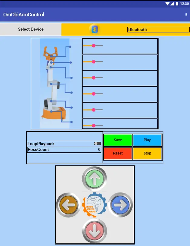
In summary, the app provides the following features:
Bluetooth Connectivity: First, the app connects to the HC-05 Bluetooth module on the OmObiArm. Then, users pair their device and establish a connection via the “Select Device” button. After connecting, the status display changes to “Connected.”
Robotic Arm Control: Six sliders in the app control the arm’s joints, from the base to the gripper. Also, each slider sends a position value to the corresponding servo motor in real time. So when you adjust a slider, the app sends the servo command in the format N,angle\n (for example, 1,90\n to move servo 1 to 90 degrees).
Mobile Platform Control: Four directional buttons (Forward, Backward, Left, Right) drive the rover. Also, a Stop button halts all motors immediately. Then, each button sends its single-character command followed by a newline.
Pose Management: The “Save” button stores the current arm position as a pose (sends v\n). Then, “Play” initiates playback of saved poses (sends l\n). “Reset” clears all saved configurations (sends r\n). In addition, a toggle switch enables or disables looped playback (sends o\n to enable and f\n to disable).
Feedback Display: Finally, at the top, the app shows the current Bluetooth connection status and the number of saved poses.
Building the App Step by Step
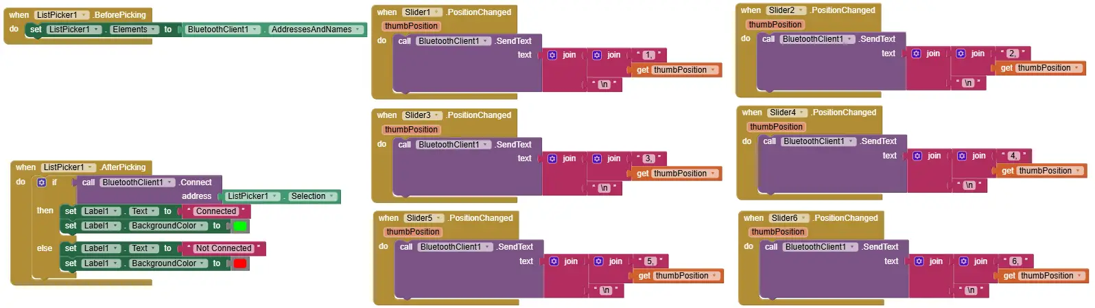
Bluetooth Connection Setup
First, use a ListPicker component in MIT App Inventor. In the “Before Picking” event, populate the list with available paired Bluetooth devices. In the “After Picking” event, attempt a connection to the selected device. After that, update the interface to display a “Connected” status. For a refresher on Bluetooth app building, see our HC-05 Bluetooth module tutorial, which covers the MIT App Inventor Bluetooth setup in detail.
Arm Joint Control with Sliders
Next, add six Slider components, one for each servo. Then, set each slider’s range from 0 to 180. In the “PositionChanged” event for each slider, send the corresponding command string over Bluetooth. For example, Slider 1 sends 1,<value>\n, Slider 2 sends 2,<value>\n, and so on up to Slider 6.
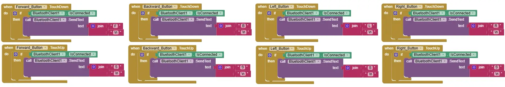
Rover Movement Control
Then, add four directional Button components (Forward, Backward, Left, Right) and one Stop button. Also, in each button’s “TouchDown” event, send the respective command string: F\n for forward, B\n for backward, L\n for left, R\n for right, and S\n for stop. You can also send the stop command on the “TouchUp” event of each directional button to implement hold-to-drive behavior.
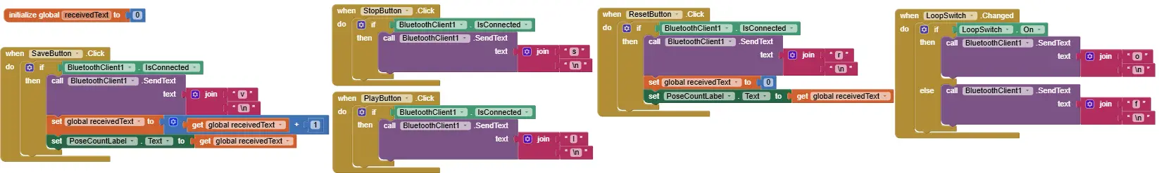
Pose Management Controls
After that, add buttons for Save, Play, Reset, and Stop playback, plus a toggle switch for Loop mode. Also, each button sends its command string: Save sends v\n, Play sends l\n, Reset sends r\n, and Stop sends s\n. Similarly, the Loop toggle sends o\n when enabled and f\n when disabled.
Real-Time Feedback Display
Finally, add Label components to display the Bluetooth connection status and the count of saved poses. Update these labels dynamically as the user connects, saves, and resets poses.
How the App Works in Practice
Connecting to the Robot: First, open the app and tap “Select Device.” Choose the HC-05 module from the list of paired Bluetooth devices. When connected, the status label updates to “Connected.”
Controlling the Robotic Arm: Then, use the six sliders to move the arm’s joints. Because of this, adjustments are sent to the robot in real time over Bluetooth. Each slider independently controls one servo channel.
Managing Poses: To save a pose, position the arm where you want it, then tap “Save” to record the pose. Also, you can repeat this for up to 10 poses. Tap “Play” to replay all saved poses sequentially. Optionally, enable the loop toggle for continuous playback. Tap “Stop” to halt playback at any time. Tap “Reset” to clear all saved poses.
Driving the Rover: Then, use the directional buttons to drive the rover forward, backward, left, or right. Also, tap “Stop” to halt all motors immediately. Remember that the system ignores rover commands during pose playback for safety.
Step 7: Calibration, Testing, and Tuning the OmObiArm
After uploading the code and installing the app, it is time to finally test and calibrate the complete OmObiArm system. Then, follow this sequence to verify each subsystem before attempting full operation.
7.1 Connection Check
To begin with, open the OmObiArmControl app, tap “Select Device,” and pair with the HC-05 module. Then, the HC-05 LED should change from fast blinking (pairing mode) to slow blinking or steady on (connected). The app should then display “Connected.” If the connection fails, verify that the HC-05 has power and that you have enabled Bluetooth on your phone. Note that the default pairing code is usually 1234 or 0000.
7.2 Rover Drive Verification
Next, test each rover movement direction one at a time. Then, tap Forward, Backward, Left, and Right in the app and verify the rover moves in the correct direction. If a motor spins the wrong way, swap the motor wires on the Motor Shield terminal for that motor pair. Also verify that the Stop button immediately halts all movement.
7.3 Servo Calibration
After that, test each servo channel one by one. Then, move Slider 1 slowly and verify that servo 1 (base rotation) responds. Also, repeat for all six sliders. If a servo does not respond, check the PCA9685 channel wiring and confirm the channel matches the code mapping (channels 0, 4, 8, 9, 12, 13). If a servo jitters or buzzes without moving, check the 6 V power supply from the LM2596. You can also adjust the slider range if any servo reaches its mechanical limit before the slider reaches 0 or 180. To do this, modify the PWM mapping values in the code (the map(position, 0, 180, 150, 600) line) to fine-tune the usable range for each servo.
7.4 Pose Save and Play Verification
First, move the arm to a specific position and tap “Save.” After that, move the arm to a different position and tap “Save” again. Now tap “Play” and verify that the arm smoothly replays both saved poses in order. Test “Reset” to clear the poses, then verify that “Play” does nothing when no poses are saved. Test the loop toggle by enabling it and starting playback. The arm should cycle through poses continuously until you tap “Stop.”
7.5 Combined Rover and Arm Stress Test
Once both subsystems work individually, test them together. Then, drive the rover while moving arm sliders. Also, monitor the battery voltage under combined load. If, for example, the robot becomes sluggish, servos jitter, or the Arduino resets, you likely have power supply issues. A fully charged 7.4 V LiPo should supply enough current, but heavily loaded servos (for example, holding a heavy object with the gripper while driving) may cause voltage drops. If this happens, consider using a higher capacity battery or reducing the motor speed in the code.
7.6 Safe Test Sequence
Finally, for a reliable first test, follow this order: (1) power on the robot with the arm in a relaxed position, (2) connect from the app, (3) test rover movement on a flat surface, (4) test each servo slider slowly, (5) test saving and playing two simple poses, (6) test loop mode, (7) test stop and reset, (8) finally test combined driving and arm movement. This step-by-step approach isolates problems and prevents damage.
Troubleshooting Common OmObiArm Issues
If something does not work as expected, then use this troubleshooting guide to identify and fix the most common problems.
HC-05 pairs but the robot does not respond to commands: Verify the HC-05 TXD is connected to Arduino RX (pin 0) and RXD to Arduino TX (pin 1). Also, confirm the baud rate in the code is 9600, which matches the HC-05 default. Then, try opening the Arduino Serial Monitor (with HC-05 disconnected) to verify the code is running and printing the “Waiting for commands” message.
Arduino sketch upload fails: First, disconnect the HC-05 module from pins 0 and 1 before uploading. This is because the HC-05 interferes with the USB serial communication used for uploading. Reconnect it after the upload completes.
Servo and Motor Issues
Servos jitter, buzz, or stall: First, check the LM2596 output voltage. Then, it should be exactly 6 V. If the voltage drops under load, the battery may be low or the LM2596 may not supply enough current. Also, check for loose PCA9685 wiring. Jitter can also result from insufficient power, especially when multiple servos move at the same time.
Rover moves but the arm does not respond: Verify that the PCA9685 SDA and SCL connections to the Arduino Mega (pins 20 and 21) are correct. Also, check that the PCA9685 receives 6 V on its power terminal. Verify the I2C address — the default is 0x40. Run an I2C scanner sketch to confirm that the Arduino detects the PCA9685.
Arm moves but the rover does not respond: Check the motor wiring to the Motor Shield terminals M1 through M4. Also, verify that the Motor Shield sits firmly on the Arduino Mega. Also check that the battery is supplying enough voltage through the Motor Shield power terminals.
Pose and Power Issues
Poses do not save or play correctly: First, verify you are sending the correct commands from the app (v for save, l for play). Also, check the Serial Monitor output for pose count messages. Also, remember the maximum is 10 poses — if you have already saved 10, the system ignores additional saves.
Loop playback does not stop: First, to stop playback, send the “s” command (lowercase) from the app. During loop playback, the system checks the stop command between poses, not during servo movement. Because of this, there may be a short delay before the loop actually stops. Make sure your app sends the correct character.
Voltage drops and erratic behavior under load: In most cases, this means the battery cannot supply enough current for simultaneous motor and servo operation. Therefore, use a fully charged LiPo. If the problem still persists, also consider a higher-capacity battery or powering the rover motors and servo system from separate batteries.
Motors spin in the wrong direction: Then, just swap the two wires on the Motor Shield terminal for the affected motor. In other words, you do not need to change the code.
Frequently Asked Questions (FAQ)
OmObiArm is a DIY mobile robot arm project that combines a four-wheel Bluetooth-controlled rover (based on the OmObi platform) with a 6-DOF robotic arm (based on the OmArm design). Also, it is controlled wirelessly from an Android phone via Bluetooth and an Arduino Mega.
This project is designed for the Arduino Mega 2560 because it has more memory, more I/O pins, and extra hardware serial ports. The Mega is recommended because the combined code and pose storage may exceed the Uno’s SRAM. If you must use an Uno, reduce the number of saved poses.
OmObiArm uses the HC-05 Bluetooth module for wireless communication. Basically, the HC-05 is a classic Bluetooth (SPP) module that works at 9600 baud by default and is easy to pair with Android devices. For a complete guide on using the HC-05 and HC-06 modules, see our Arduino HC-05 / HC-06 Bluetooth module tutorial.
The Adafruit Motor Shield uses several of the Arduino’s PWM pins, so the PCA9685 communicates over I2C instead (using only SDA and SCL) and provides 16 independent PWM channels. It also powers all servos from a separate 6 V supply, which protects the Arduino.
Currently, you can save up to 10 poses. Each pose stores the PWM values for all six servos in Arduino RAM. Poses are lost when power is removed. You can increase the limit in the code or use EEPROM for persistent storage.
More common questions
Basically, the HC-05 uses Bluetooth Classic (SPP), which iPhones do not support natively. To control the robot from iOS, replace the HC-05 with a BLE module (like the HM-10 or ESP32 with BLE) and update the Arduino code and app accordingly.
This is a safety feature. During pose playback, the arm uses blocking servo commands. If the rover could drive at the same time, it might move unexpectedly and cause collisions. The code stops the rover motors before playback starts.
A 7.4 V 2S LiPo battery with at least 5300 mAh is recommended. Overall, the 7.4 V nominal voltage works well for both the DC motors (via the Motor Shield) and the LM2596 step-down converter. Higher capacity batteries provide longer run times and better current handling during combined rover and arm operation.
Servo speed depends on two code constants: stepDelay and stepSize. Increasing stepDelay slows them down. Also, increasing stepSize makes movement faster but less smooth. The defaults (10 ms delay, 1 unit step) give moderate, smooth movement.
Yes. Indeed, the Arduino Mega has plenty of free I/O pins for sensors like HC-SR04 ultrasonic sensors, IR sensors, or even a camera module. In fact, the next planned upgrade for OmObiArm adds four ultrasonic sensors for obstacle avoidance.
The 3D-printable STL files are available on Cults3D and in our OmArTronics Shop. The complete Arduino source code and MIT App Inventor project file are available on GitHub.
Resources and Next Projects
Project Files
- GitHub Repository — Complete Arduino code and MIT App Inventor project file for OmObiArm.
- Cults3D STL Files | OmArTronics Shop — Downloadable 3D-printable parts for the OmObiArm chassis, arm links, and gripper.
Related OmArTronics Tutorials
- OmObi: Building the Bluetooth-Controlled Robot Car — The rover base project that OmObiArm builds upon.
- OmArm: DIY 6-DOF Robotic Arm with Bluetooth Control — The robotic arm project that OmObiArm integrates.
- DIY 6-DOF Robotic Arm — 3D Print, Wire, and Program — The original potentiometer-controlled version of the robotic arm.
- Arduino HC-05 / HC-06 Bluetooth Module Complete Tutorial — Essential guide for understanding Bluetooth communication with Arduino.
- Arduino Servo Motor Control Guide: SG90, PWM, and PCA9685 — Learn servo control fundamentals and PCA9685 driver usage.
- Arduino Programming Basics: Complete Beginner Guide — Start here if you are new to Arduino programming.
- Advanced Autonomous Robot Car with Arduino Mega and Ultrasonic Sensors — Similar project using the same motor shield and Arduino Mega with autonomous capabilities.
- L298N Motor Driver with Arduino: DC Motor Control Guide — Alternative motor driver tutorial for understanding H-bridge motor control.
Suggested Next Upgrades for OmObiArm
- Ultrasonic obstacle avoidance: Add four HC-SR04 sensors to enable autonomous navigation while the arm performs tasks. See our HC-SR04 ultrasonic sensor tutorial and Arduino radar project for inspiration.
- EEPROM pose storage: Save poses to EEPROM so they persist across power cycles, allowing the robot to remember its programmed tasks.
- Speed control: Add variable speed control for the rover using PWM speed adjustments and app sliders instead of fixed maximum speed.
- Camera and computer vision: Mount a camera module for visual object detection and autonomous pick-and-place operations.
- WiFi upgrade: Replace the HC-05 with an ESP32 for WiFi-based control, enabling web browser control or integration with home automation systems.
Conclusion
So if you have followed this tutorial from start to finish, you now have a working Bluetooth-controlled mobile robot arm built from scratch. Now, your OmObiArm can drive in all directions, move a 6-DOF robotic arm, save and replay arm poses, and loop automated sequences, all controlled wirelessly from your Android phone.
During this project, you also picked up hands-on experience with 3D design and printing, mechanical assembly, electronics wiring, Arduino programming, I2C servo control with the PCA9685, DC motor control with the Adafruit Motor Shield, Bluetooth communication with the HC-05, and Android app development with MIT App Inventor. Ultimately, all of that carries over directly into more advanced robotics and automation projects.
In the next project, we also plan to add four ultrasonic sensors to OmObiArm for obstacle avoidance and autonomous object detection, so the arm can find and grasp objects on its own. So stay tuned to OmArTronics for the next upgrade!
Download the 3D Print Files (STL)
Also, all 3D-printable STL files for this project are available for download. You can get them from our shop or browse them on Cults3D:
- OmArTronics Shop: Download project files from OmArTronics — Get the complete project package including STL files, wiring diagrams, and source code delivered to your email.
- Cults3D: View on Cults3D — Browse and download the 3D model files on Cults3D.
Hi OmArTronics plus Team,
Hope all is well with you!
This is Ashley from JLCMC, a sub-brand of JLCPCB. We are dedicated to building a global one-stop-shop service. There are more than thousands of mechanical components to suit different usage scenarios and needs.
We’ve been impressed by your hands-on approach and creative DIY projects, especially your work with robotic arms. Your focus on practical, innovative solutions aligns perfectly with our mission at JLCMC to provide high-quality mechanical components. We believe a collaboration would be mutually beneficial, as your audience’s interest in robotics and automation closely matches the solutions we offer. Partnering with you would allow us to introduce our precision parts to a tech-savvy community eager for smart, efficient technologies.
We would be happy to provide you with our products for your use, if you are interested or if you happen to need to update your components or have any other questions, please feel free to contact us!
Thanks for your time and I’m looking forward to hearing from you!
Best regards,
Ashely