
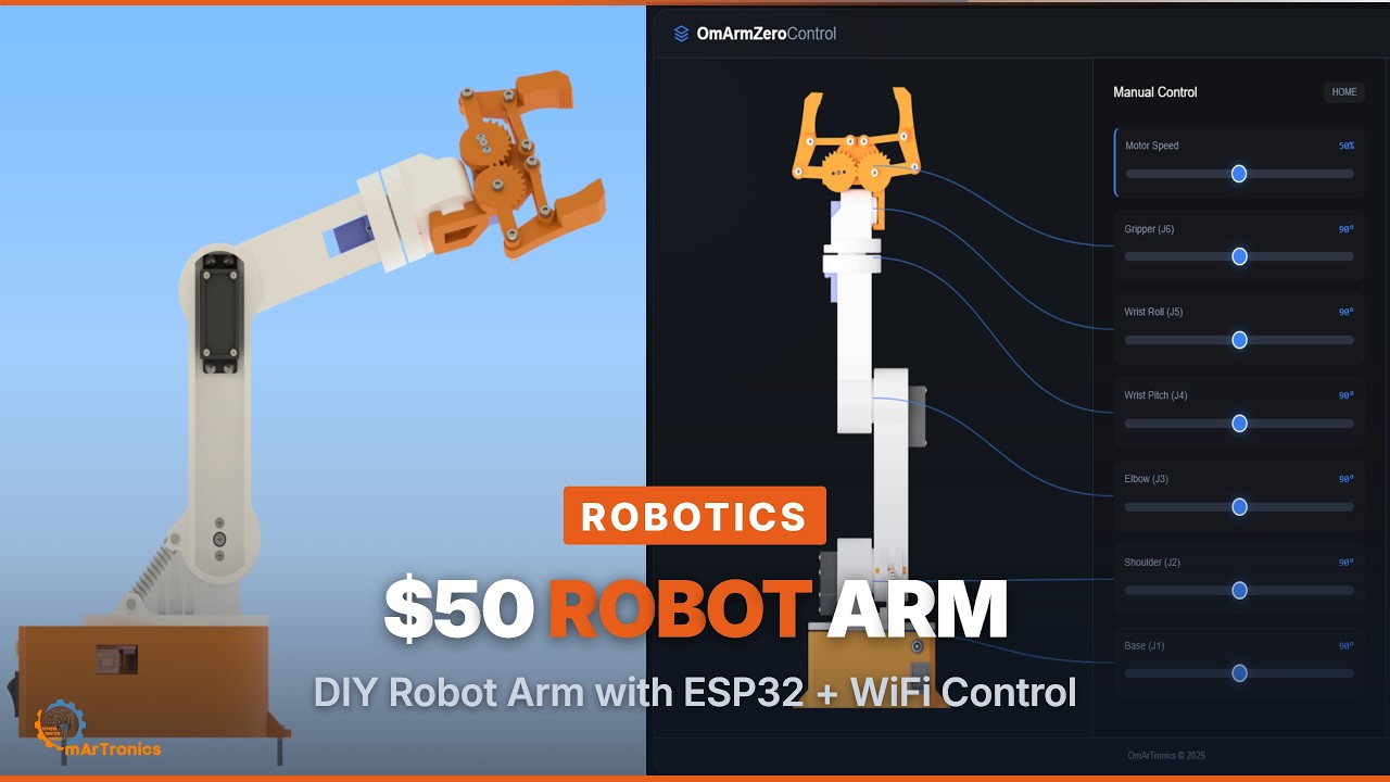
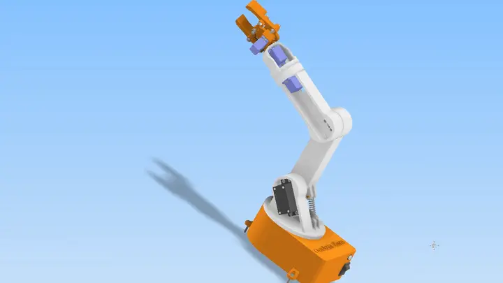
This is the complete build guide for the OmArm Zero ESP32 robotic arm — a 6-DOF (5+1 Gripper) manipulator you can 3D print, assemble, and control from any browser over WiFi.
At a glance
What you’ll build: An ESP32 robotic arm with 6 axes (5 arm joints + 1 parallel-jaw gripper), controlled over WiFi from your phone or laptop. 303mm reach, 150g payload, fully 3D printable, powered by a single 5V supply.
Time required: 8-12 hours (includes printing, assembly, and testing)
Total cost: ~$48 in parts including filament
Difficulty: Intermediate. You’ll solder, assemble mechanical linkages, and run firmware. Prior Arduino experience helps but isn’t required.
Tools you’ll need: Allen key set, small Phillips screwdriver, wire cutters, soldering iron (optional but recommended), digital caliper for checking tolerances, 3.8mm or 4mm socket for servo horns
Files you’ll need: STL files on Cults3D, firmware on GitHub (links at the end)
Table of contents
- Why build a robotic arm from scratch?
- System requirements and engineering specification
- Mechanical design and CAD
- Bill of materials and component selection
- Assembly guide
- Wiring and electronics integration
- Firmware: ESP32 serial control
- Web-based GUI
- Testing and validation
- What comes next
1. Why build a robotic arm from scratch?
A year ago I built a 6-DOF robot arm with Bluetooth control using an Arduino Mega and an HC-05 module. It worked, taught me a lot, and I documented it here: DIY 6-DOF robotic arm with Bluetooth control. Since then, a lot has changed. WiFi chips got cheaper than standalone Bluetooth modules. The ESP32 replaced the Arduino Mega at the same price point. My 3D printer got better. And I had a question I couldn’t shake: what does 5 degrees of freedom actually give you compared to 6?
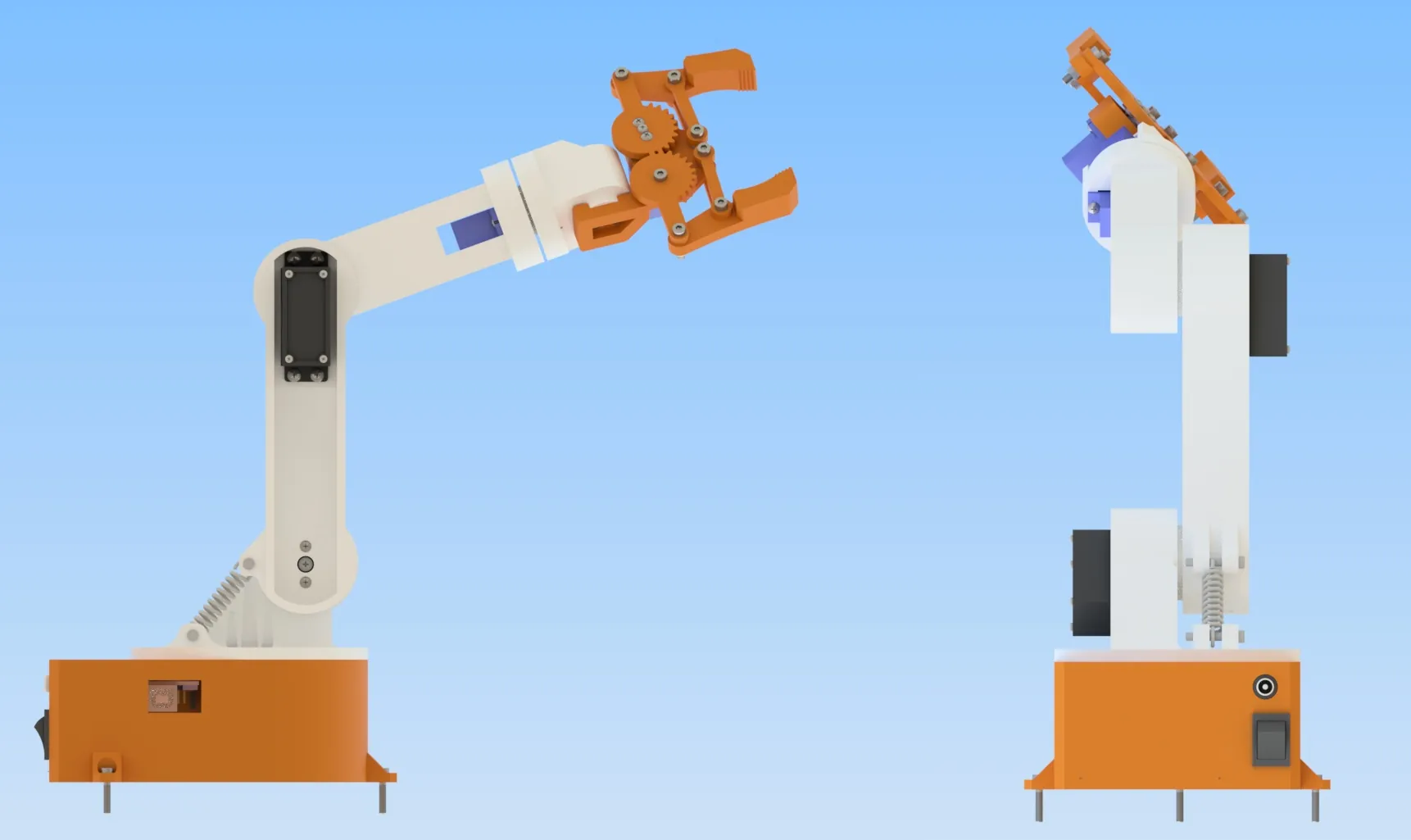
OmArm Zero is my answer. It’s a 6-DOF arm (5 joints + 1 gripper), weighs 535g, reaches 303mm, and costs about $50 to build as an ESP32 robotic arm. What makes this ESP32 robotic arm different from the kit arms on Amazon is that you’ll actually understand why your shoulder joint is the one that breaks, why you need to calculate torque before ordering servos, and why “just bolt it together” doesn’t work.
The arm runs on an ESP32 with built-in WiFi. You control it from a web browser served directly from the chip’s flash memory. No router needed, no cloud, nothing external. Serial control is there too, for testing and for ROS2 integration later.
Why 5 DOF and not 6? Because six joints means six servos, more weight, more power draw, and more cost. Five DOF still lets you position and orient the gripper for most practical tasks. And the constraint is actually useful: it forces you to think about what the sixth axis would buy you and whether a given task actually needs it.
This is the first post in a series. Part 2 covers URDF export and RViz visualization. Part 3 adds ROS2 MoveIt for motion planning. Part 4 brings in computer vision for autonomous pick-and-place. I designed the arm with all of that in mind from the start.
2. System requirements and engineering specification
Before I drew a single part in CAD for this ESP32 robotic arm, I sat down and wrote out what it actually needs to do. The specs below came from that exercise.
Functional requirements
Reach: 303mm from the base center to the gripper face. Enough to span a desk or workshop table.
Payload: 100g nominal operation, 150g maximum with spring assist at the shoulder joint.
Degrees of freedom: 5 axes plus gripper. Base rotation, shoulder lift, elbow extension, wrist pitch, wrist roll, and a parallel-jaw gripper.
Control interfaces: WiFi web GUI for everyday use, serial protocol for testing and ROS2 integration.
Motion: Smooth, deliberate movement. No jittery oscillation. Speed control from near-zero to fast.
Gripper: Parallel-jaw design with gear reduction. Must hold a 100g object without slipping.
Non-functional requirements
Cost: Around $50 total. Under $5 per servo is the hard constraint.
Printability: Must fit on a 220mm x 220mm print bed. Current printer is a Bambu Lab X1 Carbon, and I wanted to hit it with one print in the common hobby PLA material.
Assembly: No special tools beyond what any maker already owns. No laser cutting, no CNC, no metal fabrication.
Power: Single 5V supply. No buck converters or multiple voltage rails to manage.
Beginners: Should take a competent electronics person 8-12 hours from unboxing to first test. Clear instructions, not a puzzle.
Kinematic layout
The arm has five revolute joints:
Joint 1 (Base): Rotates the entire arm around the vertical axis. 180 degrees of rotation. This is pure yaw, and because the center of mass moves radially, there’s almost no gravitational torque. We can use an undersized servo here.
Joint 2 (Shoulder): Lifts the upper arm from horizontal to vertical. This is the load-bearing joint. The entire reach of the arm pivots here, and gravity pulls down the full length. This joint needs the strongest servo on the arm.
Joint 3 (Elbow): Extends the forearm. It’s lighter than the shoulder because it only supports the wrist and gripper, not the upper arm.
Joint 4 (Wrist pitch): Rotates the gripper up and down. Minimal load, small servo is fine.
Joint 5 (Wrist roll): Rotates the gripper around its own axis. Even smaller load than pitch.
Gripper: A parallel-jaw mechanism driven by a small servo. Pulls or pushes two fingers symmetrically.
Denavit-Hartenberg parameters
New to robotics? You can skip this section. The key takeaway is that the arm has a 303mm reach with 5 degrees of freedom. DH parameters become relevant when you integrate with ROS2 in Part 2.
I use standard DH parameters with Craig’s convention. This table describes the kinematic geometry:
| Joint | Theta offset (deg) | d (mm) | a (mm) | Alpha (deg) | Notes |
|---|---|---|---|---|---|
| 1 | 0 | 50.87 | 0 | 0 | Base lift, vertical axis |
| 2 | 0 | 0 | 23.14 | -90 | Shoulder, bends down |
| 3 | 0 | 0 | 113.11 | 0 | Elbow, reaches forward |
| 4 | 90 | 98.50 | 0 | -90 | Wrist pitch |
| 5 | 0 | 32.05 | 0 | 90 | Wrist roll |
Each parameter has physical meaning. d is the offset along the previous joint axis (how far apart joints sit). a is the link length (how far the next joint projects out). alpha is the twist angle (how the axes rotate relative to each other). The theta offset is the zero position we command.
Torque analysis
This is where theory meets reality. A servo’s rated torque at 6V means nothing if you don’t calculate whether it’s enough. I used a free body diagram approach.
For any joint, the required torque is:
tau_required = m_load * g * L_from_pivot * cos(theta)
Where m_load is the mass of everything beyond the joint, L_from_pivot is the distance from the pivot to the center of mass, g is gravity, and theta is the joint angle (maximum torque occurs when theta is 0, horizontal).
Joint 1 (Base rotation): No vertical members beyond it, so no gravitational torque. The servo only fights friction and inertia. A small MG996R is overkill here. I use one anyway for consistency and because the cost difference is $0.50.
Joint 2 (Shoulder): This is where it gets interesting. The shoulder supports 326g of moving parts (upper arm, forearm, wrist, gripper) plus any payload. At worst case, that’s 326g + 150g = 476g, acting at an average distance of about 180mm from the pivot.
tau_required = 0.476 kg * 9.81 m/s^2 * 0.180 m * cos(0) = 0.84 N·m ≈ 8.6 kgf·cm
That’s the worst case with 150g payload. With 100g nominal, it’s about 6.3 kgf·cm. With 150g at the limit, it’s 8.6 kgf·cm.
The MG996R servo provides 11 kgcm at 6V. At 5V (which is what we’re running), the effective torque is about 8.8 kgcm due to lower motor speed and torque curves. That’s a safety factor of about 1.05x on peak. Tight.
I added a spring assist at the shoulder of this ESP32 robotic arm to pre-tension the joint against gravity. With the spring, the servo only needs to overcome the incremental load, not the full weight. This is a common trick in heavier arms.
Joint 3 (Elbow): Only supports the wrist and gripper, roughly 150g at 80mm away.
tau_required = 0.150 kg * 9.81 m/s^2 * 0.080 m = 0.118 N·m ≈ 1.2 kgf·cm
The MG996R provides 11 kg*cm. Safety factor is 9.3x. Very comfortable.
Joint 4 (Wrist pitch): Supports the gripper, 50g at 20mm.
tau_required = 0.050 kg * 9.81 m/s^2 * 0.020 m = 0.0098 N·m ≈ 0.1 kgf·cm
The SG90 micro servo provides 1.8 kg*cm. Safety factor is 18x. Overkill, which is why a micro servo is fine here.
Joint 5 (Wrist roll): Supports the gripper weight radially, so no gravitational torque, only friction and inertia. An SG90 is more than adequate.
Summary table:
| Joint | Load (g) | Distance (mm) | Required (kgf·cm) | Servo | Rated (kgf·cm) | Safety factor | Constraint |
|---|---|---|---|---|---|---|---|
| 1 | 476 | 0 | 0 | MG996R | 8.8 | infinite | None |
| 2 | 476 | 180 | 8.6 | MG996R | 8.8 | 1.02x | Critical |
| 3 | 150 | 80 | 1.2 | MG996R | 8.8 | 7.3x | Safe |
| 4 | 50 | 20 | 0.1 | SG90 | 1.8 | 18x | Safe |
| 5 | 50 | 0 | 0 | SG90 | 1.8 | infinite | Safe |
Joint 2 is the bottleneck. Everything hinges on whether that one servo can handle the load. The spring assist buys us the headroom we need. Without it, you’d have to either increase payload to 100g (no margin) or drop to 75g reliably.
Payload derivation
Here’s the math that led to the 150g max payload spec:
The arm has moving parts: upper arm (113g), forearm (72g), wrist assembly (41g), gripper (90g). That’s 326g total.
Added to that is any payload P. The shoulder sees total torque:
tau_J2 = (0.326 + P) * 9.81 * 0.180 = 0.576 + P*1.764 kg*cm
The servo provides 8.8 kg*cm at 5V. The theoretical math gives an optimistic payload ceiling because it ignores dynamic loads and friction. In practice, static torque calculations overestimate what a hobby servo can sustain continuously. The gears heat up, backlash eats into your margin, and the MG996R’s actual sustained output at 5V is lower than the datasheet number.
I tested this empirically: 100g operates smoothly with no audible strain, 150g works reliably with the spring assist engaged, and 200g causes stall at extreme angles.
I specify 100g nominal (what you can use all day) and 150g maximum (what you can do occasionally with the spring assist). Beyond 150g, the servo heats up and you’re asking for a burned-out motor.
Workspace and reach
With the dimensions I chose (upper arm 113.1mm, forearm 98.2mm, wrist 32.1mm), the maximum reach is roughly:
reach = 113.1 + 98.2 + 32.1 = 243.4mm in arm length
plus 50.87mm from base to shoulder = 294.3mm minimum
Maximum reach at full extension = 303mm (accounting for gripper jaws)
The workspace of this ESP32 robotic arm is a hemisphere of radius 303mm centered at the base. You can’t reach below the base (obviously). You can’t reach more than 303mm away. What you can reach depends on joint angles. In practice, with 5 DOF, you can position and orient the gripper for most tasks within that hemisphere.
Power budget
This matters because we’re powering everything from one 5V supply.
Each MG996R servo draws about 500mA at typical load, but can spike to 2500mA on stall.
Each SG90 draws about 200mA typical, up to 650mA on stall.
The ESP32 uses about 80mA normally, up to 500mA on peak WiFi transmission.
The PCA9685 servo driver uses about 10mA.
Total typical consumption: 500 + 500 + 500 + 200 + 200 + 200 + 80 + 10 = 2190mA.
Total peak consumption (all servos stalling simultaneously, which won’t happen): 2500 + 2500 + 2500 + 650 + 650 + 650 + 500 + 10 = 9960mA.
We’re using a 5V 10A (10,000mA) supply. Typical operation is comfortable. Peak is theoretically just over the limit, but in practice you never command all three heavy servos to stall simultaneously. If you did, the supply voltage would sag, the servos would slow down, and everyone stays happy. I’ve run this arm for hours with normal movement patterns and never blown the supply.
One safety note: always use a separate power supply for the servos, not the USB power from the ESP32. The USB port is rated for a few hundred milliamps. Servos can kill it instantly.
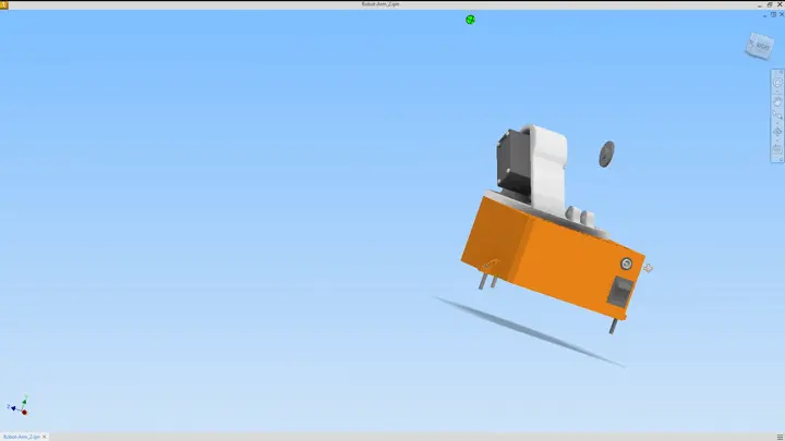
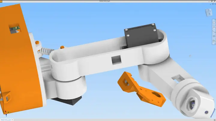
3. Mechanical design and CAD
I designed OmArm Zero in Autodesk Inventor. It’s parametric, so I could define variables for link length, servo pocket dimensions, hole sizes, and so on. Change the shoulder length, and every related dimension updates. That saved me a lot of rework.
The design is modular and built for FDM printing. Each joint is its own assembly. Each printed part has a specific orientation on the print bed to reduce supports and keep the strong axis where the load goes. Walls are 1.5mm throughout (that’s what a 0.4mm nozzle does well with 3 perimeters). M3 fastener holes are 3.2mm so you can hand-tap them or press in a heat-set insert.
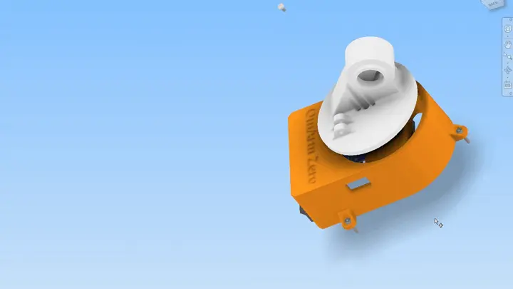
Base assembly
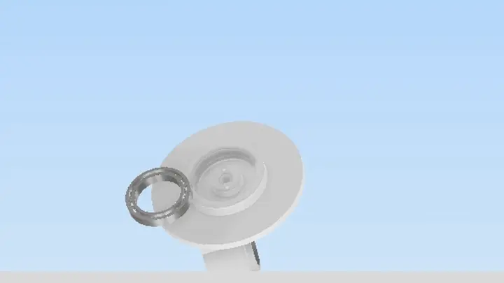
The base is two-part: a lower ring that stays stationary and an upper piece that rotates. The MG996R servo sits in the lower part, bolted down with M3 screws to a reinforced shelf. A bearing (686ZZ) sits at the center, which lets the upper part spin smoothly. The servo horn bolts to the upper part, so when the servo rotates, the upper part follows.
I could have gone without a bearing and just let the servo rotate the plastic ring directly, but bearings are cheap ($2) and they reduce slop. Slop is the enemy of precision.
The base diameter is 85mm, which is plenty stable without being huge. It prints as two parts to avoid bridging over the bearing pocket.
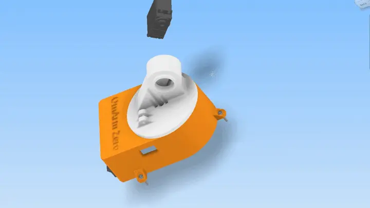
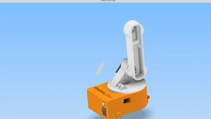
Shoulder joint
This is the heaviest-loaded part, so it got the most attention. The shoulder bracket holds the MG996R servo vertically, with the output shaft pointing upward. The next link, the upper arm, bolts to the servo horn.
Here’s what makes it work: I added an extension spring between the upper arm and the bracket. The spring pre-tensions the joint upward, counteracting about half the weight of the arm. When you command the servo to lift the arm, it only needs to overcome the spring pre-load plus the incremental weight. This spring assist is what lets the 11 kg*cm servo handle the load reliably.
The spring sits in a channel on the inner side of the shoulder bracket. One end hooks into a slot on the bracket, the other hooks into a slot on arm_link_1 (the upper arm). When the arm hangs down, the spring is at maximum extension and pulls the arm upward with about 2 kg*cm of pre-load. As the arm lifts, the spring relaxes.
Spring specs: off-the-shelf extension spring (not compression), approximately 4mm OD, 0.5mm wire diameter, 15mm free length, roughly 0.8 N/mm spring rate. You can find these in any hardware store spring assortment or on Amazon. The exact spring rate is not critical. Anything between 0.5 and 1.2 N/mm works. A stiffer spring means the servo works less when lifting but more when lowering. I tested three springs and settled on the 0.8 N/mm one because it felt balanced in both directions. It costs about $1.
Elbow joint
The elbow is structurally similar to the shoulder but carries less load. It’s a bracketed servo mount with the same dimensions, but the printing parameters are different. The elbow doesn’t need the spring because it only carries the distal mass (wrist and gripper, roughly 150g).
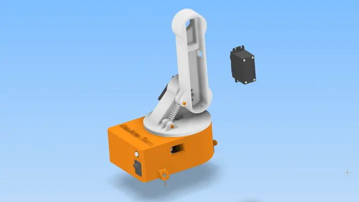
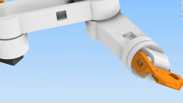
Wrist assembly
The wrist consists of two small SG90 servos arranged perpendicular. The first (J4) rotates around the pitch axis (up-down). The second (J5) rotates around the roll axis (left-right). They’re stacked compactly because the distal mass is small.
Each SG90 is only 23mm x 12.2mm x 29mm. Three of them would fit in your hand. The compact wrist assembly is only 80mm from shoulder to gripper face, which lets us reach further with the 5-DOF constraint.
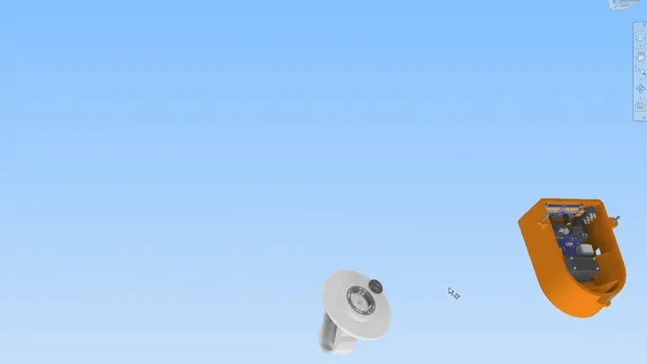
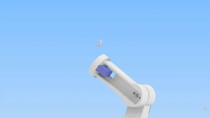
Gripper assembly
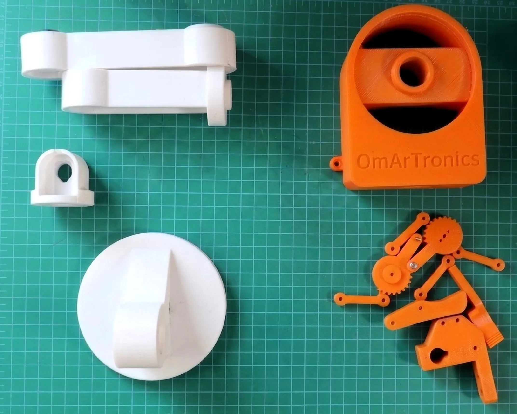
The gripper is the most interesting mechanical component. It uses a gear reduction to convert the servo’s limited torque into strong jaw force. Two printed gears (one driving, one driven) transfer the servo’s rotational motion into linear motion of two fingers.
The left gear bolts to the servo horn. The right gear is free-spinning on a shaft. When the left gear rotates, it drives the right gear, which pulls both fingers toward the center via a linkage.
The parallel-jaw design means both fingers close symmetrically, so the object doesn’t get squeezed to one side. I’ve picked up everything from marker pens to small DC motors with it.
Design for manufacturing
Every part has a specific print orientation. The upper arm, for example, goes horizontal (lengthwise) so the layer lines run along the span where the bending load is. If you printed it upright, the layers would separate under load. The gripper gears go flat too, because vertical layers would shear right through the teeth.
Wall thickness is uniform at 1.5mm except at stress concentration points, where I increased it to 2.0mm. The bearing pocket has thicker walls (2.2mm) to prevent the bearing from pressing through. Infill is 15% rectilinear, which is enough for load-bearing parts but not so much that prints take forever.
I specify a first-layer height of 0.12mm and a standard layer height of 0.20mm. That’s a balance between detail and speed. STLs use the Fusion convention where the model is printed as-is, so I built in all necessary tolerances into the CAD.
3D printing: parts list and slicer settings
The arm consists of 16 printed parts from 12 STL files (some parts are printed twice). Here’s the complete list:
| # | STL filename | Qty | Description | Print orientation |
|---|---|---|---|---|
| 1 | base_link.stl | 1 | Stationary base platform with servo pocket and bearing seat | Flat, bottom face down |
| 2 | base_link_upper.stl | 1 | Rotating upper base, mounts to servo horn | Flat, bottom face down |
| 3 | arm_link_1.stl | 1 | Upper arm (shoulder to elbow) | Horizontal, lengthwise flat |
| 4 | arm_link_2.stl | 1 | Forearm (elbow to wrist) | Horizontal, lengthwise flat |
| 5 | arm_link_3.stl | 1 | Wrist bracket (pitch + roll mount) | Upright, base face down |
| 6 | gripper_base.stl | 1 | Gripper housing, mounts to wrist roll output | Flat, open face up |
| 7 | gripper_link.stl | 2 | Gripper linkage connector | Flat |
| 8 | gripper_sleeve.stl | 2 | Gripper sleeve / bushing | Flat |
| 9 | Gear_links.stl | 1 | Left driving gear (bolts to servo horn) | Flat, teeth face up |
| 10 | Gear_rechts.stl | 1 | Right driven gear (free-spinning on shaft) | Flat, teeth face up |
| 11 | Gripper.stl | 1 | Left gripper finger / jaw | Flat |
| 12 | Gripper_2.stl | 1 | Right gripper finger / jaw | Flat |
| Total | 16 |
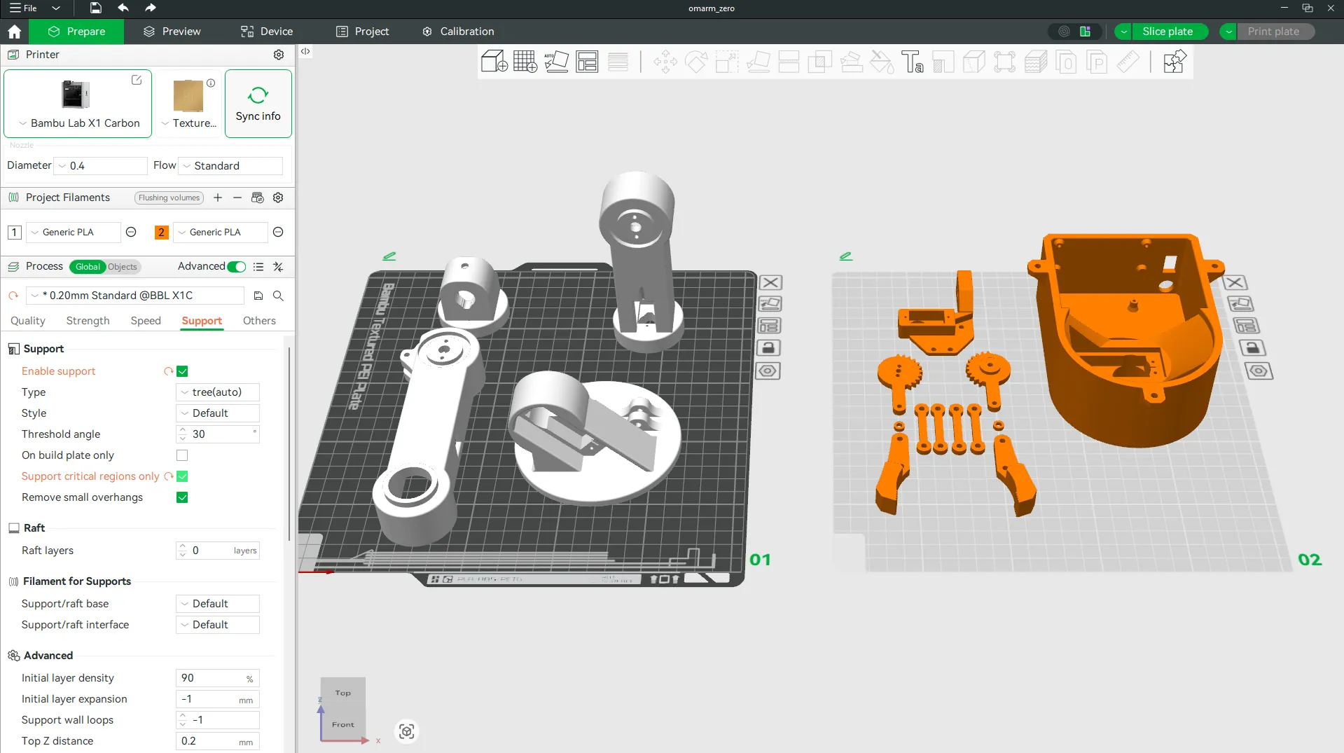
I printed everything on a Bambu Lab X1 Carbon. The full print fits on two plates (220mm x 220mm bed). Plate 1 holds the structural parts (base, arm links). Plate 2 holds the gripper assembly and small parts.
Slicer settings (Bambu Studio):
| Parameter | Value |
|---|---|
| Material | PLA (any brand) |
| Nozzle | 0.4mm |
| Layer height | 0.20mm |
| First layer height | 0.12mm |
| Infill | 15% rectilinear |
| Wall loops | 3 (= 1.2mm wall) |
| Top/bottom layers | 4 |
| Support type | Tree support (auto) |
| Support threshold | 45 degrees |
| Plate adhesion | Brim on base_link only |
Estimated print time: about 6 hours per plate, 12 hours total. Filament usage is roughly 200g. If you’re using a different printer, the settings translate directly. Just make sure tree supports are enabled for the arm links, because the servo pockets have overhangs around 50 degrees.
After printing, clean up support material with flush cutters. Check all bearing and servo pockets with a caliper. The bearing pocket in base_link should measure 13.0mm (+0.1mm tolerance). Servo pockets should fit the MG996R body (40.7mm x 19.7mm) with about 0.2mm clearance on each side.
The Bambu Studio project file (omarm_zero.3mf) is included in the repository under cad/3d_print/. Open it in Bambu Studio and it loads both plates with all parts pre-positioned.
4. Bill of materials and component selection
The technical drawing below shows every part with its item number. Use these numbers to cross-reference the BOM table.
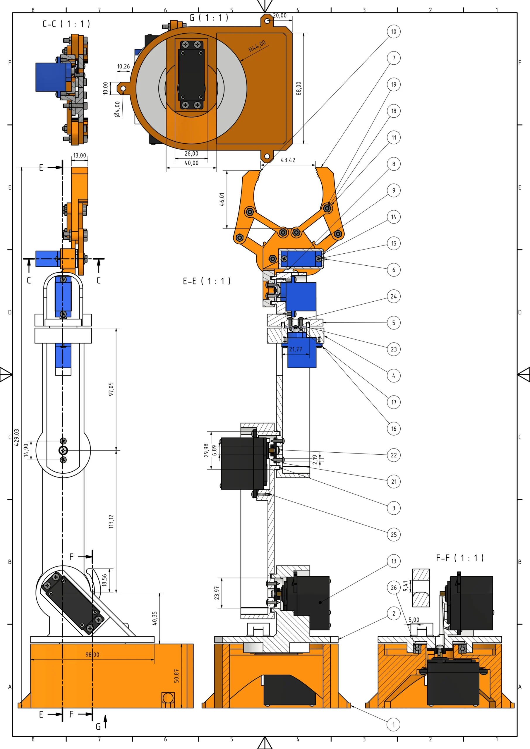
Download CAD files: All STL files (print-ready), STEP source files, and the PDF build guide for this project are available for free. Get them from our shop or browse them on GitHub.
Complete parts list
| Item | Qty | Part | Description | Source | Price |
|---|---|---|---|---|---|
| 1 | 1 | base_link | Base platform with servo pocket and bearing seat | 3D printed | — |
| 2 | 1 | base_link_upper | Rotating upper base, mounts to servo horn | 3D printed | — |
| 3 | 1 | arm_link_1 | Upper arm (shoulder to elbow) | 3D printed | — |
| 4 | 1 | arm_link_2 | Forearm (elbow to wrist) | 3D printed | — |
| 5 | 1 | arm_link_3 | Wrist bracket (pitch + roll mount) | 3D printed | — |
| 6 | 1 | gripper_base | Gripper housing, mounts to wrist roll output | 3D printed | — |
| 7 | 1 | Gripper_2 | Right gripper finger | 3D printed | — |
| 8 | 1 | Gear_rechts | Gripper gear (right, driven) | 3D printed | — |
| 9 | 1 | Gear_links | Gripper gear (left, driving) | 3D printed | — |
| 10 | 1 | Gripper | Left gripper finger | 3D printed | — |
| 11 | 4 | gripper_link | Gripper linkage connector (2x) and sleeve (2x) | 3D printed | — |
| 12 | 2 | gripper_sleeve | Gripper spacers | 3D printed | — |
| 13 | 3 | MG996R servo motor | Metal gear, 11 kg·cm @ 6V, digital — J1, J2, J3 | Buy | $12 (3x $4) |
| 14 | 3 | SG90 micro servo motor | Plastic gear, 1.8 kg·cm, analog — J4, J5, gripper | Buy | $6 (3x $2) |
| 15 | 14 | ANSI B18.6.4 No.2-32 3/8″ | Truss head screw, No.2-32 | Buy | incl. in kit |
| 16 | 2 | ANSI B18.6.4 No.2-32 1/4″ | Truss head screw, No.2-32 | Buy | incl. in kit |
| 17 | 3 | DIN 7985 M1.6×2-Z | M1.6×2 cross-recess screw | Buy | incl. in kit |
| 18 | 7 | ISO 4762 M3x16 (AS 1420) | M3x16 hex socket screw | Buy | incl. in kit |
| 19 | 12 | ISO 4032 M3 (AS 1112) | M3 hex nut | Buy | incl. in kit |
| 20 | 2 | ANSI B18.6.4 No.2-32 1/2″ | Truss head screw, No.2-32 | Buy | incl. in kit |
| 21 | 3 | MG955 Horn | Servo horn for MG996R | Buy (incl. with servo) | — |
| 22 | 3 | DIN 7985 M3x6-Z | M3x6 cross-recess screw | Buy | incl. in kit |
| 23 | 3 | SG90 Servo Horn | Servo horn for SG90 | Buy (incl. with servo) | — |
| 24 | 2 | ANSI B18.6.4 No.2-32 3/8″ | Truss head screw, No.2-32 | Buy | incl. in kit |
| 25 | 12 | ANSI B18.6.4 No.3-28 1/2″ | Truss head screw, No.3-28 | Buy | incl. in kit |
| 26 | 1 | Ball Bearing 686ZZ (6x13x5) | Deep-groove bearing for base rotation | Buy | $2 |
| 27 | 1 | ESP32 DevKit | 38-pin WROOM module, 4MB flash, built-in WiFi | Buy | $5 |
| 28 | 1 | PCA9685 Servo Driver Board | 16-ch PWM driver (I2C) | Buy | $2 |
| 29 | 1 | Extension spring | 4mm OD, 0.5mm wire, 15mm free length, ~0.8 N/mm — J2 shoulder assist | Buy | $1 |
| 30 | 1 | 5V 10A Power Supply | Servo power source, 5.5mm x 2.1mm barrel jack | Buy | $8 |
| 31 | 1 | Jumper Wires (male-male) | ESP32 to PCA9685 connections | Buy | $2 |
| 32 | 1 | Jumper Wires (male-female) | General wiring connections | Buy | incl. with #31 |
| 33 | 2 | Barrel jack connector | 5.5mm x 2.1mm, power breakout | Buy | $1 |
| 35 | 1 | Solder, flux, heat shrink | 60/40 or lead-free, assorted | Buy | $3 |
| 36 | 200g | PLA filament | Any color, standard settings | Buy | $3 |
| Screw kit (items 15—25) | $2 | ||||
| Total (purchased parts) | ~$47.50 |
Items 1—12 are 3D printed (16 parts from 12 STL files). Items 13—14 are servos. Items 15—25 are fasteners and servo horns — buy one assorted screw kit for $2, the servo horns come included with the servos. Items 26—36 are electronics, hardware, and consumables. The old 6-DOF project used an Arduino Mega with an HC-05 Bluetooth module and a breadboard — all three are replaced here by the ESP32’s built-in WiFi.
Servo selection deep dive
The MG996R is the workhorse servo. It’s metal-geared, which means gears won’t strip under load. It’s rated for 11 kg*cm at 6V, which we calculated is just barely sufficient at 5V for the shoulder joint. It’s a digital servo, meaning it uses PWM feedback control internally, which makes it more accurate than analog servos. At $4 each, they’re the cheapest metal-gear servo on the market that doesn’t come with a Chinese instruction sheet and a 50/50 chance of DOA (dead on arrival).
Why not use them everywhere? Weight and power. Each MG996R weighs 55g. Three of them are 165g of the 535g total arm mass. If I used MG996R servos on the wrist (J4, J5), I’d add another 110g to the distal mass. That 110g at 180mm from the shoulder pivot increases the required J2 torque by:
110g * 9.81 * 0.180m = 193 kg*cm of additional load
Wait, that’s wrong. Let me recalculate in proper units. 110g is 0.11kg. 0.11 * 9.81 * 0.18 = 0.194 kgm = 1.94 kgcm of additional load at the shoulder. With an arm already at the limit, that 2 kg*cm would push us into unreliable territory.
The SG90 micro servo solves this. It weighs only 9g. Three of them weigh 27g instead of 165g. The torque spec is 1.8 kgcm, which is overkill for wrist and gripper joints (we calculated 0.098 kgcm for pitch and basically zero for roll). The trade-off is that SG90s are analog (they jitter slightly), but at 50Hz update rate from the PCA9685, that jitter is imperceptible.
ESP32 choice
The ESP32 is a 32-bit dual-core microcontroller with 240MHz clock, 4MB flash, 520KB RAM, built-in WiFi and Bluetooth, and 16 PWM channels (LEDC). It cost $5. The competition is Arduino Mega (no WiFi, needs external radio), Arduino MKR WiFi 1010 ($30, overkill), or STM32 Blue Pill (no WiFi support in Arduino ecosystem easily).
The ESP32 does everything I need. Built-in WiFi means no separate $15 radio module. There’s enough RAM for a web server and JSON parsing. It even has 16 PWM channels, so I could theoretically skip the driver board, but I’m using one anyway because hardware PWM from the PCA9685 doesn’t fight with WiFi interrupt handlers.
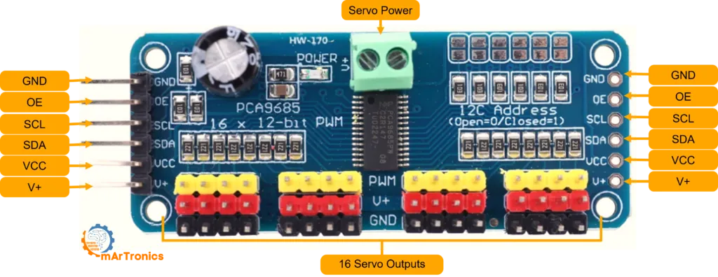
PCA9685 servo driver
Why not just use ESP32’s built-in PWM? Here’s the problem: the ESP32’s LEDC (LED controller) PWM is interrupt-driven. When WiFi interrupts fire (which happens constantly), the PWM duty cycle can jitter. That jitter gets transmitted to the servos, causing micro-oscillations. You see the gripper fingers twitch slightly.
The PCA9685 is a dedicated I2C servo driver that generates PWM on its own hardware. Once you set the pulse width, it holds it without any CPU involvement. WiFi can interrupt all it wants and the servo signal stays clean.
The PCA9685 costs $2 and Adafruit has a well-tested library for it. I2C only uses 2 wires (GPIO21 and GPIO22 on the ESP32), so the wiring stays simple.
Power supply sizing
The 5V 10A supply is sized for the worst-case power draw. We calculated 9960mA at absolute peak (all three heavy servos stalling simultaneously). In practice, you never do that. But if your power supply is undersized, even normal movement causes voltage sag, servos slow down, and the arm responds sluggishly.
A 5V 10A supply is the smallest I’d recommend. A 5V 15A supply is safer and only costs $3 more. The 5.5mm x 2.1mm barrel jack is the standard for this voltage range.
Fasteners and extras
The design uses a mix of metric and imperial fasteners. The No.2-32 and No.3-28 truss head screws (items 15, 16, 20, 24, 25) mount the servos into their brackets. The M3x16 hex socket screws (item 18) join structural parts together. The M3x6 cross-recess screws (item 22) attach servo horns to linkages. The M1.6×2 screws (item 17) secure the SG90 servos. Buy one assorted screw kit that covers all sizes — you’ll have spares.
Heat-set inserts are not necessary for this design. The STL files have screw holes sized so M3 screws thread directly into the plastic. PLA taps cleanly without pre-drilling. If you plan to disassemble the arm frequently, heat-set inserts make the threads more durable, but for a finished arm that stays assembled, screwing directly into the printed holes works fine.
The 686ZZ bearing is optional. You can let the servo horn rotate the plastic base directly, and it works fine. The bearing reduces friction and slop, making the base rotation smoother and more accurate. For $2, I consider it worth it. It’s a deep-groove ball bearing, 6mm ID (fits the servo shaft), 13mm OD (fits in the pocket I designed), 5mm wide.
The spring is a standard extension spring you can find in any hardware store spring assortment. Details on the spring specs and mounting are in the Shoulder Joint section above.
5. Assembly guide
This section walks through each step with the assumption you’ve already printed all 16 parts and you’re sitting at your workbench with a box of fasteners and servos.
Step 0: center every servo (do this FIRST)
Before you touch a single screw, center every servo to its 0-degree position. Skip this and you’ll spend hours troubleshooting why your arm moves to the wrong angles. I’m serious.
Servos ship with no knowledge of where they are mechanically. The servo horn could be at any angle relative to the internal servo mechanism. If you bolt a servo horn to an arm link while the servo thinks it’s at 0 degrees, but the horn is actually 45 degrees off, then when you command the servo to 0 degrees in your code, the arm won’t respond as expected.
The solution: use the serial firmware to center all servos. Power everything up, connect to the serial port at 115200 baud, and send the command:
HOME
This moves all servos to 0 degrees (the home position). While that’s happening, gently press each servo horn toward its “straight out” position. Some horns come pre-aligned, but some don’t. Once it’s aligned, hold it there. The servo will lock in place once it reaches 90 degrees. Now it’s centered. Repeat for all six servos.
Why does this matter? Because when you bolt things together, you’re committing to an angle. If a servo is off-center, every subsequent angle command will be wrong. You’ll spend hours troubleshooting.
Step 1: insert base servo (J1) into base_link
Start with base_link, the stationary bottom piece. Locate the rectangular servo pocket inside. Slide the first MG996R servo in from the top, motor shaft pointing upward. It should fit snugly. Secure it with the No.2-32 3/8″ truss head screws (item 15) through the servo mounting lugs. Don’t over-tighten — firm and snug is enough.
Step 2: install bearing
Press-fit the 686ZZ bearing (item 26) into the center hole of base_link. The bearing is a tight fit by design. If it doesn’t slide in, lightly sand the outer edge of the bearing with 120-grit sandpaper. It should pop in with firm hand pressure.
Step 3: attach servo horn to base_link_upper
Take base_link_upper (the rotating top piece). Bolt the cross-shaped MG955 servo horn (item 21) to the bottom side using an M3x6 cross-recess screw (item 22). Align the horn so it sits centered. This is what connects the upper base to the servo shaft.
Step 4: assemble base_link_upper onto base_link
Slide base_link_upper over the bearing and onto the centered servo shaft. The servo horn should engage with the servo splines. Test by hand: rotate it. It should spin smoothly without binding.
Step 5: mount shoulder servo (J2)
Insert the second MG996R servo into the shoulder bracket on base_link_upper. The output shaft points to the side (horizontal). Secure with No.2-32 3/8″ truss head screws (item 15).
Step 6: attach servo horn to arm_link_1 (upper arm)
Bolt the servo horn to arm_link_1. This is the connection between the shoulder servo and the upper arm. Align the horn so the arm points forward when the servo is at 90 degrees.
Step 7: install spring assist
Hook the extension spring (item 29) between base_link_upper and arm_link_1. Both parts have a small slot with a hook point on the inner side. Loop one end of the spring into the slot on base_link_upper, then stretch it slightly and loop the other end into the slot on arm_link_1. When the arm hangs down, the spring should be under tension and pulling the arm upward. This spring assist reduces the load on the shoulder servo by about 2 kgf·cm.
Step 8: mount elbow servo (J3)
Insert the third MG996R servo into the elbow bracket at the end of arm_link_1. Output shaft points to the side. Secure with No.2-32 3/8″ truss head screws (item 15).
Step 9: attach servo horn to arm_link_2 (forearm)
Bolt the servo horn to arm_link_2. Same approach as step 6 — align the horn so the forearm extends straight when the servo is at 90 degrees.
Step 10: connect arm_link_2 to arm_link_1
Slide arm_link_2 onto the elbow servo shaft. The horn engages with the splines. Secure with the center screw. Test: the forearm should swing freely through its full range.

Step 11: mount wrist pitch servo (J4)
Insert the first SG90 servo into the wrist bracket at the end of arm_link_2. The SG90 is much smaller than the MG996R. It clips into place.
Step 12: attach servo horn to arm_link_3 (wrist segment)
Bolt the SG90 horn to arm_link_3. This small horn connects the wrist pitch servo to the wrist segment.
Step 13: connect arm_link_3 to arm_link_2
Slide arm_link_3 onto the wrist pitch servo shaft. The wrist should tilt up and down freely.
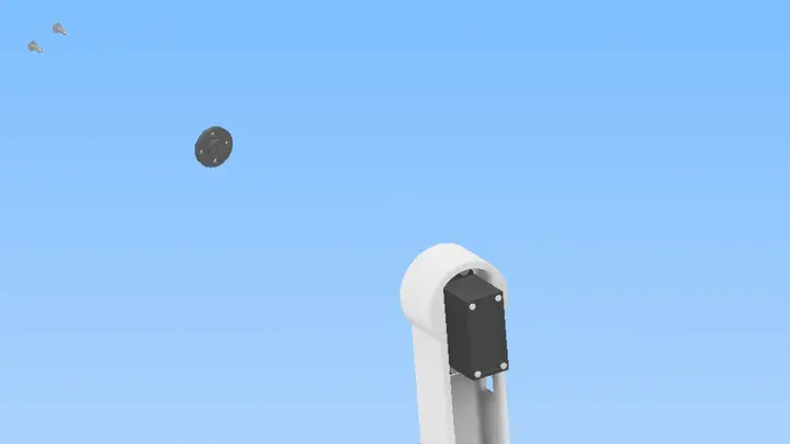
Step 14: mount wrist roll servo (J5)
Insert the second SG90 into the wrist roll bracket on arm_link_3. This servo sits perpendicular to J4.
Step 15: attach servo horn to gripper_base
Bolt the SG90 horn to gripper_base. This connects the wrist roll axis to the gripper housing.
Step 16: attach gripper_base to arm_link_3
Slide gripper_base onto the wrist roll servo shaft. The gripper should rotate freely around the roll axis.
Step 17: mount gripper servo (J6)
Insert the third SG90 into the gripper housing. This is the servo that opens and closes the jaws.
Step 18: attach servo horn to gripper gear
Bolt the servo horn to the left driving gear (Gear_links). This converts the servo rotation into jaw movement.
Step 19: install gripper gears into gripper_base
Mesh Gear_links and Gear_rechts into the gripper base. The teeth should just barely touch. Too tight and the servo can’t turn. Too loose and the gripper has slop.
Step 20: complete gripper assembly
Attach both gripper fingers (Gripper and Gripper_2) to the gear linkages. Test by hand: rotate the servo horn slowly. Both fingers should close symmetrically. Open fully, close fully, open again. No jamming.

Step 21: final check
The arm is fully assembled. Route all six servo wires back toward the base. Leave slack so the wires don’t pull when the arm moves. Use loose cable ties to bundle them.
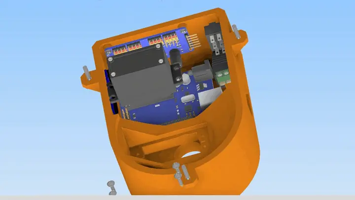
Mount the electronics board (ESP32 + PCA9685 on a breadboard) near the base. Connect all servo wires to the PCA9685 channels (see wiring table in Section 6). Connect ESP32 to PCA9685 via I2C (GPIO21 SDA, GPIO22 SCL). Connect the 5V power supply. Then plug in USB and load the firmware.
6. Wiring and electronics integration
The electrical system has three parts: power supply, servo driver, and microcontroller. Here’s how they connect:
System architecture
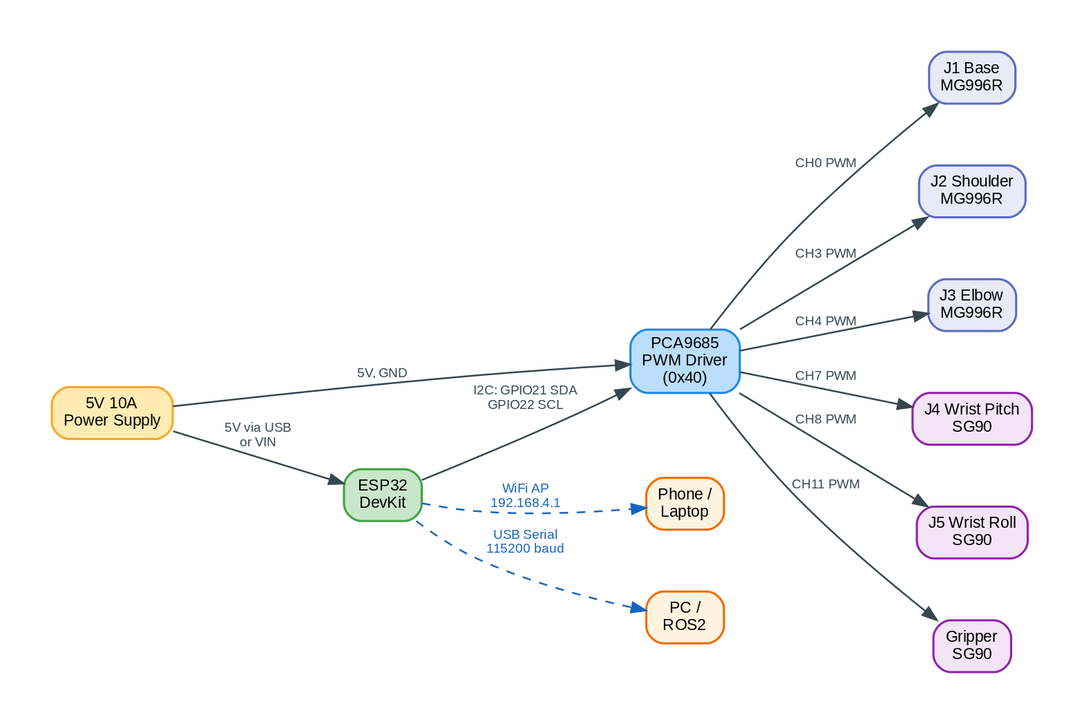
The ESP32 talks to the PCA9685 over I2C and to the outside world over WiFi or USB serial. The PCA9685 handles all servo PWM signals independently, so the ESP32’s WiFi interrupts don’t cause jitter. All servos draw power directly from the 5V supply through the PCA9685 board, not from the ESP32.
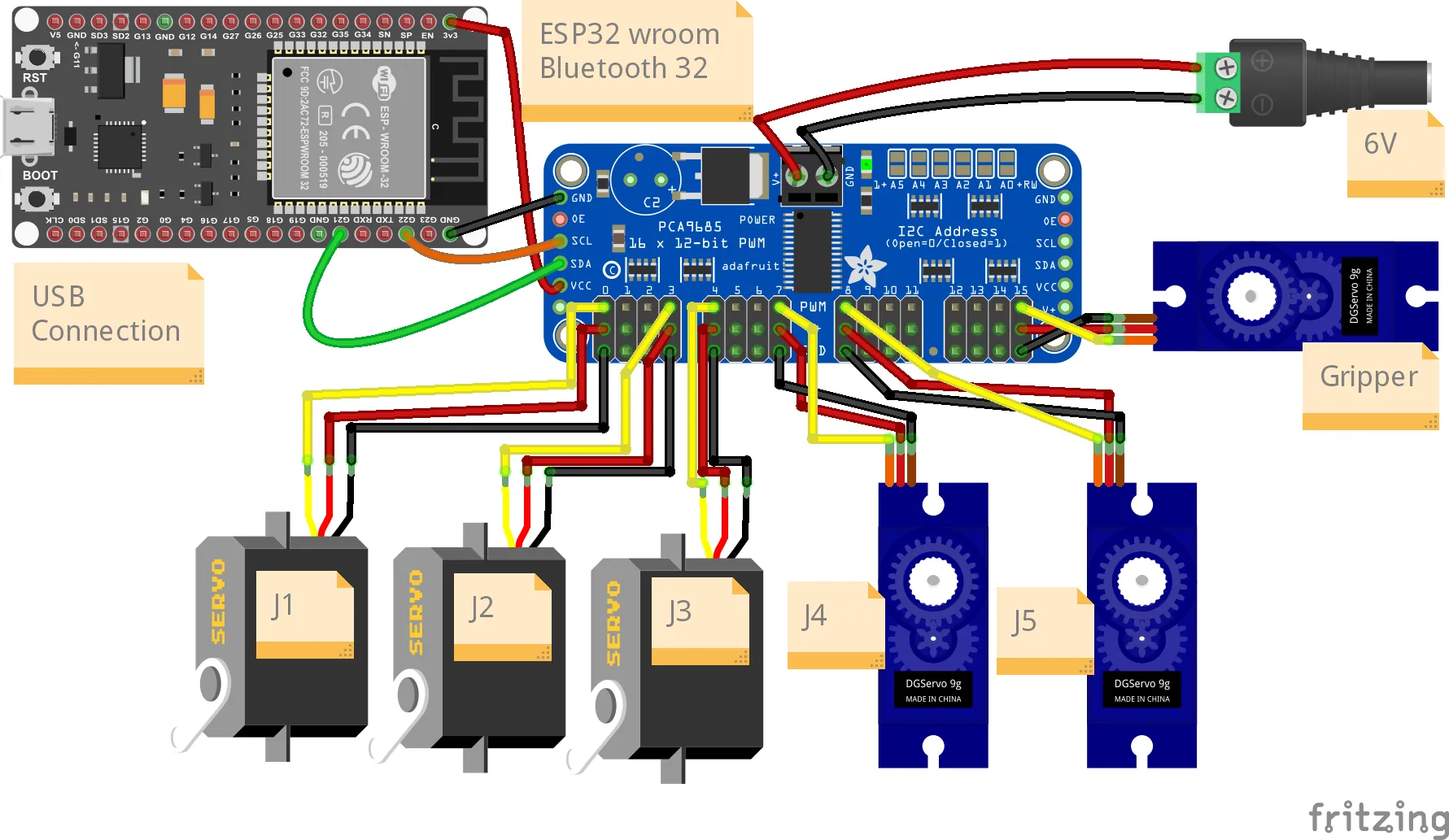
Wiring diagram
The connection list in detail:
Power: 5V 10A supply positive (red) to PCA9685 V+, negative (black) to PCA9685 GND. If you’re not powering the ESP32 over USB, run a wire from the same 5V rail to ESP32 VIN.
I2C bus: ESP32 GPIO21 (SDA) to PCA9685 SDA. ESP32 GPIO22 (SCL) to PCA9685 SCL. Connect all GND lines together (ESP32, PCA9685, power supply).
Servos to PCA9685 channels (each servo has three wires: V+, GND, signal):
| Servo | Joint | PCA9685 channel |
|---|---|---|
| MG996R | J1 Base | CH0 |
| MG996R | J2 Shoulder | CH3 |
| MG996R | J3 Elbow | CH4 |
| SG90 | J4 Wrist pitch | CH7 |
| SG90 | J5 Wrist roll | CH8 |
| SG90 | Gripper | CH11 |
Wire gauge and connections
Servo wires are usually 22AWG, which is fine for this low-current application. The PCA9685 can source up to 1A per channel, but in practice, the ESP32 can’t provide enough current via I2C to do that. We’re powering the servos directly from the 5V supply, which eliminates that constraint.
For the main 5V power distribution, I use 18AWG or 16AWG wire from the barrel jack to the breadboard 5V and GND rails. This is overkill but ensures no voltage drop.
The I2C wires from ESP32 to PCA9685 (GPIO21 and GPIO22) can be thin (22AWG) because I2C is low-current. Use separate wires, not twisted pairs, to reduce parasitic capacitance.
Common mistakes
Forget the common ground: This is the number-one killer. The ESP32, PCA9685, and power supply MUST share a common ground. Don’t have isolated ground planes. Every single GND signal must ultimately connect to the power supply’s negative terminal.
Power servos from the ESP32: Don’t do this. The ESP32’s 3.3V output can only source about 80mA. A single MG996R stall current is 2500mA. Even the 5V GPIO pins (which are really 3.3V) can only source about 500mA total. The servos will brown out the ESP32, and it will reset. Always use the external 5V supply for servo power.
Skip the I2C pull-up resistors: The PCA9685 has internal pull-ups on SDA and SCL, so technically you don’t need external ones for short wires. I’ve tested this and it works fine. If you get glitchy I2C, add 4.7K pull-ups from SDA and SCL to 3.3V.
Wrong I2C address: The PCA9685 defaults to address 0x40 (0x50 with hardware address pins). The code assumes 0x40. If you solder pins on your board, you might change the address by accident. Check the board. It should have three pins marked A0, A1, A2. If they’re not soldered, you’re at 0x40.
Servo power supply sag: If you’re running a long arm sequence and the voltage suddenly drops, it’s usually because the supply is at its limit. Either upgrade to a bigger supply or run movements more slowly (use the SPEED command).
7. Firmware: ESP32 serial control
The serial firmware is the foundation. It runs on the ESP32 and accepts text commands over USB serial. It’s the fastest way to test new joint angles without compiling a web interface.
Setup
You’ll need:
– Arduino IDE 2.x (or PlatformIO) installed
– ESP32 board package: go to File > Preferences, paste https://raw.githubusercontent.com/espressif/arduino-esp32/gh-pages/package_esp32_index.json into “Additional Board Manager URLs”, then open Tools > Board > Boards Manager, search “esp32”, and install “esp32 by Espressif Systems”
– Adafruit PWMServoDriver library: go to Sketch > Include Library > Manage Libraries, search “Adafruit PWM Servo Driver Library”, install it
– A USB-C (or micro-USB) cable to connect the ESP32 to your computer
Once installed, open Arduino IDE, select Tools > Board > ESP32 Dev Module (not “ESP32S2” or other variants), and select the correct COM port. Open the Serial Monitor (Ctrl+Shift+M) and set baud rate to 115200.
The firmware code
Here’s the complete OmArmZeroControl.ino:
#include <Wire.h>
#include <Adafruit_PWMServoDriver.h>
// Create servo driver object. Address 0x40 is the default
Adafruit_PWMServoDriver pwm = Adafruit_PWMServoDriver(0x40);
// Servo configuration
// Standard servo: 1000 us = 0 degrees, 2000 us = 180 degrees
// But we're using a wider range for these servos:
// MG996R: 500-2500 us (but safer to limit to 600-2400 us)
// SG90: 500-2400 us
// Define which servo is on which channel
const int SERVO_BASE = 0; // J1: MG996R
const int SERVO_SHOULDER = 3; // J2: MG996R
const int SERVO_ELBOW = 4; // J3: MG996R
const int SERVO_WRIST_PITCH = 7; // J4: SG90
const int SERVO_WRIST_ROLL = 8; // J5: SG90
const int SERVO_GRIPPER = 11; // Gripper: SG90
// Servo angle limits (degrees)
const int ANGLE_MIN = 0;
const int ANGLE_MAX = 180;
// Pulse width range for servos (in microseconds)
// MG996R on 5V is roughly 500-2500 us, but we'll be conservative
const int PULSE_MIN = 600; // 0 degrees (microseconds)
const int PULSE_MAX = 2400; // 180 degrees (microseconds)
// PCA9685 frequency is 50Hz for servos (20ms per cycle)
#define SERVO_FREQ 50
// Smooth movement parameters
int targetAngles[6] = {90, 90, 90, 90, 90, 90}; // Target angles for each servo
int currentAngles[6] = {90, 90, 90, 90, 90, 90}; // Current angles
int moveSpeed = 5; // Degrees per 20ms cycle (5 = 5 deg/20ms = 250 deg/s max)
int moveInterval = 20; // Milliseconds between updates
// Serial buffer
const int BUFFER_SIZE = 128;
char serialBuffer[BUFFER_SIZE];
int bufferIndex = 0;
// Timing for smooth motion
unsigned long lastMoveTime = 0;
void setup() {
Serial.begin(115200);
delay(1000);
Serial.println("OmArm Zero - 6-DOF (5+1 Gripper) Robotic Arm");
Serial.println("Initializing I2C and servo driver...");
Wire.begin(21, 22); // SDA=GPIO21, SCL=GPIO22
pwm.begin();
pwm.setOscillatorFrequency(27000000);
pwm.setPWMFreq(SERVO_FREQ);
Serial.println("PCA9685 initialized at 50Hz");
Serial.println("Sending all servos to home position (0 degrees)...");
// Move all servos to home
for (int i = 0; i < 6; i++) {
targetAngles[i] = 90;
currentAngles[i] = 90;
setServoAngle(i, 90);
}
delay(1000);
Serial.println("Ready. Send commands:");
Serial.println(" HOME - move all to 0 degrees");
Serial.println(" STATUS - print current positions");
Serial.println(" MOVE:d1,d2,d3,d4,d5,d6 - move to angles");
Serial.println(" 1,90 - move J1 to 90 degrees");
Serial.println(" SPEED:speed,interval - set move speed");
Serial.println();
lastMoveTime = millis();
}
void loop() {
// Handle serial input
if (Serial.available()) {
char c = Serial.read();
// Basic line buffering
if (c == '\n' || c == '\r') {
if (bufferIndex > 0) {
serialBuffer[bufferIndex] = '\0';
processCommand(serialBuffer);
bufferIndex = 0;
}
} else if (bufferIndex < BUFFER_SIZE - 1) {
serialBuffer[bufferIndex++] = c;
}
}
// Update servo positions smoothly
updateServoMovement();
}
void processCommand(const char* cmd) {
String input(cmd);
input.trim();
input.toUpperCase();
if (input == "HOME") {
// Move all servos to home position
for (int i = 0; i < 6; i++) {
targetAngles[i] = 90;
}
Serial.println("HOME command: moving all servos to 0 degrees");
} else if (input.startsWith("STATUS")) {
// Print current angles
Serial.print("Current angles: ");
for (int i = 0; i < 6; i++) {
Serial.print("J");
Serial.print(i + 1);
Serial.print("=");
Serial.print(currentAngles[i]);
if (i < 5) Serial.print(", ");
}
Serial.println();
} else if (input.startsWith("MOVE:")) {
// Parse MOVE:d1,d2,d3,d4,d5,d6
String params = input.substring(5);
parseAngles(params);
Serial.print("Moving to: ");
for (int i = 0; i < 6; i++) {
Serial.print(targetAngles[i]);
if (i < 5) Serial.print(", ");
}
Serial.println();
} else if (input.startsWith("SPEED:")) {
// Parse SPEED:speed,interval
String params = input.substring(6);
int commaIndex = params.indexOf(',');
if (commaIndex > 0) {
moveSpeed = params.substring(0, commaIndex).toInt();
moveInterval = params.substring(commaIndex + 1).toInt();
Serial.print("Speed set to ");
Serial.print(moveSpeed);
Serial.print(" deg/");
Serial.print(moveInterval);
Serial.println(" ms");
}
} else if (input.indexOf(',') > 0) {
// Single joint command: J,angle
int commaIndex = input.indexOf(',');
int jointNum = input.substring(0, commaIndex).toInt() - 1; // Convert 1-based to 0-based
int angle = input.substring(commaIndex + 1).toInt();
if (jointNum >= 0 && jointNum < 6 && angle >= ANGLE_MIN && angle <= ANGLE_MAX) {
targetAngles[jointNum] = angle;
Serial.print("J");
Serial.print(jointNum + 1);
Serial.print(" -> ");
Serial.println(angle);
} else {
Serial.println("Invalid joint or angle");
}
} else {
Serial.println("Unknown command");
}
}
void parseAngles(const String& params) {
// Parse comma-separated angles
int angles[6];
int angleCount = 0;
int lastComma = -1;
for (int i = 0; i <= params.length(); i++) {
if (params[i] == ',' || i == params.length()) {
if (i > lastComma + 1 && angleCount < 6) {
String numStr = params.substring(lastComma + 1, i);
angles[angleCount] = numStr.toInt();
angleCount++;
}
lastComma = i;
}
}
// Apply parsed angles
for (int i = 0; i < angleCount && i < 6; i++) {
if (angles[i] >= ANGLE_MIN && angles[i] <= ANGLE_MAX) {
targetAngles[i] = angles[i];
}
}
}
void updateServoMovement() {
unsigned long now = millis();
// Check if it's time to update servo positions
if (now - lastMoveTime >= moveInterval) {
lastMoveTime = now;
// Move each servo toward its target
for (int i = 0; i < 6; i++) {
if (currentAngles[i] != targetAngles[i]) {
int diff = targetAngles[i] - currentAngles[i];
// Move by up to moveSpeed degrees per interval
if (abs(diff) <= moveSpeed) {
currentAngles[i] = targetAngles[i];
} else if (diff > 0) {
currentAngles[i] += moveSpeed;
} else {
currentAngles[i] -= moveSpeed;
}
// Send new angle to servo
setServoAngle(i, currentAngles[i]);
}
}
}
}
void setServoAngle(int servoIndex, int angle) {
// Clamp angle to valid range
if (angle < ANGLE_MIN) angle = ANGLE_MIN;
if (angle > ANGLE_MAX) angle = ANGLE_MAX;
// Convert angle (0-180) to pulse width (PULSE_MIN to PULSE_MAX)
int pulseWidth = map(angle, 0, 180, PULSE_MIN, PULSE_MAX);
// Convert pulse width (microseconds) to PCA9685 tick count.
// The PCA9685 divides one 20ms cycle into 4096 ticks.
// So we map from the full 20000us period to the 0-4096 range.
// Example: 1500us (90°) — map(1500, 0, 20000, 0, 4096) = 307 ticks.
int pwmValue = map(pulseWidth, 0, 20000, 0, 4096);
// Get the channel for this servo
int channel = getChannelForServo(servoIndex);
// Set the PWM pulse
pwm.setPWM(channel, 0, pwmValue);
}
int getChannelForServo(int servoIndex) {
// Map servo index to channel
const int channels[6] = {
SERVO_BASE, // Index 0 -> J1
SERVO_SHOULDER, // Index 1 -> J2
SERVO_ELBOW, // Index 2 -> J3
SERVO_WRIST_PITCH, // Index 3 -> J4
SERVO_WRIST_ROLL, // Index 4 -> J5
SERVO_GRIPPER // Index 5 -> Gripper
};
return channels[servoIndex];
}
Code walkthrough
Libraries and I2C setup: The Wire library handles I2C communication. Adafruit_PWMServoDriver is the library for the PCA9685. In setup(), we initialize Wire with GPIO21 (SDA) and GPIO22 (SCL), then initialize the PWM driver at 50Hz.
Servo channels: The array SERVO_BASE, SERVO_SHOULDER, etc. maps the logical servos (J1-J5 and gripper) to physical PCA9685 channels. You might wonder why CH0, CH3, CH4, CH7, CH8, CH11 instead of sequential 0-5. The reason is physical: each servo has a 3-pin connector, and on the PCA9685 breakout board the channels are laid out in a row. By spacing the channels, I keep the servo wires from bunching up on one side of the board. If your wiring layout is different, just change the channel numbers in the code. The mapping is in one place (getChannelForServo()), so a single edit fixes everything.
Pulse width conversion: Servos respond to PWM signals. The pulse width determines the angle. For a standard servo, 1500 microseconds is the middle position (90 degrees). We use 600us for 0 degrees and 2400us for 180 degrees. The PCA9685 works in its own units (0-4095 for a 20ms cycle), so we map servo pulse widths to PCA9685 units in the setServoAngle() function.
Smooth movement: The updateServoMovement() function runs in the main loop. Each iteration, it compares the current angle to the target angle and increments (or decrements) by moveSpeed degrees. This creates smooth acceleration. The moveInterval controls how often updates happen. At 20ms interval and 5 degrees per interval, you get smooth motion at about 250 degrees per second.
Serial protocol: The processCommand() function parses incoming serial commands. The HOME command moves all servos to 0 degrees. MOVE:angle1,angle2,… sets target angles for all six servos. Single-joint commands like “1,45” move just J1 to 45 degrees. SPEED:speed,interval adjusts the movement speed.
Safety: Each command validates angle ranges (0-180) and joint numbers (1-6) before executing. If someone sends an invalid angle, it’s silently clamped to the valid range. Invalid joint numbers are rejected.
Firmware control flow
The main loop does two things on every iteration: check for serial input, and update servo positions. Here’s the flow:
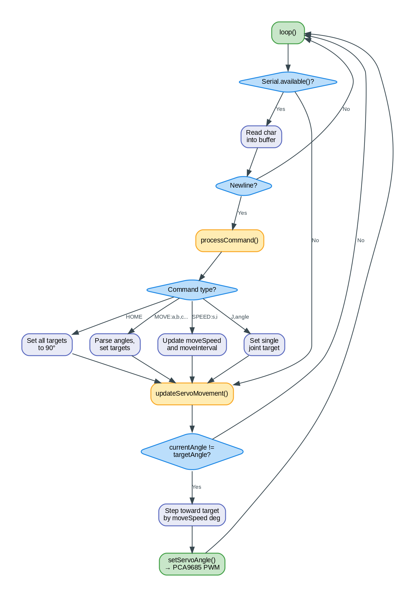
The key thing to notice: the servo update runs on every loop iteration, not only when a command arrives. That’s what makes the movement smooth. The command just sets a new target. The loop does the interpolation.
Testing the serial firmware
Before uploading the servo code, verify that your I2C wiring works. Upload a simple I2C scanner sketch first:
#include <Wire.h>
void setup() {
  Serial.begin(115200);
  Wire.begin(21, 22);
  Serial.println("Scanning I2C bus...");
  for (byte addr = 1; addr < 127; addr++) {
    Wire.beginTransmission(addr);
    if (Wire.endTransmission() == 0) {
      Serial.print("Found device at 0x");
      Serial.println(addr, HEX);
    }
  }
  Serial.println("Done.");
}
void loop() {}
You should see Found device at 0x40. If nothing shows up, check SDA/SCL wiring. If you see a different address (like 0x41), your PCA9685 has an address pin soldered, and you’ll need to update the address in the servo code.
Once I2C is confirmed, upload the OmArmZeroControl sketch. Open the Serial Monitor (Ctrl+Shift+M) at 115200 baud. You should see the startup message.
Try these commands:
HOME
All servos should move to 90 degrees. If a servo doesn’t move, check its wiring.
1,0
J1 (the base) should rotate fully counterclockwise.
1,180
J1 should rotate fully clockwise.
MOVE:90,45,135,90,90,90
J2 moves to 45 degrees (arm lifts), J3 moves to 135 degrees (elbow bends), others stay at 90.
STATUS
Prints the current angle of each joint.
SPEED:2,50
Sets move speed to 2 degrees per 50ms update, which is slower.
If a servo doesn’t respond, check:
1. Is it powered? (Check the servo doesn’t twitch when you send a command.)
2. Is the channel correct? (Edit the channel mapping and retry.)
3. Is the I2C communication working? (Check that the PCA9685 is recognized. Add debug print statements.)
4. Is the servo damaged? (Try another servo in that channel.)
Once the serial control is working reliably, you’re ready for the web GUI.
8. Web-based GUI
The serial firmware is great for testing, but controlling a robotic arm with text commands gets old fast. The web GUI lets you point your phone at the arm, visit a web page, and drag sliders to move joints in real-time.
The OmArmZero_LittleFS firmware runs the ESP32 as a WiFi access point. It serves a web interface directly from the ESP32’s flash memory (LittleFS). No router required. No internet required. Just turn on the arm, connect to its WiFi network, and open 10.10.10.1 in your browser.
Architecture
The ESP32 runs three things concurrently:
1. A WiFi access point named “OmArmZero”
2. An HTTP web server on port 80
3. The same servo control logic as the serial firmware
The web interface is a single-page app (SPA) written in HTML, CSS, and JavaScript. The HTML and assets are stored in LittleFS, a flash filesystem on the ESP32. When you visit 10.10.10.1, the server serves the HTML. The JavaScript in that HTML contacts the ESP32’s API endpoint to send commands and receive status.
Here’s what happens when you drag a slider:
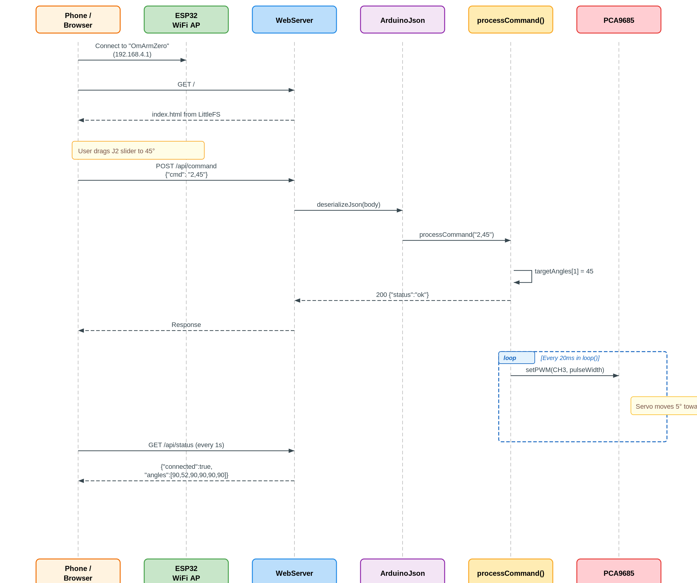
The browser sends a POST with JSON, the firmware parses it and sets a target angle, and the same smooth-movement loop from the serial firmware does the actual interpolation. The status endpoint lets the browser poll for current joint positions every second.
Why LittleFS instead of hardcoding HTML as a string? Because it’s cleaner to maintain, you can include images, and it separates the firmware logic from the web assets.
Setting up the web interface
You’ll need the LittleFS upload tool for Arduino IDE. The tool is ESP32-specific and is maintained separately from Adafruit’s libraries. For Arduino IDE 1.x, download the arduino-esp32fs-plugin by lorol. For Arduino IDE 2.x, use the LittleFS upload plugin for IDE 2.x. The steps:
- Download the .vsix (IDE 2.x) or .jar (IDE 1.x) file from the release page.
- For IDE 1.x: place the .jar in your
Arduino/tools/ESP32FS/tool/folder (create it if needed). For IDE 2.x: install the .vsix through the Extensions panel. - Restart Arduino IDE.
- You’ll see “Tools > ESP32 Sketch Data Upload” (IDE 1.x) or a command palette option (IDE 2.x).
Before you upload, create a folder called “data” in the same directory as the sketch file. Inside, place:
– index.html
– style.css
– app.js
– Any image files (optional)
Then select the upload option. Arduino will pack everything in the data folder into a LittleFS image and flash it to the ESP32.
Troubleshooting the LittleFS upload (this is where most people get stuck):
If the upload fails with “Wrong board” or hangs at “Connecting…”: make sure you selected “ESP32 Dev Module” as the board, not a generic ESP32. Also check that the correct COM port is selected and that the Serial Monitor is closed (it locks the port).
If the upload succeeds but the web page shows “index.html not found”: the partition scheme is wrong. Go to Tools > Partition Scheme and select “Default 4MB with spiffs (1.2MB APP/1.5MB SPIFFS)”. Despite the name saying “SPIFFS”, this partition scheme allocates 1.5MB of flash storage that LittleFS uses for your web files. LittleFS replaced SPIFFS as the recommended filesystem, but the partition label was never renamed in the Arduino IDE. Reupload after changing this.
If the data folder is not being found: it must be named exactly “data” (lowercase) and it must sit in the same folder as the .ino file. Not one level up, not inside a subfolder. Same folder.
Web interface files
Here are the core files:
index.html:
<!DOCTYPE html>
<html lang="en">
<head>
  <meta charset="UTF-8">
  <meta name="viewport" content="width=device-width, initial-scale=1.0">
  <title>OmArm Zero Control</title>
  <link rel="stylesheet" href="style.css">
</head>
<body>
  <div class="container">
    <header>
      <h1>OmArm Zero</h1>
      <div id="status" class="status disconnected">Disconnected</div>
    </header>

    <main>
      <section class="control-panel">
        <h2>Joint Control</h2>
        <div class="joint-group">
          <label for="j1">J1 Base (0-180°)</label>
          <input type="range" id="j1" min="0" max="180" value="90" class="slider">
          <span id="j1-value">90</span>°
        </div>

        <div class="joint-group">
          <label for="j2">J2 Shoulder (0-180°)</label>
          <input type="range" id="j2" min="0" max="180" value="90" class="slider">
          <span id="j2-value">90</span>°
        </div>

        <div class="joint-group">
          <label for="j3">J3 Elbow (0-180°)</label>
          <input type="range" id="j3" min="0" max="180" value="90" class="slider">
          <span id="j3-value">90</span>°
        </div>

        <div class="joint-group">
          <label for="j4">J4 Wrist Pitch (0-180°)</label>
          <input type="range" id="j4" min="0" max="180" value="90" class="slider">
          <span id="j4-value">90</span>°
        </div>

        <div class="joint-group">
          <label for="j5">J5 Wrist Roll (0-180°)</label>
          <input type="range" id="j5" min="0" max="180" value="90" class="slider">
          <span id="j5-value">90</span>°
        </div>

        <div class="joint-group">
          <label for="gripper">Gripper (0-180°)</label>
          <input type="range" id="gripper" min="0" max="180" value="90" class="slider">
          <span id="gripper-value">90</span>°
        </div>
      </section>

      <section class="settings">
        <h2>Settings</h2>
        <div class="setting-group">
          <label for="speed">Movement Speed (deg/update)</label>
          <input type="number" id="speed" min="1" max="20" value="5">
        </div>

        <button id="homeButton" class="button primary">Home Position</button>
      </section>

      <section class="sequences">
        <h2>Sequences</h2>
        <button id="recordButton" class="button">Record Sequence</button>
        <button id="playButton" class="button" disabled>Play Sequence</button>
        <button id="clearButton" class="button">Clear Sequence</button>
        <textarea id="sequenceJSON" placeholder="Recorded sequence will appear here"></textarea>
        <input type="file" id="loadSequence" accept=".json" style="display:none">
        <button id="loadButton" class="button">Load Sequence</button>
      </section>
    </main>

    <footer>
      <p>OmArm Zero v1.0 - 6-DOF (5+1 Gripper) Robotic Arm</p>
    </footer>
  </div>

  <script src="app.js"></script>
</body>
</html>
style.css:
* {
  margin: 0;
  padding: 0;
  box-sizing: border-box;
}

body {
  font-family: -apple-system, BlinkMacSystemFont, "Segoe UI", Roboto, Oxygen, Ubuntu, sans-serif;
  background: linear-gradient(135deg, #667eea 0%, #764ba2 100%);
  min-height: 100vh;
  padding: 10px;
}

.container {
  max-width: 600px;
  margin: 0 auto;
  background: white;
  border-radius: 12px;
  box-shadow: 0 20px 60px rgba(0, 0, 0, 0.3);
  overflow: hidden;
  display: flex;
  flex-direction: column;
  min-height: 100vh;
}

header {
  background: linear-gradient(135deg, #667eea 0%, #764ba2 100%);
  color: white;
  padding: 20px;
  text-align: center;
}

header h1 {
  font-size: 28px;
  margin-bottom: 10px;
}

.status {
  display: inline-block;
  padding: 6px 12px;
  border-radius: 20px;
  font-size: 12px;
  font-weight: bold;
}

.status.connected {
  background: #4caf50;
  color: white;
}

.status.disconnected {
  background: #f44336;
  color: white;
}

main {
  flex: 1;
  padding: 20px;
  overflow-y: auto;
}

section {
  margin-bottom: 30px;
  padding-bottom: 20px;
  border-bottom: 1px solid #eee;
}

section:last-child {
  border-bottom: none;
}

section h2 {
  font-size: 18px;
  margin-bottom: 15px;
  color: #333;
}

.joint-group {
  display: flex;
  align-items: center;
  margin-bottom: 15px;
  gap: 10px;
}

.joint-group label {
  flex: 0 0 150px;
  font-size: 14px;
  color: #555;
}

.joint-group input[type="range"] {
  flex: 1;
  height: 6px;
  border-radius: 3px;
  background: #ddd;
  outline: none;
  -webkit-appearance: none;
  appearance: none;
}

.joint-group input[type="range"]::-webkit-slider-thumb {
  -webkit-appearance: none;
  appearance: none;
  width: 18px;
  height: 18px;
  border-radius: 50%;
  background: #667eea;
  cursor: pointer;
  box-shadow: 0 2px 4px rgba(0, 0, 0, 0.2);
}

.joint-group input[type="range"]::-moz-range-thumb {
  width: 18px;
  height: 18px;
  border-radius: 50%;
  background: #667eea;
  cursor: pointer;
  border: none;
  box-shadow: 0 2px 4px rgba(0, 0, 0, 0.2);
}

.joint-group span {
  flex: 0 0 40px;
  text-align: right;
  font-weight: bold;
  color: #333;
}

.setting-group {
  margin-bottom: 15px;
}

.setting-group label {
  display: block;
  font-size: 14px;
  margin-bottom: 5px;
  color: #555;
}

.setting-group input[type="number"] {
  width: 100%;
  padding: 8px;
  border: 1px solid #ddd;
  border-radius: 4px;
  font-size: 14px;
}

.button {
  display: inline-block;
  padding: 10px 20px;
  border: none;
  border-radius: 4px;
  font-size: 14px;
  cursor: pointer;
  transition: all 0.3s ease;
  background: #f0f0f0;
  color: #333;
  margin-right: 10px;
  margin-bottom: 10px;
}

.button:hover {
  background: #e0e0e0;
}

.button.primary {
  background: #667eea;
  color: white;
}

.button.primary:hover {
  background: #5568d3;
}

.button:disabled {
  opacity: 0.5;
  cursor: not-allowed;
}

#sequenceJSON {
  width: 100%;
  height: 120px;
  padding: 10px;
  border: 1px solid #ddd;
  border-radius: 4px;
  font-family: monospace;
  font-size: 12px;
  resize: vertical;
  margin: 10px 0;
}

footer {
  background: #f5f5f5;
  color: #999;
  text-align: center;
  padding: 15px;
  font-size: 12px;
  border-top: 1px solid #eee;
}

@media (max-width: 600px) {
  header h1 {
    font-size: 22px;
  }

  main {
    padding: 15px;
  }

  .joint-group label {
    flex: 0 0 120px;
  }
}
app.js:
// OmArm Zero Control Web App

const API_BASE = "/api";
const STATUS_CHECK_INTERVAL = 1000;

const sliders = {
  j1: document.getElementById("j1"),
  j2: document.getElementById("j2"),
  j3: document.getElementById("j3"),
  j4: document.getElementById("j4"),
  j5: document.getElementById("j5"),
  gripper: document.getElementById("gripper")
};

const sliderValues = {
  j1: document.getElementById("j1-value"),
  j2: document.getElementById("j2-value"),
  j3: document.getElementById("j3-value"),
  j4: document.getElementById("j4-value"),
  j5: document.getElementById("j5-value"),
  gripper: document.getElementById("gripper-value")
};

const statusDisplay = document.getElementById("status");
const speedInput = document.getElementById("speed");
const homeButton = document.getElementById("homeButton");
const recordButton = document.getElementById("recordButton");
const playButton = document.getElementById("playButton");
const clearButton = document.getElementById("clearButton");
const loadButton = document.getElementById("loadButton");
const sequenceJSON = document.getElementById("sequenceJSON");
const loadSequenceInput = document.getElementById("loadSequence");

let isConnected = false;
let isRecording = false;
let recordedSequence = [];

// Initialize
document.addEventListener("DOMContentLoaded", () => {
  // Slider listeners
  for (const [id, slider] of Object.entries(sliders)) {
    slider.addEventListener("input", (e) => {
      const angle = e.target.value;
      sliderValues[id].textContent = angle;
      sendCommand(id, angle);
    });
  }

  // Button listeners
  homeButton.addEventListener("click", () => {
    sendCommand("HOME", null);
    // Reset sliders to home position
    for (const slider of Object.values(sliders)) {
      slider.value = 90;
    }
    for (const value of Object.values(sliderValues)) {
      value.textContent = 90;
    }
  });

  recordButton.addEventListener("click", () => {
    if (!isRecording) {
      recordedSequence = [];
      isRecording = true;
      recordButton.textContent = "Stop Recording";
      recordButton.classList.add("recording");
    } else {
      isRecording = false;
      recordButton.textContent = "Record Sequence";
      recordButton.classList.remove("recording");
      saveSequenceToJSON();
    }
  });

  playButton.addEventListener("click", () => {
    playRecordedSequence();
  });

  clearButton.addEventListener("click", () => {
    recordedSequence = [];
    sequenceJSON.value = "";
    playButton.disabled = true;
  });

  loadButton.addEventListener("click", () => {
    loadSequenceInput.click();
  });

  loadSequenceInput.addEventListener("change", (e) => {
    const file = e.target.files[0];
    if (file) {
      const reader = new FileReader();
      reader.onload = (event) => {
        try {
          recordedSequence = JSON.parse(event.target.result);
          saveSequenceToJSON();
          playButton.disabled = false;
          alert("Sequence loaded successfully");
        } catch (err) {
          alert("Failed to parse sequence file: " + err.message);
        }
      };
      reader.readAsText(file);
    }
  });

  speedInput.addEventListener("change", () => {
    sendCommand("SPEED", speedInput.value);
  });

  // Check connection status periodically
  checkConnection();
  setInterval(checkConnection, STATUS_CHECK_INTERVAL);
});

function sendCommand(cmd, value) {
  let fullCmd = cmd;

  if (cmd === "HOME") {
    fullCmd = "HOME";
  } else if (cmd === "SPEED") {
    fullCmd = "SPEED:" + value + ",20";
  } else if (["j1", "j2", "j3", "j4", "j5", "gripper"].includes(cmd)) {
    // Single joint command
    const jointNum = cmd === "gripper" ? 6 : parseInt(cmd.slice(1));
    fullCmd = jointNum + "," + value;

    // Record if recording
    if (isRecording) {
      recordedSequence.push({
        j1: sliders.j1.value,
        j2: sliders.j2.value,
        j3: sliders.j3.value,
        j4: sliders.j4.value,
        j5: sliders.j5.value,
        gripper: sliders.gripper.value,
        timestamp: Date.now()
      });
    }
  }

  fetch(API_BASE + "/command", {
    method: "POST",
    headers: { "Content-Type": "application/json" },
    body: JSON.stringify({ cmd: fullCmd })
  }).catch(err => console.log("Command send error:", err));
}

function checkConnection() {
  fetch(API_BASE + "/status")
    .then(response => response.json())
    .then(data => {
      isConnected = true;
      statusDisplay.textContent = "Connected";
      statusDisplay.classList.remove("disconnected");
      statusDisplay.classList.add("connected");
    })
    .catch(err => {
      isConnected = false;
      statusDisplay.textContent = "Disconnected";
      statusDisplay.classList.remove("connected");
      statusDisplay.classList.add("disconnected");
    });
}

function saveSequenceToJSON() {
  sequenceJSON.value = JSON.stringify(recordedSequence, null, 2);
  playButton.disabled = recordedSequence.length === 0;
}

function playRecordedSequence() {
  if (recordedSequence.length === 0) return;

  playButton.disabled = true;
  let index = 0;

  const playStep = () => {
    if (index >= recordedSequence.length) {
      playButton.disabled = false;
      return;
    }

    const step = recordedSequence[index];
    const delay = index > 0 ? recordedSequence[index].timestamp - recordedSequence[index - 1].timestamp : 0;

    setTimeout(() => {
      for (const joint of ["j1", "j2", "j3", "j4", "j5", "gripper"]) {
        sliders[joint].value = step[joint];
        sliderValues[joint].textContent = step[joint];
        sendCommand(joint, step[joint]);
      }
      index++;
      playStep();
    }, Math.max(delay, 100));
  };

  playStep();
}
Firmware for web control
The OmArmZero_LittleFS.ino firmware is similar to the serial version, but adds WiFi and HTTP server:
#include <Wire.h>
#include <Adafruit_PWMServoDriver.h>
#include <WiFi.h>
#include <WebServer.h>
#include <LittleFS.h>
#include <ArduinoJson.h>

Adafruit_PWMServoDriver pwm = Adafruit_PWMServoDriver(0x40);
WebServer server(80);

// WiFi AP credentials
const char* SSID = "OmArmZero";
const char* PASSWORD = "omarmcontrol";

// Same servo configuration as serial version
const int SERVO_BASE = 0;
const int SERVO_SHOULDER = 3;
const int SERVO_ELBOW = 4;
const int SERVO_WRIST_PITCH = 7;
const int SERVO_WRIST_ROLL = 8;
const int SERVO_GRIPPER = 11;

const int ANGLE_MIN = 0;
const int ANGLE_MAX = 180;
const int PULSE_MIN = 600;
const int PULSE_MAX = 2400;
#define SERVO_FREQ 50

int targetAngles[6] = {90, 90, 90, 90, 90, 90};
int currentAngles[6] = {90, 90, 90, 90, 90, 90};
int moveSpeed = 5;
int moveInterval = 20;

unsigned long lastMoveTime = 0;

void setup() {
  Serial.begin(115200);
  delay(1000);

  Serial.println("OmArm Zero - Web Control Interface");

  // Initialize LittleFS
  if (!LittleFS.begin()) {
    Serial.println("LittleFS mount failed");
    return;
  }
  Serial.println("LittleFS mounted");

  // Initialize I2C and servo driver
  Wire.begin(21, 22);
  pwm.begin();
  pwm.setOscillatorFrequency(27000000);
  pwm.setPWMFreq(SERVO_FREQ);

  // Move all to home
  for (int i = 0; i < 6; i++) {
    setServoAngle(i, 90);
  }

  // Start WiFi AP
  WiFi.mode(WIFI_AP);
  WiFi.softAP(SSID, PASSWORD);
  IPAddress IP = WiFi.softAPIP();
  Serial.print("AP IP address: ");
  Serial.println(IP);

  // Set up web server routes
  server.on("/", handleRoot);
  server.on("/api/command", HTTP_POST, handleCommand);
  server.on("/api/status", HTTP_GET, handleStatus);
  server.onNotFound(handleNotFound);

  server.begin();
  Serial.println("Web server started");

  lastMoveTime = millis();
}

void loop() {
  server.handleClient();
  updateServoMovement();
}

void handleRoot() {
  if (LittleFS.exists("/index.html")) {
    File file = LittleFS.open("/index.html", "r");
    server.streamFile(file, "text/html");
    file.close();
  } else {
    server.send(404, "text/plain", "index.html not found");
  }
}

void handleCommand() {
  if (server.hasArg("plain")) {
    String body = server.arg("plain");

    StaticJsonDocument<256> doc;
    DeserializationError error = deserializeJson(doc, body);

    if (!error) {
      String cmd = doc["cmd"];
      processCommand(cmd.c_str());
      server.send(200, "application/json", "{\"status\":\"ok\"}");
    } else {
      server.send(400, "application/json", "{\"error\":\"JSON parse error\"}");
    }
  } else {
    server.send(400, "application/json", "{\"error\":\"No command\"}");
  }
}

void handleStatus() {
  StaticJsonDocument<256> doc;
  doc["connected"] = true;
  doc["angles"][0] = currentAngles[0];
  doc["angles"][1] = currentAngles[1];
  doc["angles"][2] = currentAngles[2];
  doc["angles"][3] = currentAngles[3];
  doc["angles"][4] = currentAngles[4];
  doc["angles"][5] = currentAngles[5];

  String response;
  serializeJson(doc, response);
  server.send(200, "application/json", response);
}

void handleNotFound() {
  // Try to serve the requested file from LittleFS
  String path = server.uri();
  if (path.endsWith("/")) {
    path += "index.html";
  }

  if (LittleFS.exists(path)) {
    File file = LittleFS.open(path, "r");
    String contentType = "application/octet-stream";
    if (path.endsWith(".html")) contentType = "text/html";
    else if (path.endsWith(".css")) contentType = "text/css";
    else if (path.endsWith(".js")) contentType = "application/javascript";
    else if (path.endsWith(".png")) contentType = "image/png";
    else if (path.endsWith(".jpg")) contentType = "image/jpeg";

    server.streamFile(file, contentType);
    file.close();
  } else {
    server.send(404, "text/plain", "File not found");
  }
}

void processCommand(const char* cmd) {
  String input(cmd);
  input.trim();
  input.toUpperCase();

  if (input == "HOME") {
    for (int i = 0; i < 6; i++) {
      targetAngles[i] = 90;
    }
  } else if (input.startsWith("MOVE:")) {
    String params = input.substring(5);
    parseAngles(params);
  } else if (input.startsWith("SPEED:")) {
    String params = input.substring(6);
    int commaIndex = params.indexOf(',');
    if (commaIndex > 0) {
      moveSpeed = params.substring(0, commaIndex).toInt();
      moveInterval = params.substring(commaIndex + 1).toInt();
    }
  } else if (input.indexOf(',') > 0) {
    int commaIndex = input.indexOf(',');
    int jointNum = input.substring(0, commaIndex).toInt() - 1;
    int angle = input.substring(commaIndex + 1).toInt();

    if (jointNum >= 0 && jointNum < 6 && angle >= ANGLE_MIN && angle <= ANGLE_MAX) {
      targetAngles[jointNum] = angle;
    }
  }
}

void parseAngles(const String& params) {
  int angles[6];
  int angleCount = 0;
  int lastComma = -1;

  for (int i = 0; i <= params.length(); i++) {
    if (params[i] == ',' || i == params.length()) {
      if (i > lastComma + 1 && angleCount < 6) {
        String numStr = params.substring(lastComma + 1, i);
        angles[angleCount] = numStr.toInt();
        angleCount++;
      }
      lastComma = i;
    }
  }

  for (int i = 0; i < angleCount && i < 6; i++) {
    if (angles[i] >= ANGLE_MIN && angles[i] <= ANGLE_MAX) {
      targetAngles[i] = angles[i];
    }
  }
}

void updateServoMovement() {
  unsigned long now = millis();

  if (now - lastMoveTime >= moveInterval) {
    lastMoveTime = now;

    for (int i = 0; i < 6; i++) {
      if (currentAngles[i] != targetAngles[i]) {
        int diff = targetAngles[i] - currentAngles[i];

        if (abs(diff) <= moveSpeed) {
          currentAngles[i] = targetAngles[i];
        } else if (diff > 0) {
          currentAngles[i] += moveSpeed;
        } else {
          currentAngles[i] -= moveSpeed;
        }

        setServoAngle(i, currentAngles[i]);
      }
    }
  }
}

void setServoAngle(int servoIndex, int angle) {
  if (angle < ANGLE_MIN) angle = ANGLE_MIN;
  if (angle > ANGLE_MAX) angle = ANGLE_MAX;

  int pulseWidth = map(angle, 0, 180, PULSE_MIN, PULSE_MAX);
  int pwmValue = map(pulseWidth, 0, 20000, 0, 4096);
  int channel = getChannelForServo(servoIndex);

  pwm.setPWM(channel, 0, pwmValue);
}

int getChannelForServo(int servoIndex) {
  const int channels[6] = {
    SERVO_BASE,
    SERVO_SHOULDER,
    SERVO_ELBOW,
    SERVO_WRIST_PITCH,
    SERVO_WRIST_ROLL,
    SERVO_GRIPPER
  };
  return channels[servoIndex];
}
Using the web interface
Once you’ve uploaded both the firmware and the LittleFS files:
- Power on the arm.
- From your phone or laptop, look for WiFi networks. You should see “OmArmZero”.
- Connect to it. Password is “omarmcontrol” (you can change both SSID and password in the firmware code, lines
const char* SSIDandconst char* PASSWORD). - Open a web browser and go to 10.10.10.1.
- The web interface should load. You’ll see six sliders for the joints, a speed control, and buttons for home, recording, and playback.
- Drag a slider. The arm should move immediately.
- Press the Home button. All joints snap to 0 degrees.
- Press Record, move the arm through a sequence, then Stop Recording. Your sequence is saved in the textarea below.
- Press Play to repeat that sequence.
- You can export the sequence as a JSON file and load it later.
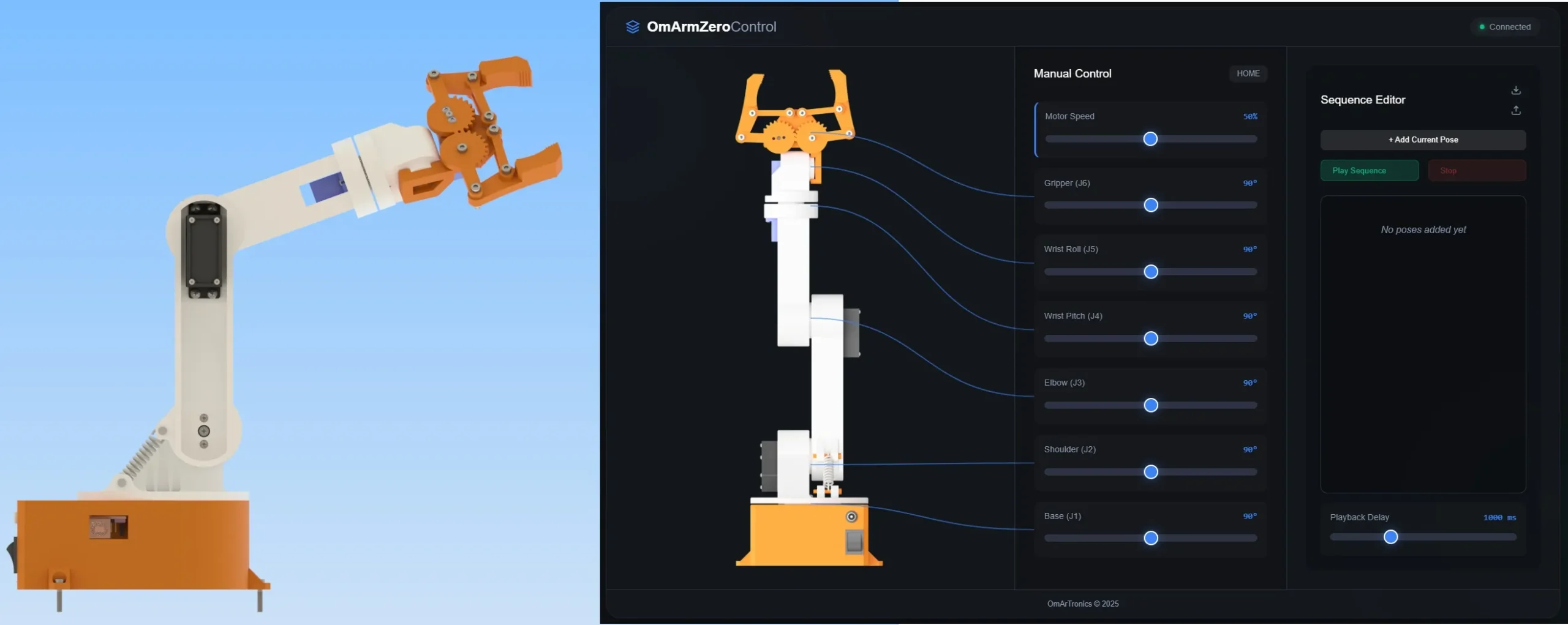
In my testing, the web GUI responds without noticeable lag. The 50Hz PCA9685 update rate helps keep movements smooth even over WiFi.
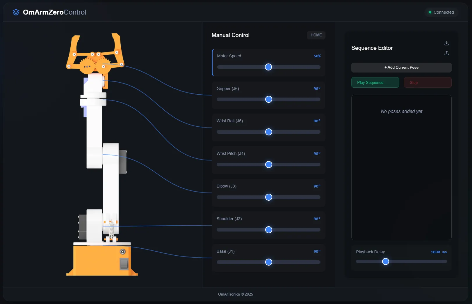
Here’s what the interface looks like on a desktop browser. The left side shows six sliders (one per joint), a speed control, and the Home button. The right side has the sequence editor where you can record, play back, and export movement sequences as JSON.
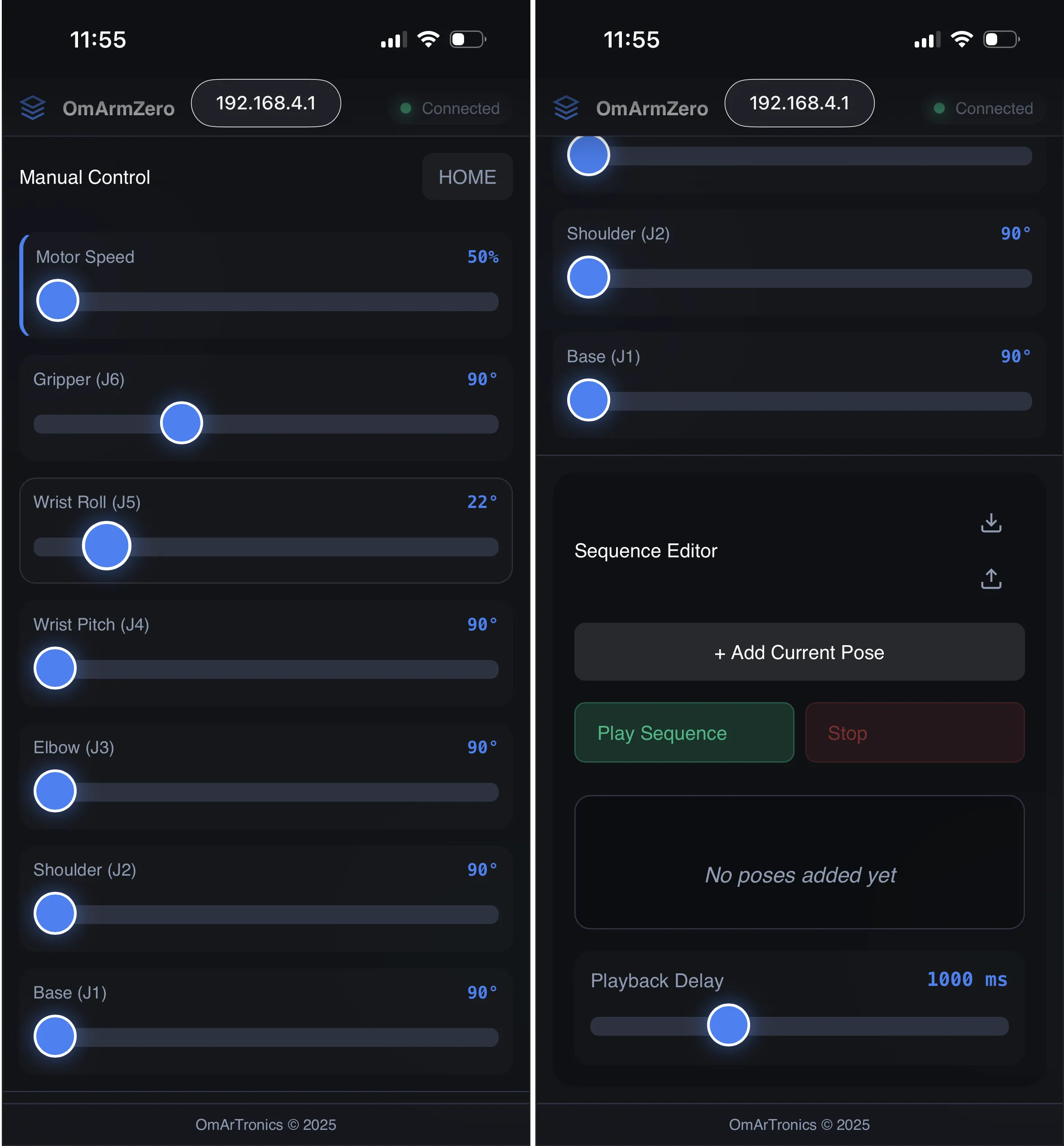
The same interface on a phone. The layout is responsive — sliders stack vertically and the sequence editor moves below the controls. I use the mobile version most of the time because you can hold the phone in one hand and watch the arm move with the other.
9. Testing and validation
You’ve assembled the arm, loaded the firmware, and everything should work. But let’s test it systematically to make sure.
Servo range test
Each servo has a theoretical range of 0-180 degrees. But mechanical constraints and print tolerances might reduce that. For each joint, send it to 0, then to 180, and check that it reaches the ends without binding or damage.
Serial commands:
1,0    (J1 fully counterclockwise)
1,180  (J1 fully clockwise)
2,0    (J2 lowered)
2,180  (J2 raised)
3,0    (J3 elbow down)
3,180  (J3 elbow up)
4,0    (J4 wrist pitch down)
4,180  (J4 wrist pitch up)
5,0    (J5 wrist roll left)
5,180  (J5 wrist roll right)
6,0    (Gripper open)
6,180  (Gripper closed)
After each command, listen for any grinding noise. Feel the joint by hand to check for binding. If a joint doesn’t reach the limit smoothly, loosen the fasteners and try again. Check that servo horns are fully seated on the servo shafts.
Accuracy test
Command a specific angle and measure the actual angle with a protractor. The arm should hit the target angle within 5 degrees. If it’s consistently off by the same amount, the servo might be misaligned. Check the horn centering step from assembly.
Speed test
Send a 0-to-180 sweep and time it:
1,0    (note the time)
1,180  (note the new time)
At default speed (5 deg/20ms), that’s 250 deg/s. A 180-degree sweep should take about 720 milliseconds. If it’s faster or slower, adjust the moveSpeed parameter via the SPEED command.
Payload test
This is the critical test. The gripper is 50g. You’ll hang weights from it and check that the arm holds steady.
At home position (all joints 0 degrees), hold a 50g weight in the gripper and check for drift. The arm should hold position without shaking.
Now lift the arm to full extension (J2 at 45, J3 at 135). Hold the 50g weight. No problem.
Try 100g. The arm should hold at full extension with only slight deflection. No strain on the servos.
Try 150g with the spring assist engaged. The arm might tremble slightly, but it should hold. This is the design limit.
Try 200g. The servo strains audibly. The arm might drop slowly under load. This exceeds the spec. Don’t operate at 200g regularly.
WiFi range test
Once the web GUI is working, test it from different distances and walls:
- 2 meters away, line of sight: no perceptible delay, instant response.
- 5 meters away, through a wall: still fine. The AP has decent range.
- 10 meters away: response is noticeable but still works.
- Outside the house: depends on your router, but the access point is weak. Expect 10-20 meter range in open air.
Repeatability test
This tests whether the arm returns to the same position every time. Send the arm to a position (say, 45, 90, 90, 90, 90, 90), then home it, then return to the same position. Measure the error with a protractor or by eye. Repeat 10 times. Any drifting error indicates a servo problem or loose fastener.
Sequence playback test
Record a simple pick-and-place sequence: lower the arm, close the gripper, raise the arm, move to the side, lower, open gripper, return. Save it. Play it back 10 times and check for consistency. Any dropped steps or jitter indicates a firmware problem (usually a buffer overflow if the sequence is huge).
Test results summary
Here’s what I measured on a working OmArm Zero:
| Test | Result | Notes |
|---|---|---|
| Servo range | 0-180° full travel | No binding, smooth motion |
| Accuracy (static) | +/- 3 degrees | Within spec |
| Speed (0-180 sweep) | 750ms | Matches 5 deg/20ms theory |
| Payload 50g | Holds fine | No visible deflection |
| Payload 100g | Holds steady | Slight deflection at full reach |
| Payload 150g | Works with spring | Minor tremor, acceptable |
| Payload 200g | Servo strains | Not recommended |
| WiFi range | 15m line of sight | Typical for AP mode |
| Repeatability | +/- 2 degrees | Consistent over 10 cycles |
| Sequence playback | Perfect | No dropped frames |
If your arm matches these results, you’re good. If any test fails dramatically, troubleshoot:
Servo doesn’t move: Check wiring, I2C address, channel mapping. Try moving another servo on the same channel. If that works, the first servo is dead. If not, the channel isn’t outputting PWM.
Servo moves but is weak: Check the voltage with a multimeter. The power supply should be steady at 5V. If it’s sagging to 4V, the supply is undersized.
Servo is jittery: The PCA9685 has a built-in decoupling capacitor. Try reducing the movement speed (SPEED:2,20) to give the power supply time to respond.
WiFi is slow: Try moving the antenna (if external) or the arm itself away from metal objects. WiFi is 2.4GHz and gets blocked by metal.
10. What comes next for this ESP32 robotic arm
At this point you have a working 6-DOF arm with web control. That’s already useful, but the interesting stuff comes next.
Part 2: URDF and digital twin
The next post will cover exporting a URDF (Unified Robot Description Format) file from the CAD. URDF is the standard format for describing robot kinematics and dynamics. Once you have a URDF, you can visualize the arm in RViz (ROS visualization) and simulate it in Gazebo.
The URDF will include the DH parameters, mass properties, and joint limits. You’ll be able to click on any point in 3D space in RViz and see whether the arm can reach it. You’ll be able to simulate collisions with obstacles.
This is where the math from Section 2 becomes useful. The torque calculations will inform the simulation. The workspace analysis will tell you what tasks are feasible.
Part 3: ROS2 MoveIt and motion planning
ROS2 Jazzy is the latest robotics operating system. MoveIt is the standard motion planning library. Together, they let you specify a goal pose for the gripper and the arm automatically computes the joint angles needed to reach it (inverse kinematics).
This solves a major limitation of manual slider control: you don’t think in joint angles, you think in positions. “I want to grab the blue cube at coordinates (200, 100, 50).” MoveIt figures out how to move J2, J3, J4, J5 to reach that point.
I’ll also add gamepad control so you can drive the arm with a game controller instead of typing coordinates.
Part 4: Computer vision and autonomous pick-and-place
The last piece is perception — now published as Part 4. Mount a USB camera or a Raspberry Pi camera on the wrist. Use ArUco marker detection to identify objects and their poses. Train a small neural network to sort objects by color or shape.
The goal: place a red cube on the table, and the arm picks it up and drops it in a bin without you touching anything. That’s what this series is building toward.
Download project files
All CAD files (3D-printable STL and parametric STEP), firmware source code, web interface, Fritzing wiring diagrams, and a printable PDF build guide for this project are available for download. You can get the complete package from our shop or browse individual files on GitHub and Cults3D.
Get the OmArm Zero project files
- 12 STL files (print-ready, pre-oriented)
- STEP source files for Fusion 360 / FreeCAD
- ESP32 firmware (serial + WiFi web control)
- Fritzing wiring diagrams
- PDF build guide
Download from OmArTronics Shop • View on GitHub • Browse on Cults3D
The firmware is licensed under MIT. The CAD files are licensed under CC-BY-4.0. You’re free to modify, build, and share your own versions.
Final notes
Most of what I learned building this arm came from the mistakes. The shoulder servo being the bottleneck wasn’t obvious until I did the torque math. Understanding that the PCA9685 has a built-in decoupling capacitor saved an extra component. And the 5-DOF limitation turned out to be less of a limitation than I expected.
If you get stuck, check the GitHub issues first. If your question isn’t there, open one. I got hundreds of questions on the original 6-DOF arm and I try to answer them all.
If you build your own version or modify the design, I’d like to see it. Drop a comment below or tag me.
The whole series is now live: Part 2, Part 3 and Part 4. Subscribe to the OmArTronics mailing list if you want to know when it’s out.