
In this Arduino joystick servo control tutorial, you will build a two-axis servo system with an OLED display. Watch the video below for a full walkthrough, or alternatively, scroll down for the step-by-step instructions.

📋 Quick Summary
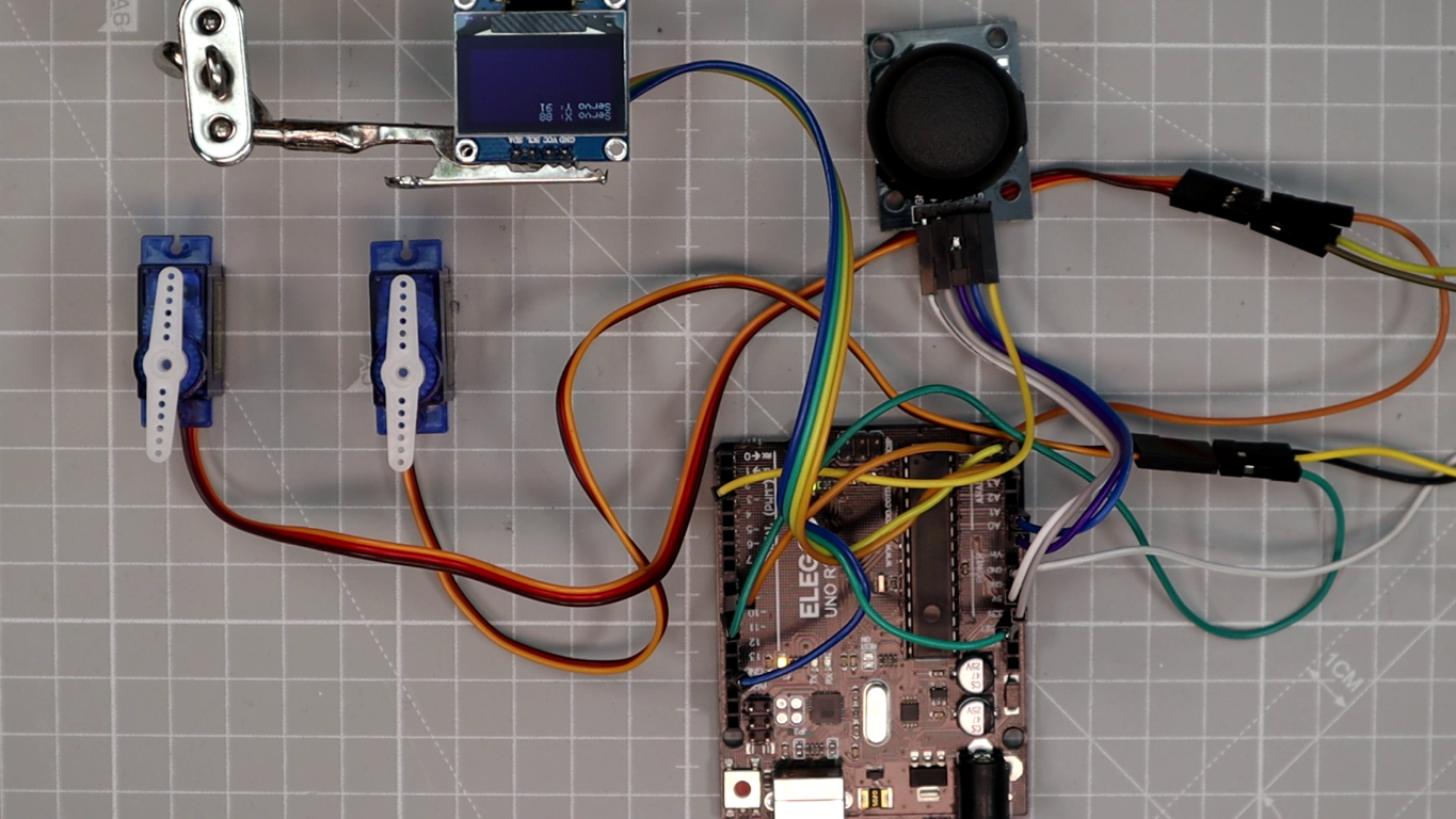
In this Arduino joystick servo control tutorial, you will learn how to move two SG90 servo motors with a two-axis joystick module and show the live servo angles on an SSD1306 OLED screen. The project runs on an Arduino Uno and covers analog input reading, servo PWM control, I2C OLED communication, and full wiring from scratch.
Want to control servo motors in real time with a joystick? In this Arduino joystick servo control tutorial, you will build a system that moves two servos with a joystick module while showing live angle feedback on an SSD1306 OLED screen. It is one of the better beginner projects for getting comfortable with analog input, servo output, and I2C display communication on Arduino.
If you are planning to build a robot arm or a pan-tilt camera mount, this servo motor with joystick Arduino project gives you the wiring, code, and calibration steps you need. By the end, you will have a working two-axis servo controller with live OLED feedback.
What you will learn in this Arduino joystick servo control tutorial
By following this OLED joystick servo Arduino tutorial, you will learn the following:
- How the joystick module provides two independent analog control axes (X and Y).
- How Arduino reads joystick analog values and maps them to servo angles using the
map()function. - How to wire two SG90 servo motors and an SSD1306 OLED display to an Arduino.
- How the OLED displays live servo angle feedback in real time.
- How to wire the system safely with an external 5 V power supply and common ground.
- How to reduce servo jitter, add a dead-zone, and tune the motion for your specific application.
How the joystick servo system works
This two servo joystick control Arduino project uses four components in a simple control loop:
- The joystick module has two potentiometers (VRx for the X-axis, VRy for the Y-axis). Each one outputs a voltage between 0 V and 5 V, which Arduino reads as analog values from 0 to 1023.
- The Arduino Uno reads both analog values from the joystick, then converts them into servo angles (0 to 180 degrees) using the
map()function, sends the angle commands to each servo, and updates the OLED display. - The two servo motors each receive a PWM signal from a dedicated Arduino pin. One servo responds to the joystick X-axis, and the other responds to the Y-axis, so you get independent two-axis control.
- The SSD1306 OLED display, connected via I2C (SDA and SCL), is a 128×64 pixel screen that shows each servo angle in real time. This makes it easy to confirm the system is working.
When you move the joystick, the Arduino reads the new position right away, calculates the matching servo angle, moves both servos, and refreshes the OLED. The whole loop runs roughly every 50 milliseconds, so the response feels immediate. If you are new to servo motor control with Arduino, start with our dedicated guide first.
Components needed for Arduino joystick servo control
Below is the full bill of materials for this SSD1306 servo joystick project. All parts are easy to find and inexpensive.
| Component | Quantity | Purpose | Notes |
|---|---|---|---|
| Arduino Uno (or Nano) | 1 | Main microcontroller board | Any ATmega328P-based Arduino will work |
| Joystick module (XY + SW) | 1 | Two-axis analog input | Provides VRx, VRy, and optional push button |
| Servo motor (SG90 or MG90S) | 2 | Actuators for X and Y axes | Small hobby servos rated for 4.8–6 V |
| OLED display (SSD1306, I2C) | 1 | Real-time angle feedback display | 128×64 pixels, 3.3–5 V compatible |
| Breadboard + jumper wires | – | Wiring connections | Use pin-to-pin and pin-to-socket jumper wires |
| External 5 V power supply | 1 | Stable servo power | At least 1 A recommended for two servos |
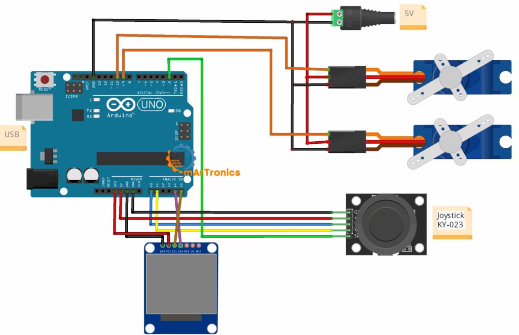
Arduino joystick servo control wiring diagram
Use the wiring table below to connect all components. If you are new to Arduino programming and wiring basics, however, review our beginner guide first.
| Component Pin | Arduino Pin | Notes |
|---|---|---|
| Joystick VRx | A0 | X-axis analog output |
| Joystick VRy | A1 | Y-axis analog output |
| Joystick SW | D2 (optional) | Push button – not used in this sketch |
| Servo 1 Signal | D9 | PWM output for X-axis servo |
| Servo 2 Signal | D10 | PWM output for Y-axis servo |
| OLED SDA | A4 | I2C data line |
| OLED SCL | A5 | I2C clock line |
| Servo +V (both) | External 5 V | Do not power servos from the Arduino 5 V pin |
| Servo GND (both) | Common GND | Connect external supply GND to Arduino GND |
Important wiring notes:
- External 5 V power for servos: Servo motors draw a lot of current, especially under load. As a result, powering them from the Arduino USB supply can cause voltage drops, servo jitter, or board resets. Always use a separate 5 V supply rated for at least 1 A.
- Common ground: The external power supply GND, the Arduino GND, and all component GND pins must be connected together. Without a common ground, the signals will not be referenced correctly, and as a consequence, the circuit will not work.
- I2C pull-ups: Most SSD1306 OLED breakout boards include built-in pull-up resistors on SDA and SCL. If your display does not have them, add 4.7 kΩ pull-ups to 3.3 V or 5 V.
Programming the Arduino for joystick servo control
The sketch below reads the joystick, maps the analog values to servo angles, drives both servos, and updates the OLED display in a continuous loop. Before uploading, make sure you have these libraries installed in the Arduino IDE: Servo.h (built-in), Adafruit_GFX, and Adafruit_SSD1306. You can install the Adafruit libraries through the Library Manager.
Full Code and GitHub Repository
You can download the full sketch from the GitHub repository.
#include <Servo.h>
#include <Adafruit_GFX.h>
#include <Adafruit_SSD1306.h>
// OLED setup
#define SCREEN_WIDTH 128
#define SCREEN_HEIGHT 64
Adafruit_SSD1306 display(SCREEN_WIDTH, SCREEN_HEIGHT, &Wire, -1);
// Servo setup
Servo servoX;
Servo servoY;
int joyX = A0;
int joyY = A1;
int servoXPin = 9;
int servoYPin = 10;
void setup() {
  servoX.attach(servoXPin);
  servoY.attach(servoYPin);
  // OLED init
  if(!display.begin(SSD1306_SWITCHCAPVCC, 0x3C)) {
    for(;;); // Halt if display not found
  }
  display.clearDisplay();
  display.setTextSize(1);
  display.setTextColor(SSD1306_WHITE);
}
void loop() {
  int xVal = analogRead(joyX);
  int yVal = analogRead(joyY);
  int angleX = map(xVal, 0, 1023, 0, 180);
  int angleY = map(yVal, 0, 1023, 0, 180);
  servoX.write(angleX);
  servoY.write(angleY);
  // OLED output
  display.clearDisplay();
  display.setCursor(0,0);
  display.print("Servo X: "); display.println(angleX);
  display.print("Servo Y: "); display.println(angleY);
  display.display();
  delay(50); // small debounce
}
Code Explanation
Library Includes and Setup
The sketch uses three libraries. First, Servo.h provides the Servo class for controlling standard hobby servos with PWM. Then, Adafruit_GFX.h is the core graphics library that handles drawing functions like text, shapes, and pixels. Finally, Adafruit_SSD1306.h is the driver for SSD1306-based OLED displays over I2C. The display is initialized at I2C address 0x3C, which is the default for most 128×64 SSD1306 modules.
Joystick Analog Reading
The analogRead(joyX) and analogRead(joyY) calls read the voltage on pins A0 and A1. Because the joystick potentiometers output a voltage from 0 V (one extreme) to 5 V (the other extreme), the Arduino ADC converts this to a value from 0 to 1023. At center position, you will typically read values around 500 to 520.
Angle Mapping with map()
The map(xVal, 0, 1023, 0, 180) function linearly scales the raw joystick value (0 to 1023) to a servo angle (0 to 180 degrees). For example, when the joystick is pushed fully left, the servo goes to 0 degrees. Fully right goes to 180 degrees. As a result, the center position maps to roughly 90 degrees. The same mapping applies independently to the Y-axis servo.
Servo Output
The servoX.write(angleX) and servoY.write(angleY) commands send the calculated angle to each servo. Behind the scenes, the Servo library handles the PWM signal generation. Since each servo is attached to its own pin (D9 and D10), you get independent control over both axes.
OLED Display Update
On every loop iteration, the OLED is cleared with display.clearDisplay(), the cursor resets to the top-left corner, and both servo angles get printed. After that, the display.display() call pushes the buffer to the screen. This gives you live visual feedback of the servo positions, which is especially handy during calibration and testing.
Why delay(50) Is Used
The 50-millisecond delay at the end of the loop is a simple debounce and rate limiter. Without it, the loop runs extremely fast, sending rapid PWM updates that can cause servo jitter and unnecessary OLED flicker. Fifty milliseconds is a good starting point, but if your servos still jitter, try bumping it to 80 or 100 ms.
When a Dead-Zone Is Useful
Joystick potentiometers often produce slightly fluctuating values around center position, even when nobody is touching them. Consequently, the servos twitch at rest. You can fix this by adding a dead zone in the code: if the joystick value is between 480 and 540, force the angle to 90 degrees instead of mapping it. As a result, the servo stays still when the joystick is centered.
How to test and calibrate your Arduino joystick servo control
Once you have uploaded the sketch, follow these steps to verify and fine-tune your Arduino servo control with OLED system.
Step 1: Test the X-Axis Servo
First, move the joystick left and right. The servo connected to pin D9 should rotate smoothly from 0 to 180 degrees. At the same time, watch the OLED to confirm that the “Servo X” value changes as you move the stick.
Step 2: Test the Y-Axis Servo
Next, move the joystick up and down. The servo on pin D10 should rotate accordingly. Also verify that the “Servo Y” value on the OLED updates correctly.
Step 3: Verify OLED Output
With the joystick at center, both servo values should read approximately 90 degrees on the OLED. However, if the display stays blank, double-check your SDA/SCL wiring and I2C address (most modules use 0x3C, but some use 0x3D).
Step 4: Add a Dead-Zone for Center Stability
If the servos twitch slightly when the joystick is at rest, add a dead zone. Before calling map(), check whether the raw joystick value is between roughly 480 and 540. If so, set the angle to 90 degrees directly. In this way, you eliminate jitter from small analog noise at center position.
Step 5: Invert Axis Mapping if Needed
If the servo moves in the opposite direction from what you expect, swap the mapping range. For example, change map(xVal, 0, 1023, 0, 180) to map(xVal, 0, 1023, 180, 0). This reverses the servo direction for that axis.
Step 6: Limit Servo Angles for Mechanical Constraints
If your mechanical setup cannot handle the full 0 to 180 degree range (for example, a pan-tilt mount that only allows 30 to 150 degrees), then change the output range in the map() call. For example: map(xVal, 0, 1023, 30, 150). As a result, the servo will not push against physical stops, which can damage gears over time.
Troubleshooting your Arduino joystick servo control setup
Below are the most common issues and fixes for an Arduino joystick servo control setup.
OLED Stays Blank
First, check that SDA is connected to A4 and SCL to A5. Then verify the I2C address in the code matches your display (usually 0x3C). Also make sure the Adafruit SSD1306 and Adafruit GFX libraries are installed. If the display worked before and stopped, try a different I2C address (0x3D).
Servos Jitter at Center Position
This is the most common issue, and it is almost always caused by powering servos from the Arduino 5 V pin. Instead, use an external 5 V power supply rated for at least 1 A. In addition, consider adding a dead zone in the code around the joystick center values.
Servos Move in the Wrong Direction
Simply swap the output range in your map() function. For example, change map(xVal, 0, 1023, 0, 180) to map(xVal, 0, 1023, 180, 0) for the affected axis.
One Servo Does Not Respond
Start by checking the signal wire connection for that servo. Make sure the correct Arduino pin is being used (D9 or D10). Then test the servo on its own with a simple sweep sketch to confirm it is not defective. Also verify that the servo GND is connected to the common ground.
Display Initializes but Shows Nothing Useful
If the screen lights up but shows garbled characters, first ensure display.clearDisplay() is called at the start of each loop. Also verify that display.setTextSize(1) and display.setTextColor(SSD1306_WHITE) are in the setup() function. Additionally, a missing display.display() call will result in nothing appearing on screen.
System Resets When Both Servos Move
This is a clear sign of insufficient power. Because two servos moving at the same time can draw up to 1 A or more under load, the Arduino USB port simply cannot supply enough current. Therefore, use a dedicated 5 V power supply for the servos, and only share the ground with the Arduino.
Joystick Values Feel Noisy
Some joystick modules produce slightly noisy analog readings. To fix this, you can smooth the values by averaging multiple readings, or apply a simple software filter. Furthermore, a dead zone at center position helps. Also keep the joystick wires short and away from motor wires to reduce electrical noise.
Frequently asked questions about Arduino joystick servo control
Yes. This project works with any Arduino that has at least two analog inputs and two PWM-capable digital outputs. For instance, Arduino Nano, Mega, and Leonardo are all compatible. However, if you use a board with different I2C pins, update the SDA/SCL connections accordingly.
A standard two-axis joystick controls up to two servos (one per axis). To control more servos, you can add more joysticks, use the push-button for mode switching, or use a PCA9685 servo driver with additional input methods.
No. The OLED is optional and just provides visual feedback. The joystick and servos will work without the display. That said, the OLED makes testing and calibration much easier because you can see the live servo angles.
Jitter with an external supply usually comes from noisy analog readings or missing dead zone logic. To fix this, add a dead zone around center values (roughly 480 to 540) to prevent small fluctuations from moving the servos. You can also add a capacitor (100 uF or larger) across the servo power lines to smooth voltage fluctuations.
Yes, but MG996R servos draw much more current (up to 2.5 A under stall). You will need a more powerful external supply. The code remains the same because both servo types accept standard PWM signals.
More questions about joystick servo control
Modify the output range in the map() function. For example, map(xVal, 0, 1023, 30, 150) limits the servo to the 30–150 degree range instead of the full 0–180 degrees.
Most 128×64 SSD1306 modules use I2C address 0x3C. Some modules use 0x3D. If your display does not initialize, try both addresses. You can also run an I2C scanner sketch to detect connected devices.
Absolutely. You can replace the physical joystick with Bluetooth input from a smartphone app using an HC-05 Bluetooth module. As a result, you get wireless servo control. Our Bluetooth tutorial covers the full setup.
The joystick SW pin outputs LOW when pressed. Connect it to a digital pin (for example D2) with an internal pull-up resistor enabled (pinMode(2, INPUT_PULLUP)). You can then use it to toggle modes, save positions, or reset the servos to center.
Yes, this is a great starting point for that. A two-axis joystick can control two joints of a robotic arm. For a full 6-DOF arm, you would need more joysticks or a potentiometer-based control system. Our complete robotic arm tutorial shows how to scale this up to a full build.
Flickering is usually caused by voltage drops when servos draw current. To prevent this, make sure the servos are on a separate power supply and not sharing the 5 V line with the OLED. In addition, adding a decoupling capacitor near the OLED power pins can help stabilize the display.
Resources and next steps for Arduino joystick servo control
Project Code
Download the full sketch from the GitHub repository.
Related OmArTronics Tutorials
- Arduino Servo Control Guide: SG90, PWM, and PCA9685 – Learn servo fundamentals in depth.
- Arduino Programming Basics – Essential guide if you are new to Arduino code.
- Arduino IR Remote Tutorial: Control an LED, Then Add a Servo Door – Another servo-based project with IR input.
- DIY 6-DOF Robotic Arm – 3D Print, Wire, and Program – Scale up from two servos to six joints.
- DIY 6-DOF Robotic Arm with Bluetooth Control – Add wireless smartphone control to a full arm.
- Arduino and HC-05/HC-06 Bluetooth Module Complete Tutorial – Add Bluetooth to any Arduino project.
- Arduino Radar with HC-SR04 and Servo Motor – Another servo-based scanning project.
- Arduino Password Door Lock with Keypad and LCD – Servo-actuated door lock project.
Suggested Next Upgrades
- Use the joystick SW pin to save servo positions or toggle between control modes.
- Replace the physical joystick with a smartphone app via HC-05 for wireless servo control.
- 3D-print or build a two-axis camera mount and control it with this exact circuit.
- Add more servos and joysticks to build a multi-DOF robotic arm.
- Store servo positions in EEPROM and replay them for automated motion sequences.
Conclusion
At this point, you have a working Arduino joystick servo control system with live OLED feedback. Along the way, you covered how the joystick provides two analog axes, how Arduino maps those values to servo angles, how to wire servos safely with external power, and how the SSD1306 OLED shows position data.
This two servo joystick control Arduino project is a good starting point for more advanced builds. From here, you could turn it into a robot arm or a pan-tilt camera mount. Try the suggested upgrades above, and share your results in the comments.