

📋 Quick Summary
Build a complete 6-DOF robotic arm with Bluetooth smartphone control. This guide upgrades the basic 3D-printed robotic arm with an HC-05 Bluetooth module and a custom MIT App Inventor app, enabling wireless control of all six servo joints. Covers wiring with PCA9685 servo driver, Arduino Mega programming, and app setup.
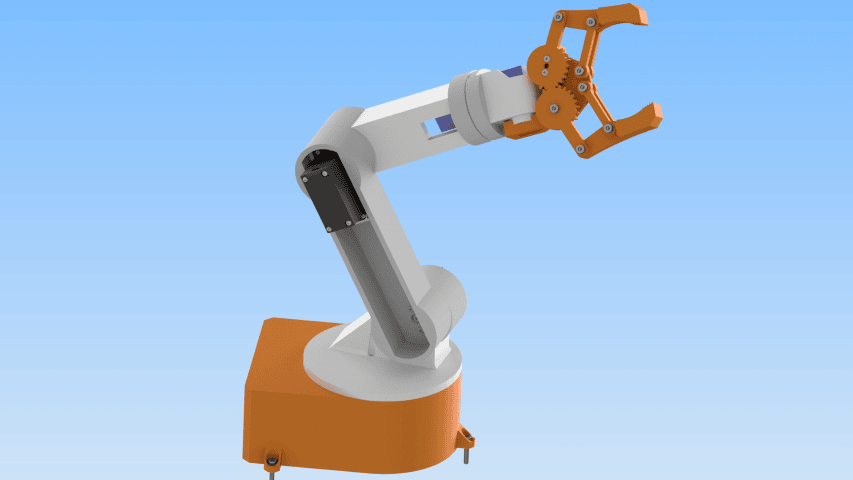
In this hands-on tutorial, you will learn, step by step, how to build a DIY 6-DOF robotic arm with full Bluetooth smartphone control from scratch. This project takes the potentiometer-controlled robotic arm from our previous build and upgrades it with wireless Bluetooth communication. Instead of turning physical knobs, you now control all six joints directly from a custom Android app on your phone.
The system combines 3D-printed mechanical parts, an Arduino Uno, a PCA9685 servo driver, an HC-05 Bluetooth module, and a custom MIT App Inventor application. The result is a wireless Bluetooth controlled robotic arm that saves, plays back, and loops movement sequences. You get a programmable robot arm you can operate from your couch.
If you like building things and want to learn some robotics along the way, this guide covers the whole process: CAD design, 3D printing, assembly, wiring, Arduino code, Bluetooth setup, and app development. All source code, STL files, and the app are available for download on our GitHub repository. You can also get the STL files from Cults3D or from our OmArTronics Shop.
What You Will Learn in This DIY 6-DOF Robotic Arm Project
By the end of this tutorial, you will have hands-on experience with several areas of mechatronics and robotics. You will learn how to design parametric robot parts in Autodesk Inventor and 3D print components with tight tolerances. You will also wire an Arduino to the PCA9685 servo driver and HC-05 Bluetooth module, write code for real-time Bluetooth commands with smooth servo interpolation, build a working Android app in MIT App Inventor, and calibrate the arm for repeatable movement.
What Is a 6-DOF Robotic Arm?
DOF stands for Degrees of Freedom. It defines how many independent axes a robot can move along. In our design, the 6-DOF robotic arm has six servo-driven joints: five rotational axes that control the arm’s pose, plus one gripper joint that opens and closes the end effector. The five axes (base rotation, shoulder, elbow, wrist pitch, and wrist roll) give the arm 5 DOF positioning, while the sixth joint operates the gripper to grasp objects. Three MG996R high-torque servos power the base, shoulder, and elbow, while three SG90 micro servos handle the wrist pitch, wrist roll, and gripper. As a result, this combination provides enough torque for the heavy-lift joints and enough precision for the lighter end-effector movements.
For a deeper introduction to how servo motors work and how to control them with Arduino, see our servo motor control guide.
DIY 6-DOF Robotic Arm: Project Overview and System Architecture
In total, the project breaks into five phases: mechanical design, 3D printing, assembly, electronics wiring with Bluetooth, and software for both the Arduino and the phone app. At the center of the system is the Arduino Uno. It talks to the PCA9685 servo driver over I2C to generate six independent PWM signals. At the same time, it receives movement commands wirelessly from your phone via the HC-05 Bluetooth module.
On the phone side, MIT App Inventor also gives you a drag-and-drop environment for building the interface. The app sends text commands over Bluetooth: slider values for real-time joint control, plus commands for saving poses, playing sequences, stopping playback, resetting memory, and toggling loop mode. When a command arrives, the Arduino parses it, maps it to the right servo channel, and then runs a smooth interpolated movement so the arm does not jerk.
Complete Bill of Materials for the DIY 6-DOF Robotic Arm
Before you start building, gather all the components in the table below. That way, you avoid frustrating mid-build pauses. Besides the parts from the previous potentiometer-controlled build, this Bluetooth upgrade adds an HC-05 module and removes the six potentiometers since control now happens wirelessly from the app.
DIY 6-DOF Robotic Arm: Parts and Components List
| Item | Quantity | Part | Description |
|---|---|---|---|
| 1 | 1 | Base_1 | Base platform |
| 2 | 1 | base_link_upper1 | Upper base section |
| 3 | 1 | arm_link_1 | First arm link |
| 4 | 1 | arm_link_2 | Second arm link |
| 5 | 1 | arm_link_3 | Third arm link |
| 6 | 1 | gripper_base | Gripper base |
| 7 | 1 | Gripper_2 | Gripper finger |
| 8 | 1 | Gear_right | Gripper gear (right) |
| 9 | 1 | Gear_left | Gripper gear (left) |
| 10 | 1 | Gripper | Gripper assembly |
| 11 | 4 | Link | Gripper link parts |
| 12 | 2 | Spacer | Gripper spacers |
| 13 | 3 | MG996R Servo Motor | High-torque servo (base, shoulder, elbow) |
| 14 | 3 | SG90 Micro Servo Motor | Micro servo (wrist, gripper) |
| 15 | 14 | ANSI B18.6.4 No.2-32 3/8″ | Truss head screw, No.2-32 |
| 16 | 2 | ANSI B18.6.4 No.2-32 1/4″ | Truss head screw, No.2-32 |
| 17 | 3 | DIN 7985 M1.6×2-Z | M1.6×2 cross-recess screw |
| 18 | 7 | ISO 4762 M3x16 (AS 1420) | M3x16 hex socket screw |
| 19 | 12 | ISO 4032 M3 (AS 1112) | M3 hex nut |
| 20 | 2 | ANSI B18.6.4 No.2-32 1/2″ | Truss head screw, No.2-32 |
| 21 | 3 | MG955 Horn | Horn for MG996R |
| 22 | 3 | DIN 7985 M3x6-Z | M3x6 cross-recess screw |
| 23 | 3 | SG90 Servo Horn | Horn for SG90 |
| 24 | 2 | ANSI B18.6.4 No.2-32 3/8″ | Truss head screw, No.2-32 |
| 25 | 12 | ANSI B18.6.4 No.3-28 1/2″ | Truss head screw, No.3-28 |
| 26 | 1 | Ball Bearing 6806ZZ (30x42x7) | Deep-groove bearing (30x42x7) |
| 27 | 1 | Arduino Uno or Mega | Main controller |
| 28 | 1 | PCA9685 Servo Driver Board | 16-ch PWM driver (I2C) |
| 29 | 6 | HC-05 Bluetooth module | Bluetooth module for wireless control |
| 30 | 1 | Breadboard | Wiring base for connections |
| 31 | 1 | 5V 10A Power Supply | Servo power source |
| 32 | 1 | Jumper Wires (male-male) | Arduino to PCA9685 connections |
| 33 | 1 | Jumper Wires (male-female) | General wiring connections |
| 34 | 1 | Wooden Board | Arm mounting platform |
Mechanical Design of the DIY 6-DOF Robotic Arm in Autodesk Inventor
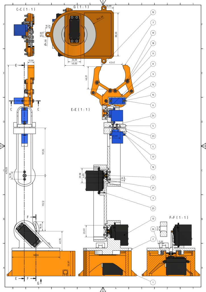
First, you model every component in Autodesk Inventor. This parametric CAD software lets you set exact dimensions, add fillets for strength, and also check part fit before you print anything. If you are new to Inventor or 3D printing, check out our Introduction to 3D Printing and 3D Design with Inventor before starting.
Two servo types drive the design choices here. The SG90 micro servos measure 23 x 12 x 29 mm, which makes them a good fit for the lighter wrist and gripper joints. By contrast, the MG996R servos deliver up to 11 kg-cm of torque with metal gears. Because of that, they are the right choice for the base, shoulder, and elbow, since those joints carry the full weight of the arm. As a consequence, every mount pocket, horn attachment point, and bearing seat matches the exact datasheet dimensions for these two servo types.
Below, the technical drawing shows part dimensions, sectional views, and how parts fit together. Use it as a reference when you check print accuracy.
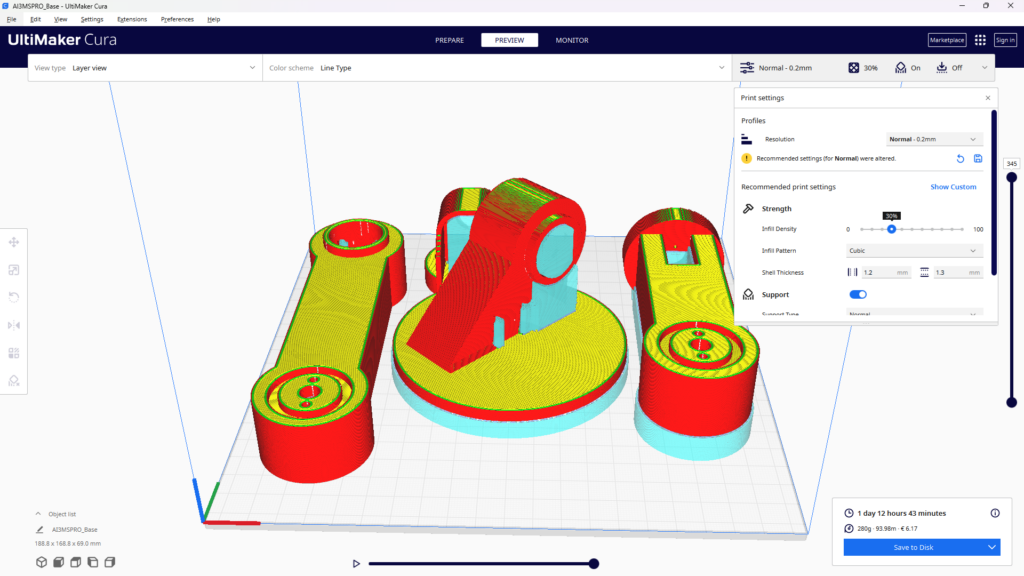
3D Printing the DIY 6-DOF Robotic Arm Components
After you export the STL files from Inventor, it is time to start printing. PLA filament works well because it prints easily and holds tight dimensions. For structural parts like the base and arm links, use a layer height of 0.2 mm and at least 40 percent infill. For thinner parts like gripper gears, however, 20 percent infill is enough and saves material.
Pay close attention to the servo mount pockets. They need to be accurate so the motors press-fit snugly without wobble. After printing, do some light cleanup: remove supports, sand mating surfaces with 220-grit, and test-fit each servo before you move on to assembly. If a pocket runs too tight, a quick pass with a hobby knife or needle file is faster than reprinting.

Servo Motor Selection: SG90 vs MG996R for the DIY 6-DOF Robotic Arm
Picking the right servo for each joint matters. The three lower joints (base, shoulder, elbow) carry the full weight of everything above them, so they need the MG996R and its 11 kg-cm stall torque. On the other hand, the three upper joints (wrist pitch, wrist roll, gripper) carry very little load. So the lightweight SG90 at 1.8 kg-cm is more than enough, and it keeps the end of the arm light.
Both servo types accept standard 50 Hz PWM, so they plug right into the PCA9685 headers. However, the main difference for wiring is current: a single MG996R can pull up to 900 mA under load, while an SG90 draws about 200 mA. With six servos running at once, peak current can go past 3 A. Because of that, you need the external 5 V 10 A power supply. Do not try to power six servos from the Arduino’s 5 V pin.
Assembling Your DIY 6-DOF Robotic Arm Step by Step
Once every part is printed and test-fitted, you can start assembling. Work from the base upward, and always test each joint for smooth rotation before moving on. Take your time with screws because over-torquing into 3D printed plastic strips threads fast.

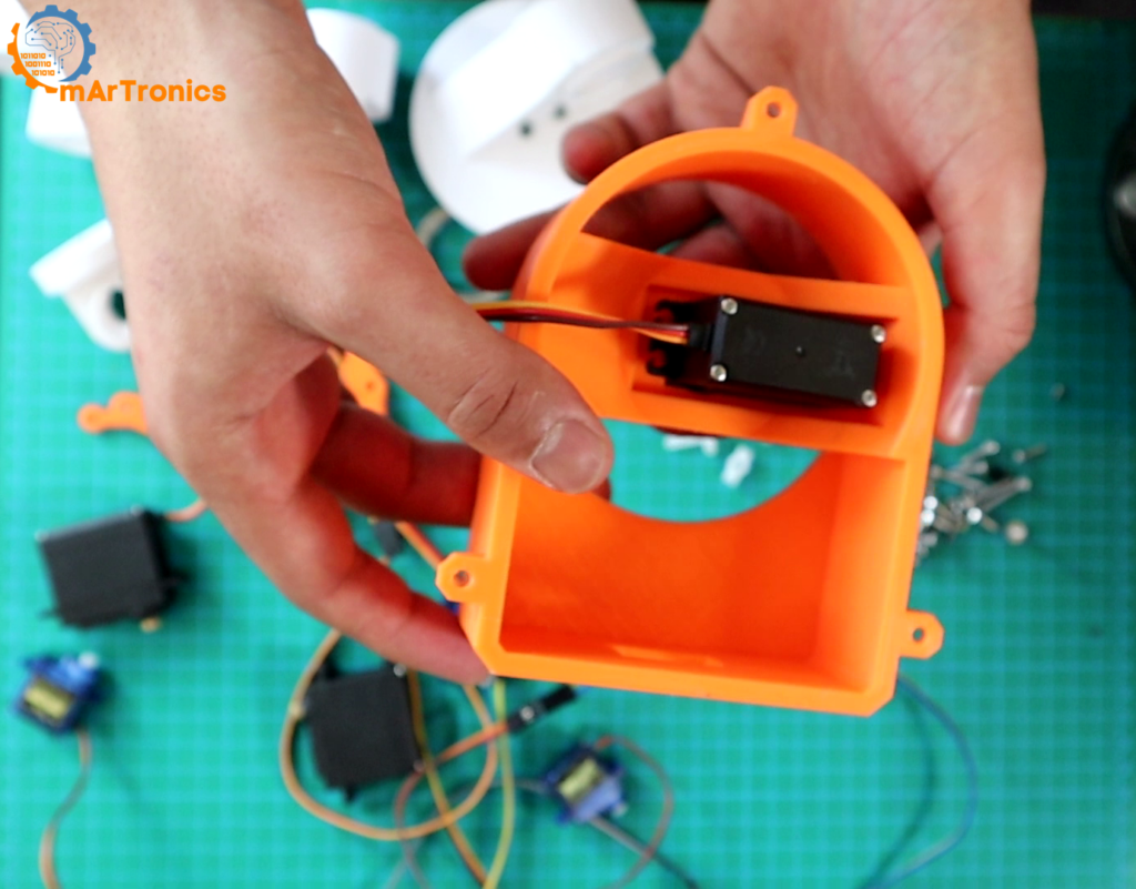
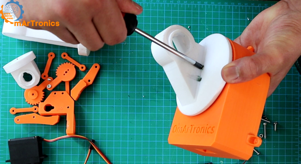
Step 1: Assembling the Base of the DIY 6-DOF Robotic Arm
The base is the foundation of the entire arm, so accuracy here matters. Start by installing the first MG996R servo into the base mount with the included screws. This servo gives you the full 180 degrees of base rotation. Then press-fit the deep-groove ball bearing (6806ZZ, 30 x 42 x 7 mm) into its seat on the base. Next, the bearing sits between the fixed base plate and the rotating upper platform. As a result, it reduces friction and extends the life of the joint. After that, attach the servo horn to the rotating upper platform using M2x12 self-tapping screws. This horn transfers all rotational force from the base servo to the rest of the arm.

Step 2: Mounting Servo Horns to the Robot Arm Links
Next, line up each servo horn with its arm link attachment point. Then secure it with two screws per horn. If the holes do not line up, the horn will bind and cause uneven movement. Double-check every connection before you tighten fully.
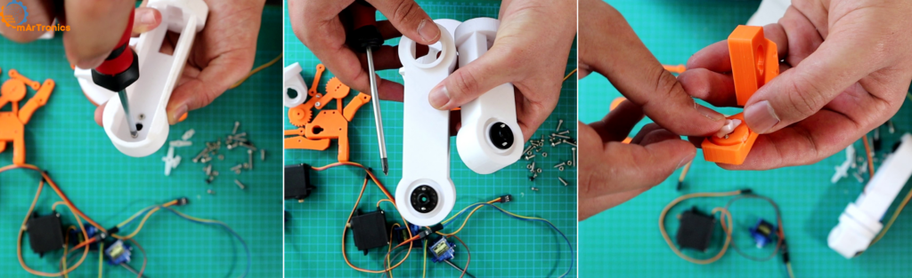
Step 3: Mounting Servo Motors to the Arm Links
Then seat each servo motor into its 3D printed pocket on the arm link. Also make sure the orientation is correct. Fasten with two screws per motor and test stability by pressing gently. The servo should not shift or rock. A solid motor mount is what gives you for precise, repeatable movements.

Step 4: Connecting the Robot Arm Links Together
Now join the link-and-servo assemblies together. Position the horn on one link so it slots into the next, then secure with screws. Tighten evenly so that the joints move smoothly across the full range.
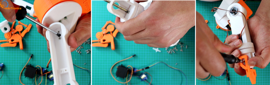
Step 5: Assembling the Gripper
Attach the gripper sub-assembly to the end link of the arm. The gripper uses an SG90 micro servo with a pair of 3D printed gears to open and close the fingers. Use M3x20 screws for the gripper joints. Before you move on, also make sure the fingers open and close freely.

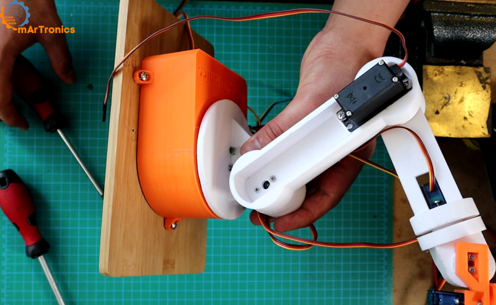
Step 6: Mounting the DIY 6-DOF Robotic Arm on a Wooden Base
Finally, mount the fully assembled arm onto a flat wooden board using M3x12 self-tapping screws. A solid base prevents the arm from tipping and also gives you a place to mount the breadboard, Arduino, and power supply.
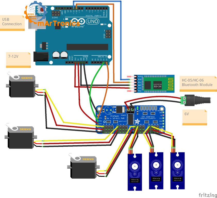
Electronics Wiring for the DIY 6-DOF Robotic Arm with Bluetooth
Now that the mechanical build is done, it is time to wire the electronics. This version adds an HC-05 module and also removes the six potentiometers from the original build. The control system has four parts: the Arduino Uno, the PCA9685 for PWM generation, the HC-05 for wireless communication, and a 5 V 10 A power supply for the servos.
Wiring Connections Table: Arduino to PCA9685
| Arduino Pin | PCA9685 Pin | Function |
|---|---|---|
| 5 V | VCC | Logic power for PCA9685 chip |
| GND | GND | Common ground |
| A4 (SDA) | SDA | I2C data line |
| A5 (SCL) | SCL | I2C clock line |
Wiring Connections Table: Arduino to HC-05 Bluetooth Module
| Arduino Pin | HC-05 Pin | Function |
|---|---|---|
| Pin 10 (SoftwareSerial RX) | TX | Receives data from Bluetooth |
| Pin 11 (SoftwareSerial TX) | RX (via voltage divider) | Sends data to Bluetooth |
| 5 V | VCC | Powers the HC-05 module |
| GND | GND | Common ground |
Servo Power and PCA9685 Connections
Next, connect each servo’s 3-pin plug into channels 0 through 5 on the PCA9685 board. Make sure the ground wire (brown or black) lines up with the bottom row of headers. After that, hook up the 5 V 10 A power supply to the PCA9685’s V+ and GND screw terminals. This way, the high-current servo loads stay separate from the Arduino, which prevents brownouts and erratic behavior.
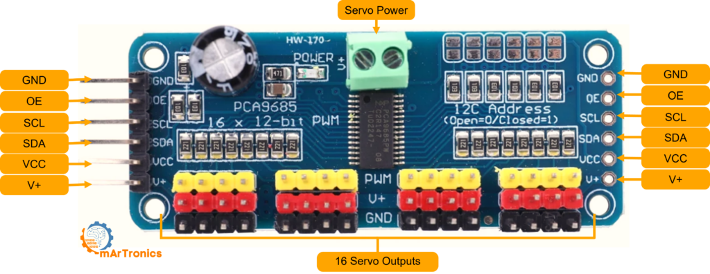
Understanding the PCA9685 Servo Driver for the DIY 6-DOF Robotic Arm
Why not just drive servos straight from the Arduino? You can drive one or two that way, but it gets limiting with six. On top of that, the Arduino Uno has only six PWM pins, and the built-in Servo library can conflict with timer features like tone() or some communication protocols. The PCA9685 solves this by moving all PWM generation to a dedicated I2C chip. It uses just two wires (SDA and SCL) no matter how many servos you control. It handles 16 channels per board, and you can daisy-chain up to 62 boards for 992 servos if you ever need that many.
PCA9685 Pinout Reference
First, GND is the common ground shared with the Arduino. OE (Output Enable) is active low. Leave it unconnected to keep all outputs on by default. Then, SCL and SDA are the I2C clock and data lines. In addition, VCC provides logic power at 3.3 to 5 V and powers only the PCA9685 chip, not the servos. Finally, V+ is the servo power rail. It accepts up to 6 V from your external supply through the screw terminal. Each channel has a 3-pin header that takes a standard servo connector.
Bluetooth Communication with the HC-05 Module
The HC-05 is a Bluetooth module that creates a wireless serial link between your Android phone and the Arduino. Since it runs at 3.3 V logic, the TX line from the Arduino (5 V) to the HC-05 RX pin needs a voltage divider with two resistors (1 kOhm and 2 kOhm). However, the HC-05 TX to Arduino RX line does not need a divider because 3.3 V is already high enough for the Arduino to read as logic HIGH.
In the code, we use SoftwareSerial on pins 10 and 11 instead of the hardware serial pins (0 and 1). This keeps hardware serial free for debugging with the Serial Monitor while Bluetooth runs on its own channel. The HC-05 defaults to 9600 baud, which matches the SoftwareSerial setup in our code. For a complete guide on HC-05 setup and AT commands, see our HC-05 Bluetooth module tutorial.
Arduino Programming for the DIY 6-DOF Robotic Arm with Bluetooth
The Arduino sketch is the brain of this DIY 6-DOF robotic arm. It handles Bluetooth communication, command parsing, servo control with smooth interpolation, and also pose saving and sequence playback. Below is the complete source code. After the code, you will find a section-by-section explanation.
Full Arduino Source Code for the Bluetooth Robotic Arm
Upload this sketch to your Arduino Uno or Mega. Before compiling, make sure the Adafruit PWM Servo Driver Library is installed through the Arduino Library Manager. Wire and SoftwareSerial already come with the IDE. The code and all project files are also available on the GitHub repository.
Complete Arduino Sketch
#include <Wire.h>
#include <Adafruit_PWMServoDriver.h>
#include <SoftwareSerial.h>
// Constants and definitions
const int numServos = 6;
const int maxConfigurations = 10;
const int stepDelay = 10;
const int stepSize = 1;
// Servo channels on the PCA9685
const int servoChannels[numServos] = {0, 4, 8, 9, 12, 13};
// Storage structures
int savedConfigurations[maxConfigurations][numServos];
int currentServoPositions[numServos] = {375, 375, 375, 375, 375, 375};
int configCount = 0;
bool isPlaying = false;
bool loopPlayback = false;
bool stopPlaying = false;
int currentPoseIndex = 0;
bool initialized = false;
Adafruit_PWMServoDriver pwm = Adafruit_PWMServoDriver();
SoftwareSerial BTSerial(10, 11);
// Setup initialization
void setup() {
  Serial.begin(9600);
  BTSerial.begin(9600);
  pwm.begin();
  pwm.setPWMFreq(60);

  for (int i = 0; i < numServos; i++) {
    pwm.setPWM(servoChannels[i], 0, currentServoPositions[i]);
  }
  initialized = true;
  Serial.println("Bluetooth Servo Controller started. Waiting for commands...");
}
// Main loop
void loop() {
  if (BTSerial.available()) {
    String input = BTSerial.readStringUntil('n');
    input.trim();

    Serial.println("Received data: " + input);
    if (input.equalsIgnoreCase("S")) {
      saveCurrentPose();
    } else if (input.equalsIgnoreCase("P")) {
      startPlayingPoses();
    } else if (input.equalsIgnoreCase("R")) {
      resetPoses();
    } else if (input.equalsIgnoreCase("St")) {
      stopPlayingPoses();
    } else if (input.equalsIgnoreCase("LoopON")) {
      loopPlayback = true;
      Serial.println("Loop playback enabled.");
    } else if (input.equalsIgnoreCase("LoopOFF")) {
      loopPlayback = false;
      Serial.println("Loop playback disabled.");
    } else if (input.indexOf(',') > 0) {
      processLastValue(input);
    } else {
      Serial.println("Unknown command: " + input);
    }
  }
  if (isPlaying && !stopPlaying) {
    if (loopPlayback) {
      playPosesInLoop();
    } else {
      playNextPose();
    }
  }
}
Servo Control and Command Processing Functions
// Process servo commands
void processLastValue(String command) {
    int lastCommaIndex = command.lastIndexOf(',');
    if (lastCommaIndex > 0 && lastCommaIndex < command.length() - 1) {
        int servoIndex = command.substring(0, lastCommaIndex).toInt() - 1;
        float lastValue = command.substring(lastCommaIndex + 1).toFloat();

        int targetPos = (int)lastValue;

        int targetPwmValue = map(targetPos, 0, 180, 150, 600);

        moveToPositionSmoothly(servoIndex, targetPwmValue);
    } else {
        Serial.println("Invalid command for servo control: " + command);
    }
}

// Smooth movement function
void moveToPositionSmoothly(int servoIndex, int targetPwmValue) {
    int currentPwmValue = currentServoPositions[servoIndex];
    if (targetPwmValue > currentPwmValue) {
        for (int pos = currentPwmValue; pos <= targetPwmValue; pos += stepSize) {
            pwm.setPWM(servoChannels[servoIndex], 0, pos);
            delay(stepDelay);
        }
    } else {
        for (int pos = currentPwmValue; pos >= targetPwmValue; pos -= stepSize) {
            pwm.setPWM(servoChannels[servoIndex], 0, pos);
            delay(stepDelay);
        }
    }
    currentServoPositions[servoIndex] = targetPwmValue;
    Serial.println("Servo " + String(servoIndex + 1) + " set to PWM value: " + String(targetPwmValue));
}
Pose Save, Playback, and Reset Functions
// Save pose function
void saveCurrentPose() {
    if (configCount < maxConfigurations) {
        for (int i = 0; i < numServos; i++) {
            savedConfigurations[configCount][i] = currentServoPositions[i];
            Serial.print("Servo "); Serial.print(i + 1);
            Serial.print(" saved at PWM value: ");
            Serial.println(savedConfigurations[configCount][i]);
        }
        configCount++;
        Serial.println("Pose saved. Total saved poses: " + String(configCount));
    } else {
        Serial.println("Memory full, cannot save more poses.");
    }
}

// Start playback
void startPlayingPoses() {
    if (configCount == 0) {
        Serial.println("No poses saved, nothing to play.");
        return;
    }
    Serial.println("Playback of saved poses started...");
    isPlaying = true;
    stopPlaying = false;
    currentPoseIndex = 0;
}

// Play next pose
void playNextPose() {
    if (currentPoseIndex < configCount) {
        Serial.println("Playing pose " + String(currentPoseIndex + 1));
        for (int i = 0; i < numServos; i++) {
            moveToPositionSmoothly(i, savedConfigurations[currentPoseIndex][i]);
        }
        delay(1000);
        currentPoseIndex++;
    } else {
        isPlaying = false;
        Serial.println("Playback of poses finished.");
    }
}

// Loop playback
void playPosesInLoop() {
    for (int j = 0; j < configCount; j++) {
        Serial.println("Playing pose " + String(j + 1));
        for (int i = 0; i < numServos; i++) {
            moveToPositionSmoothly(i, savedConfigurations[j][i]);
        }
        delay(1000);
        if (stopPlaying) break;
    }
}

// Stop playback
void stopPlayingPoses() {
    stopPlaying = true;
    isPlaying = false;
    Serial.println("Playback of poses stopped.");
}

// Reset all poses
void resetPoses() {
    configCount = 0;
    isPlaying = false;
    loopPlayback = false;
    currentPoseIndex = 0;
    Serial.println("All saved poses have been deleted.");
}
Required Libraries and Upload Instructions
Before compiling, install the following libraries through the Arduino IDE Library Manager: Adafruit PWM Servo Driver Library, Wire (included by default), and SoftwareSerial (included by default). Select your board (Arduino Uno or Mega), choose the correct COM port, and click Upload.
How the Arduino Code Works: Section-by-Section Breakdown
The code breaks into into clearly defined sections. First, the library section pulls in Wire.h for I2C, Adafruit_PWMServoDriver.h for the PCA9685, and SoftwareSerial.h for Bluetooth on pins 10 and 11. Then, the constants define things like the number of servos (6), max storable poses (10), step delay (15 ms), and step size (1 PWM tick per step).
After that, the setup() function starts both serial ports at 9600 baud, fires up the PCA9685 at 60 Hz, and moves all servos to midpoint (PWM 375) so nothing jumps on startup. Meanwhile, the main loop() keeps checking for incoming Bluetooth data and sends each command to the right handler.
In total, the command parser recognizes seven commands. “S” saves the current servo positions as a new pose, while “P” plays all saved poses in order. “R” resets and deletes saved poses. “St” stops playback, and “LoopON” and “LoopOFF” toggle looped playback. Any command with a comma is treated as a servo position in the format “servoIndex,angle” where angle goes from 0 to 180.
The moveToPositionSmoothly() function is what keeps the arm from jerking. Instead of jumping straight to the target PWM value, it steps there gradually, one stepSize at a time, with a stepDelay between each step. As a result, you get smooth joint motion instead of sudden snaps that could damage the gears or tip the arm over.
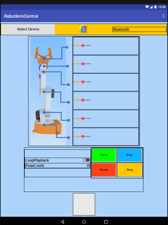
Building the Mobile App with MIT App Inventor for Bluetooth Robotic Arm Control
On the app side, the RobotArmControl is an Android app built in MIT App Inventor. It provides an intuitive touch interface for controlling all six joints of the DIY 6-DOF robotic arm wirelessly over Bluetooth. In addition, the app has six sliders (one per servo), buttons for saving, playing, stopping, and resetting poses, and a toggle for loop playback.
Key Features of the DIY 6-DOF Robotic Arm App
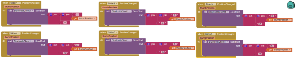
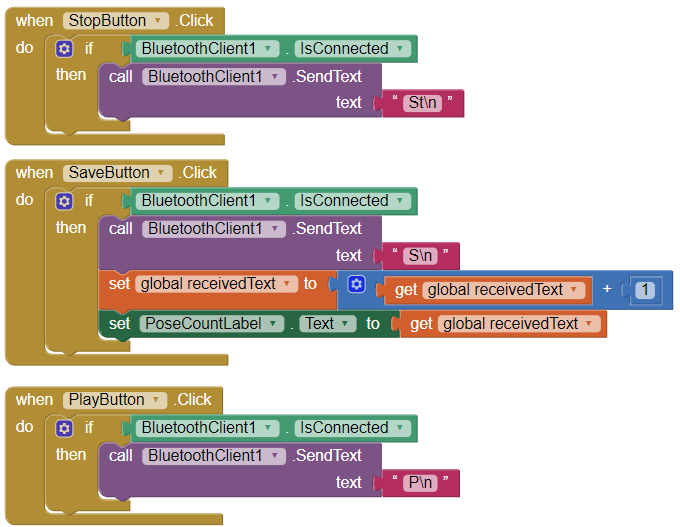
For real-time control, the app uses six sliders mapped to joints 0 through 5. When you move a slider, it sends a command like “2,90” that tells the Arduino to move servo 2 to 90 degrees. For example, the Save button sends “S” to store the current arm position. Similarly, Play sends “P” to replay all saved poses. Then, Stop sends “St” to halt playback. Finally, Reset sends “R” to clear all stored poses. The Loop switch sends “LoopON” or “LoopOFF” for continuous playback.
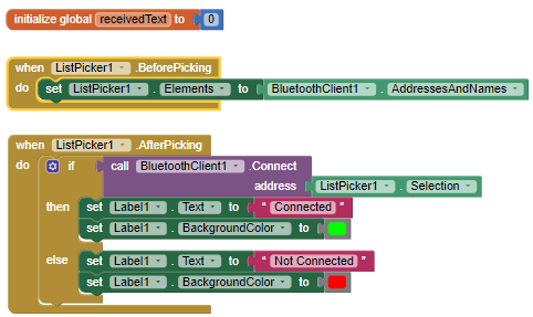
MIT App Inventor Blocks: Step-by-Step Explanation
The app logic uses with visual blocks in MIT App Inventor. First, the global initialization block creates a variable called receivedText (set to 0) that stores incoming data from the Arduino. Then, the ListPicker BeforePicking block fills the Bluetooth device list so you can pick the HC-05. Once you select a device, the AfterPicking block opens the Bluetooth serial connection.
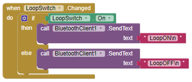
Each slider’s PositionChanged block formats the servo index and angle into a string like “2,90” and sends it with BluetoothClient.SendText. In the same way, the Save, Play, Stop, and Reset buttons each send their single-character commands. Finally, the LoopSwitch.Changed block checks the switch state and sends “LoopON” or “LoopOFF” accordingly.
Calibrating and Testing Your DIY 6-DOF Robotic Arm
Once the hardware is assembled, code uploaded, and app installed, the last step is calibration. Start by installing the RobotArmControl APK on your Android device. Next, go to your phone’s Bluetooth settings and pair with the HC-05 using the default PIN 1234. Then open the app, tap the Bluetooth list picker, and pick the HC-05 from the paired devices.
Once connected, slowly move each slider to check that the right joint responds. If a joint moves the wrong way, either swap the slider’s min and max values in App Inventor, or flip the map() range in the Arduino code. After that, you should fine-tune the PWM range (150 to 600 in the code) for each servo. Some servos need slightly different min and max values to avoid buzzing at the end stops. Also, test the arm under load by picking up small objects with the gripper. This confirms that each joint has enough torque.
To test the pose system, move the arm to a position and tap Save. Do this for several positions. Then tap Play to watch the arm replay the whole sequence. Also turn on Loop mode and check that the arm keeps cycling through all poses until you tap Stop.
Future Improvements for the DIY 6-DOF Robotic Arm
From here, this Bluetooth-controlled robotic arm is a good starting point for upgrades. For instance, you could add inverse kinematics so the arm moves to X-Y-Z coordinates instead of individual joint angles. Alternatively, adding a gyroscope or accelerometer would let you control the arm with phone tilts. Or you could replace the HC-05 with an ESP32 for Wi-Fi control through a web dashboard or home automation integration.
On the software side, you could also move pose storage to EEPROM so saved sequences survive a power cycle. In addition, you could add variable speed per joint, or build a teach-and-playback mode where you physically move the arm and it records the positions. Doing so would bring the project closer to how industrial robots work. For more project ideas, check out our mobile robot arm project (OmObiArm) that combines this arm with a mobile rover base.
Download Files for the DIY 6-DOF Robotic Arm Project
As mentioned, all project files are on our GitHub repository. The download includes the Arduino sketch (.ino), all STL files, the wiring diagram, and the MIT App Inventor project file (.aia) plus the compiled APK. The STL files are also available on Cults3D and in our OmArTronics Shop.
Download Arduino Code, STL Files, Wiring Diagram, and Mobile App from GitHub
Frequently Asked Questions (FAQ)
Here are answers to the most common questions about building and troubleshooting this DIY 6-DOF robotic arm with Bluetooth control.
Common questions about the DIY 6-DOF robotic arm
6-DOF means six degrees of freedom: five rotational joints for positioning plus one gripper joint.
Yes. Yes, the Mega uses the same code. The only difference is that I2C pins are 20 (SDA) and 21 (SCL) instead of A4 and A5.
Jitter usually means the PWM value hits the servo’s end stop. Adjust the map() range and check your power supply current.
The HC-05 uses classic Bluetooth, which iOS does not support. To use an iPhone, replace the HC-05 with an HM-10 (BLE) module and rebuild the app on a BLE platform.
Use PLA with 0.2 mm layer height and 40% infill for structural parts. Gripper gears can use 20%. Level your bed and add a brim for parts with small contact areas.
The code stores up to 10 poses in RAM by default. You can increase maxConfigurations, but the Uno only has 2 KB of SRAM. For persistent storage, save to EEPROM.
The HC-05 runs at 3.3 V logic. The Arduino sends 5 V, which can damage the HC-05 RX pin. A voltage divider with 1k and 2k resistors drops the signal to about 3.3 V.
Yes. Yes, the PCA9685 has 16 channels, so you can add up to 10 more servos. Just update numServos and servoChannels in the code.
With the standard STL files, the arm reaches about 40 cm from the base when fully extended. You can increase reach by lengthening the links in the CAD model.
Check the HC-05 LED (rapid blink = not paired). Verify baud rate (9600) and TX/RX wiring. If the app cannot find the module, re-pair in Bluetooth settings.
DIY 6-DOF Robotic Arm: Conclusion and Next Projects
Congratulations! You now have a fully functional DIY 6-DOF robotic arm with wireless Bluetooth smartphone control. Along the way, this project touches on the main areas of mechatronics: CAD design in Inventor, 3D printing, circuit design with I2C and Bluetooth serial, Arduino programming, and mobile app development with MIT App Inventor.
Best of all, the pose save-and-playback system turns this arm into a programmable robot that repeats movement sequences on its own. For instance, you can use it for automated pick-and-place, sorting, or even simple drawing tasks.
Where you take it from here is up to you. You could add computer vision with a camera module, implement inverse kinematics for Cartesian control, mount the arm on a mobile rover, or hook it up to a Raspberry Pi for machine learning. Whatever direction you take, this six-axis platform gives you a rock-solid foundation for deeper exploration into robotics and automation.
If you enjoyed this build, check out our other robotics tutorials: the line-following robot, the servo motor joystick controller, and the OmObiArm mobile robot arm.
Download the 3D Print Files (STL)
All 3D-printable STL files for this project are available for download. You can get them from our shop or browse them on Cults3D:
- OmArTronics Shop: Download project files from OmArTronics — Get the complete project package including STL files, wiring diagrams, and source code delivered to your email.
- Cults3D: View on Cults3D — Browse and download the 3D model files on Cults3D.
I bought the model but it doesn’t have the bearing measurement valueReport
Thanks for your comment, Fernando! Please add a ball bearing 6806ZZ with dimensions 30*42*7.
Hello,
Can you tell me where are the parts list, to can to buy the parts,I have your stl’s to Cults
Thank you
Antonio Mayor
I live near Barcelona
Hi, interesting project also to do with a teenager. Regarding the servo MG996R, it exists in 2 configurations : either 180° or 360°. What you recommend?
Best regards,
Emmanuel
Hi Emmanuel, thank you for your kind words! I recommend using the 180° version of the MG996R servo for this project. This is because the 180° servo allows precise control of the angle, which is essential for positioning and movement in robotic arms or similar applications. The 360° servo is designed for continuous rotation and is better suited for tasks like driving wheels, where angle control is not required. Best regards, OmArTronics.
sir i did the same connection but it is not working ,please tell me how much
current give the pca9685 servo controller
The PCA9685 servo controller itself draws very little current, typically less than 10mA. However, the total current needed depends on the servos you are using. Each MG996R servo, for example, can draw up to 2A (max 2,5 A) under load. Make sure your power supply can provide enough current for all connected servos, considering their combined maximum draw.
please sir reply it fast as soon as possible
hey, im trying to make it work but keep getting error 507. and not able to connect the app and the robot . how do I make it work ?
Hello, how can I find these bolts & screws in one place? Is there an online shopping site where they are all available on the internet?
for the 6 motors working how much power is needed thatnis voltage and amphere and which adapter you have used for this
I’m using six servos powered through a PCA9685 driver with an external 6 V power supply.
Each servo typically draws 300–600 mA depending on the load, so for six servos you should plan around 3–5 A total current.
I use a Hanmatek HM305P adjustable power supply, but any 5 V–6 V adapter rated for at least 5 A will work fine.
The Arduino itself is powered separately via USB.
hi, i hope you are well, i had a question about the screws, so what typr of screws are needed for the assmbling pat, and i blives so that iwoud get screw for servos with them, so could you please tell me the screw that needed and the quantity for the assmbling parts.