

Quick summary
Build an advanced autonomous robot car Arduino Mega project that avoids obstacles on its own using four HC-SR04 ultrasonic sensors and that you can steer from your phone over Bluetooth. This project uses an Arduino Mega and an Adafruit Motor Shield, with a 3D-printed chassis, and the ability to switch between autonomous and manual control.
In this tutorial, you will build an advanced autonomous robot car Arduino Mega project that can do two things: drive itself around obstacles using ultrasonic sensors, and respond to Bluetooth commands from your phone. The hardware side uses an HC-05 Bluetooth module, four HC-SR04 ultrasonic sensors, and an Adafruit Motor Shield. On the software side, you will write an Arduino sketch and build an Android control app with MIT App Inventor. I will walk you through the chassis assembly, wiring, code, and the app.
This project is an extension of our previous tutorial Building a Bluetooth-Controlled Robot Car with Arduino, HC-05, and Adafruit Motor Shield. It adds autonomous navigation using four ultrasonic sensors for obstacle detection in all four directions. For more on DC motor control with a motor shield, see our L298N Motor Driver and Arduino Motor Shield guide, and for ultrasonic sensor basics, check our Arduino Ultrasonic Distance Sensor tutorial.
What you will learn
By the end of this tutorial, you will know how to:
- Combine Bluetooth manual control and autonomous obstacle avoidance in a single Arduino sketch
- Use four HC-SR04 ultrasonic sensors to detect obstacles on all sides of the robot
- Drive four DC motors through the Adafruit Motor Shield V1 for differential steering
- Read Bluetooth commands and sensor data on the Arduino Mega to control movement
- Build a custom Android app in MIT App Inventor that switches between manual and autonomous modes
- Test, tune, and troubleshoot the robot so it runs reliably
How the robot works
Before we start building, here is a quick look at what each part of this advanced autonomous robot car Arduino Mega build does, so the build steps and wiring make more sense later:
Arduino Mega is the main controller. It runs the control loop, reads sensor data, processes Bluetooth commands, and sends signals to the motors. We use the Mega (instead of an Uno) because it has extra digital pins (pins 22–29 for the four ultrasonic sensors) and a hardware serial port on pins 0/1 for the HC-05.
Communication and control flow
HC-05 Bluetooth Module plugs into the Arduino Mega’s hardware serial port (TX on pin 1, RX on pin 0) and receives single-character commands from the Android app. The commands are: F (forward), B (backward), L (left), R (right), S (stop), and A (autonomous mode).
Adafruit Motor Shield V1 sits on top of the Arduino Mega and uses its own driver ICs to control up to four DC motors. Motors M1/M2 drive the left wheels, and M3/M4 drive the right wheels. The shield also handles the high-current motor signals so the Arduino pins are not overloaded. For a deeper look at motor shield usage, see our motor driver tutorial.
Four HC-SR04 Ultrasonic Sensors sit on the front, back, left, and right of the chassis. Each sensor measures the distance to the nearest obstacle by sending an ultrasonic pulse and timing the echo return. In autonomous mode, the Arduino reads all four sensors and decides whether to go forward, turn, or reverse. Learn more about how ultrasonic sensors work in our HC-SR04 tutorial.
Operating modes
Manual Bluetooth Mode: When the user presses a direction button in the Android app, the app sends a character command over Bluetooth. The Arduino reads the command and drives the motors accordingly. Releasing the button sends S (stop).
Autonomous Mode: When the user toggles the mode switch to Autonomous, the app sends A. The Arduino then enters a continuous loop that reads all four sensors. If nothing is within 20 cm in front, the robot drives forward at a speed proportional to the front distance. When the front path is blocked, it compares left and right distances and turns toward whichever side has more room. If both sides are also blocked, it reverses while scanning for an opening. Any manual Bluetooth command immediately exits autonomous mode.
Components needed for the autonomous robot car Arduino Mega
Here is the full parts list. Gather everything before you start building.
| Component | Qty | Required | Purpose | Notes |
|---|---|---|---|---|
| Arduino Mega 2560 | 1 | Yes | Main controller — runs the sketch and reads sensors | Mega is needed for extra digital pins (22–29) and hardware serial |
| Adafruit Motor Shield V1.2 | 1 | Yes | Drives four DC motors via M1–M4 terminals | Stacks directly on the Arduino Mega headers |
| HC-05 Bluetooth Module | 1 | Yes | Wireless communication with the Android app | Connects to Serial (pins 0/1); default pairing PIN is 1234 |
| HC-SR04 Ultrasonic Sensor | 4 | Yes | Front, back, left, and right obstacle detection | Requires two pins each (Trig + Echo) |
| DC Motor with Gearbox | 4 | Yes | Drives the four wheels | Standard 3–6 V geared DC motors |
| Plexiglas Sheet | 1 | Yes | Chassis base plate | Cut to your desired dimensions |
| 3D-Printed Frame, Motor Mounts, and Arduino Holder | 1 set | Yes | Secures motors and Arduino to chassis | Custom-designed or adapted from STL files |
| Jumper Wires | Assorted | Yes | All signal and power connections | M/M and M/F types |
| Battery Pack | 1 | Yes | Powers motors and Arduino | 6–12 V recommended; use the motor shield power terminals |
| Android Smartphone | 1 | Yes | Runs the MIT App Inventor control app | Bluetooth-capable Android device |
| Wheels | 4 | Yes | Attaches to gearbox motor shafts | Standard 65 mm robot car wheels |
| Screws, Nuts, Standoffs | Assorted | Yes | Mechanical assembly | M3 hardware recommended |
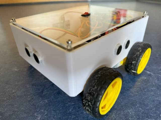
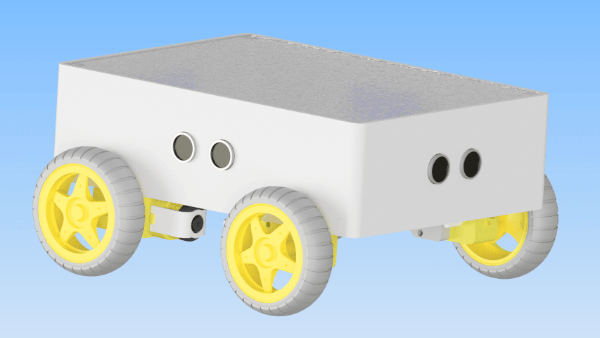
Step 1: Building the chassis for your robot car
To start building your advanced autonomous robot car Arduino Mega, make the chassis from a Plexiglas sheet. This is the base where all the other components will sit. For an introduction to 3D printing for robotics, see our 3D Printing beginner guide.
- Cut the Plexiglas: First, measure and cut the Plexiglas sheet to your desired dimensions for the chassis.
- 3D-Print the Frame and Motor Mounts: Design and print the frame and motor mounts that hold the four DC motors to the chassis. Position the mounts so the motors are symmetrical on both sides.
- 3D-Print the Arduino Holder: Design and print a holder for the Arduino Mega. Leave enough clearance for the Motor Shield that sits on top.
Step 2: Mounting the motors
Next, mount the four DC motors that will drive the robot car.
- Attach the Motors: Use screws and nuts to secure each DC motor to its 3D-printed motor mount.
- Mount the Motors on the Chassis: Attach the motor mounts to the Plexiglas chassis using screws and nuts. Ensure the left pair (M1, M2) and right pair (M3, M4) are aligned for straight driving.
Step 3: Mounting the Arduino Mega and motor shield
After mounting the motors, secure the Arduino Mega and the Adafruit Motor Shield on the chassis.
- Attach the Arduino Holder: Secure the 3D-printed Arduino holder to the chassis using screws.
- Mount the Arduino Mega: Then, place the Arduino Mega in the holder and secure it with screws. The Mega has the extra digital pins we need for four ultrasonic sensors.
- Attach the Motor Shield: Finally, place the Adafruit Motor Shield onto the Arduino Mega, ensuring all header pins are properly aligned. Press down firmly but carefully.
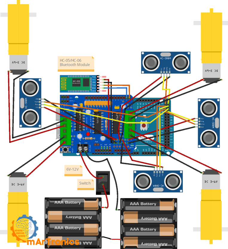
Step 4: Wiring the components
With the hardware assembled, it is time to wire everything up. Follow the tables below carefully. If you are new to Bluetooth modules, our HC-05/HC-06 Bluetooth Module Complete Tutorial covers the basics in detail.
Motor connections
| Motor | Motor Shield Terminal | Side |
|---|---|---|
| Left Front Motor | M1 | Left |
| Left Rear Motor | M2 | Left |
| Right Front Motor | M3 | Right |
| Right Rear Motor | M4 | Right |
HC-05 Bluetooth module connections
| HC-05 Pin | Arduino Mega Pin | Notes |
|---|---|---|
| VCC | 5 V | Power supply for the module |
| GND | GND | Common ground |
| TXD | RX (Pin 0) | HC-05 transmit → Arduino receive |
| RXD | TX (Pin 1) | Arduino transmit → HC-05 receive |
Important note about Serial pins 0/1: Because the HC-05 is connected to the Arduino Mega’s hardware Serial (pins 0 and 1). You need to disconnect the HC-05 TX/RX wires before uploading a new sketch, because the USB connection also uses Serial on the Mega. Once the upload finishes, reconnect the wires. Alternatively, you can use Serial1 (pins 18/19) on the Mega and change Serial.begin() to Serial1.begin() in the code to avoid this conflict.
Ultrasonic sensor connections
| Sensor | Position | Trig Pin | Echo Pin |
|---|---|---|---|
| Sensor_F | Front | Pin 23 | Pin 22 |
| Sensor_B | Back | Pin 25 | Pin 24 |
| Sensor_L | Left | Pin 27 | Pin 26 |
| Sensor_R | Right | Pin 29 | Pin 28 |
Each HC-SR04 sensor also needs a VCC (5 V) and GND connection. For more on how ultrasonic distance measurement works, see our Arduino Ultrasonic Distance Sensor: HC-SR04 Tutorial.
Power connections
Connect the battery pack’s positive and negative terminals to the power input on the Adafruit Motor Shield. The shield has its own power input for the motors. Make sure the common ground between the battery, motor shield, and Arduino is connected properly. A 6–12 V battery pack rated for at least 1–2 A works well here, since you are running four motors at once.
Step 5: Programming the Arduino for autonomous and Bluetooth control
Now for the code. The Arduino sketch for this advanced autonomous robot car Arduino Mega project handles both manual Bluetooth commands and autonomous obstacle avoidance. If you are new to Arduino programming, start with our Arduino Programming Basics: Complete Beginner Guide before diving in. The full source code and app files are also available on the GitHub Repository: App and Code.
Full Arduino sketch
Here is the complete Arduino sketch. Copy it into the Arduino IDE, verify, and upload to your Arduino Mega. Remember to disconnect the HC-05 TX/RX wires before uploading.
/**
 * Author: Omar Draidrya
 * Date: 2024/07/20
 * This sketch controls an advanced autonomous and Bluetooth-controlled robot car using Arduino Mega,
 * four HC-SR04 ultrasonic sensors, HC-05 Bluetooth module, and Adafruit Motor Shield V1.
 * The robot supports manual Bluetooth control (Forward, Backward, Left, Right, Stop) and
 * autonomous obstacle-avoidance navigation with front, rear, left, and right distance sensing.
 */
#include <AFMotor.h>
// Motor setup
AF_DCMotor motor1(1);
AF_DCMotor motor2(2);
AF_DCMotor motor3(3);
AF_DCMotor motor4(4);
// Ultrasonic sensor pins
const int trigF = 23;
const int echoF = 22;
const int trigL = 27;
const int echoL = 26;
const int trigR = 29;
const int echoR = 28;
const int trigB = 25;
const int echoB = 24;
char command;
bool autonomousModeEnabled = false; // Variable to track autonomous mode
// Function prototypes
void handleCommand(char command);
void forward(int speed = 160);
void backward(int speed = 160);
void turnLeft(int speed = 160);
void turnRight(int speed = 160);
void stop();
void autonomousMode();
int getDistance(int trigPin, int echoPin);
void setup() {
  Serial.begin(9600);
  pinMode(trigF, OUTPUT);
  pinMode(echoF, INPUT);
  pinMode(trigL, OUTPUT);
  pinMode(echoL, INPUT);
  pinMode(trigR, OUTPUT);
  pinMode(echoR, INPUT);
  pinMode(trigB, OUTPUT);
  pinMode(echoB, INPUT);
}
void loop() {
  if (Serial.available() > 0) {
    command = Serial.read();
    handleCommand(command);
  }
  if (autonomousModeEnabled) {
    autonomousMode();
  }
}
void handleCommand(char command) {
  if (command == 'F') {
    forward();
    autonomousModeEnabled = false; // Disable autonomous mode
  } else if (command == 'B') {
    backward();
    autonomousModeEnabled = false; // Disable autonomous mode
  } else if (command == 'L') {
    turnLeft();
    autonomousModeEnabled = false; // Disable autonomous mode
  } else if (command == 'R') {
    turnRight();
    autonomousModeEnabled = false; // Disable autonomous mode
  } else if (command == 'S') {
    stop();
    autonomousModeEnabled = false; // Disable autonomous mode
  } else if (command == 'A') {
    autonomousModeEnabled = true; // Enable autonomous mode
  }
}
void forward(int speed) {
  motor1.setSpeed(speed);
  motor2.setSpeed(speed);
  motor3.setSpeed(speed);
  motor4.setSpeed(speed);
  motor1.run(FORWARD);
  motor2.run(FORWARD);
  motor3.run(FORWARD);
  motor4.run(FORWARD);
}
void backward(int speed) {
  motor1.setSpeed(speed);
  motor2.setSpeed(speed);
  motor3.setSpeed(speed);
  motor4.setSpeed(speed);
  motor1.run(BACKWARD);
  motor2.run(BACKWARD);
  motor3.run(BACKWARD);
  motor4.run(BACKWARD);
}
void turnLeft(int speed) {
  motor1.setSpeed(speed);
  motor2.setSpeed(speed);
  motor3.setSpeed(speed);
  motor4.setSpeed(speed);
  motor1.run(BACKWARD);
  motor2.run(BACKWARD);
  motor3.run(FORWARD);
  motor4.run(FORWARD);
}
void turnRight(int speed) {
  motor1.setSpeed(speed);
  motor2.setSpeed(speed);
  motor3.setSpeed(speed);
  motor4.setSpeed(speed);
  motor1.run(FORWARD);
  motor2.run(FORWARD);
  motor3.run(BACKWARD);
  motor4.run(BACKWARD);
}
void stop() {
  motor1.run(RELEASE);
  motor2.run(RELEASE);
  motor3.run(RELEASE);
  motor4.run(RELEASE);
}
void autonomousMode() {
  int distanceF = getDistance(trigF, echoF);
  int distanceL = getDistance(trigL, echoL);
  int distanceR = getDistance(trigR, echoR);
  int distanceB = getDistance(trigB, echoB);
  // Prüfen, ob ein Hindernis vorne ist
  if (distanceF < 20) {
    stop();
    delay(100); // Verzögerung, um sicherzustellen, dass der Roboter angehalten hat
    // Hindernisvermeidung
    if (distanceR > distanceL && distanceR > 20) {
      turnRight(180);
      delay(300);
    } else if (distanceL > distanceR && distanceL > 20) {
      turnLeft(180);
      delay(300);
    } else if (distanceB > 20) {
      backward(160);
      while (distanceB > 20) {
        distanceB = getDistance(trigB, echoB);
        distanceL = getDistance(trigL, echoL);
        distanceR = getDistance(trigR, echoR);
        if (distanceR > 20 || distanceL > 20) {
          stop();
          delay(100);
          if (distanceR > distanceL) {
            turnRight(180);
          } else {
            turnLeft(180);
          }
          delay(300);
          break;
        }
        delay(100);
      }
      stop();
    } else {
      stop();
    }
  } else {
    adjustDirection(distanceL, distanceR);
    forward(map(distanceF, 20, 160, 64, 160));
  }
}
void adjustDirection(int distanceL, int distanceR) {
  if (distanceL < 20) {
    turnRight(180);
    delay(100);
    forward(160);
  } else if (distanceR < 20) {
    turnLeft(180);
    delay(100);
    forward(160);
  }
}
int getDistance(int trigPin, int echoPin) {
  digitalWrite(trigPin, LOW);
  delayMicroseconds(2);
  digitalWrite(trigPin, HIGH);
  delayMicroseconds(10);
  digitalWrite(trigPin, LOW);
  long duration = pulseIn(echoPin, HIGH);
  int distance = duration * 0.034 / 2;
  return distance;
}
Detailed code walkthrough
Let me walk through the code section by section.
Code explanation: Library and motor setup
The sketch includes the AFMotor.h library from Adafruit, which provides convenient functions for controlling DC motors through the Motor Shield. Four motor objects (motor1 through motor4) are created corresponding to the M1–M4 terminals on the shield. M1/M2 control the left wheels and M3/M4 control the right wheels.
Code explanation: Ultrasonic sensor pin mapping
Next, eight pin constants define the Trig and Echo connections for the four HC-SR04 sensors: trigF/echoF (front, pins 23/22), trigB/echoB (back, pins 25/24), trigL/echoL (left, pins 27/26), and trigR/echoR (right, pins 29/28). The setup() function configures all Trig pins as OUTPUT and Echo pins as INPUT.
Code explanation: Bluetooth command handling
During each pass through the loop() function, the Arduino also checks Serial.available() for incoming Bluetooth data. When a character arrives, the handleCommand() function maps it to a movement function: F → forward, B → backward, L → turnLeft, R → turnRight, S → stop. Each manual command also sets autonomousModeEnabled = false to immediately exit autonomous navigation. The command A enables autonomous mode by setting autonomousModeEnabled = true.
Code explanation: Manual mode movement functions
The forward(), backward(), turnLeft(), and turnRight() functions each set the speed for all four motors and then run them in the appropriate direction. Turning works through differential drive: turnLeft() runs the left motors backward and right motors forward, while turnRight() does the opposite. The stop() function releases all motors using RELEASE. Each function accepts an optional speed parameter (default 160 out of 255).
Code explanation: Autonomous mode and front obstacle logic
The autonomousMode() function runs when autonomousModeEnabled is true. First, it reads distances from all four sensors. If the front distance is less than 20 cm, the robot stops and enters obstacle avoidance. Then, it compares left and right distances: if the right side is clearer and greater than 20 cm, it turns right; if the left side is clearer, it turns left. However, if both sides are blocked, it attempts to reverse.
Code explanation: Side correction logic
The adjustDirection() function runs when no front obstacle exists. It checks left and right distances: if the left side is under 20 cm (the robot is drifting toward a wall), it briefly turns right and resumes forward. The same logic applies on the other side. As a result, this keeps the robot roughly centered between obstacles.
Code explanation: Reverse and escape logic
In the worst case, when the front, left, and right are all blocked but the rear is clear (distance > 20 cm), the robot reverses. During this maneuver, it continuously scans the left and right sensors. As soon as either side opens up (distance > 20 cm), accordingly, it stops, turns toward the open side, and breaks out of the reverse loop. Otherwise, it stops after the rear also becomes blocked.
Code explanation: Distance measurement function
The getDistance() function triggers the ultrasonic pulse on the given Trig pin and measures the return time on the Echo pin using pulseIn(). It converts the duration to centimeters with distance = duration * 0.034 / 2. The Arduino calls this function for each of the four sensors whenever it needs a distance reading.
Code explanation: Speed mapping logic
When the path ahead is clear, the code maps the forward speed using map(distanceF, 20, 160, 64, 160). The robot moves slower when the front obstacle is close (just above 20 cm) and faster when the path is wide open (160+ cm). The minimum speed of 64 keeps the motors from stalling at very low PWM values.
Step 6: Building the Android app for Bluetooth control
For the Android app, we use MIT App Inventor to build a simple interface that sends commands to the HC-05 over Bluetooth. If you are new to Arduino programming concepts, our Arduino Programming Basics guide provides helpful background. For a deeper dive into HC-05/HC-06 setup and pairing, see our HC-05/HC-06 Bluetooth Module Complete Tutorial.
Setting up the project
- Register and Log In: Go to MIT App Inventor and log in with your Google account.
- Create a New Project: Click on “Start New Project” and name it “RobotCarControl”.
Required UI components
Design the user interface with these components:
- ListPicker1: Set the text to “Select Bluetooth Device”. This lets the user pick the paired HC-05 from a list of available Bluetooth devices.
- BluetoothClient1: Add this from the Connectivity palette. It is a non-visible component that handles the Bluetooth serial connection.
- Label1: A text label used to display the connection status (“Connected” or “Not Connected”). This label must exist in the UI because the blocks code references it.
- ButtonForward, ButtonBackward, ButtonLeft, ButtonRight: Four directional control buttons. Set their colors for visual clarity (for example, green for forward, red for backward).
- ModeSwitch: A Switch component that toggles between manual and autonomous modes. When toggled ON, it sends “A” to enable autonomous mode. When toggled OFF, it sends “M” which the Arduino sketch does not explicitly handle (any unrecognized command simply leaves manual mode active).
How the ListPicker Bluetooth connection works
When the user taps the ListPicker, the BeforePicking event populates the list with paired Bluetooth devices from BluetoothClient1.AddressesAndNames. After the user selects a device, the AfterPicking event tries to connect using BluetoothClient1.Connect. If the connection succeeds, Label1 shows “Connected”; otherwise it shows “Not Connected”.
How TouchDown / TouchUp commands work
Each directional button uses TouchDown to send the movement command (F, B, L, or R) when pressed, and TouchUp to send “S” (stop) when released. The robot moves as long as the button is held down and stops the moment you let go.
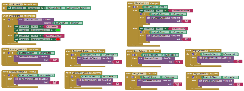
Programming the blocks
Add these blocks in MIT App Inventor’s Blocks editor to handle the Bluetooth connection and send commands:
when ListPicker1.BeforePicking
  set ListPicker1.Elements to BluetoothClient1.AddressesAndNames
when ListPicker1.AfterPicking
  if call BluetoothClient1.Connect address ListPicker1.Selection
    then set Label1.Text to "Connected"
    else set Label1.Text to "Not Connected"
when ButtonForward.TouchDown
  if BluetoothClient1.IsConnected
    call BluetoothClient1.SendText text "F"
when ButtonBackward.TouchDown
  if BluetoothClient1.IsConnected
    call BluetoothClient1.SendText text "B"
when ButtonLeft.TouchDown
  if BluetoothClient1.IsConnected
    call BluetoothClient1
.SendText text "L"
when ButtonRight.TouchDown
  if BluetoothClient1.IsConnected
    call BluetoothClient1.SendText text "R"
when ButtonForward.TouchUp
  if BluetoothClient1.IsConnected
    call BluetoothClient1.SendText text "S"
when ButtonBackward.TouchUp
  if BluetoothClient1.IsConnected
    call BluetoothClient1.SendText text "S"
when ButtonLeft.TouchUp
  if BluetoothClient1.IsConnected
    call BluetoothClient1.SendText text "S"
when ButtonRight.TouchUp
  if BluetoothClient1.IsConnected
    call BluetoothClient1.SendText text "S"
when ModeSwitch.Changed
  if ModeSwitch.On
    call BluetoothClient1.SendText text "A"
  else
    call BluetoothClient1.SendText text "M"
Step 7: Connecting and testing the robot
- Pair the Bluetooth Device: Turn on Bluetooth on your Android smartphone and pair with the HC-05 module. The default pairing password is usually 1234 or 0000.
- Connect via App: Open the RobotCarControl app, tap the ListPicker, and select your HC-05 device. If successful, Label1 should change to “Connected”.
- Test Manual Bluetooth Control: Press each directional button and check that the robot moves the right way. Release the button and confirm the robot stops.
- Test Autonomous Mode: Toggle the mode switch to Autonomous. Then, place an obstacle in front of the robot and observe whether it stops and turns to avoid it.
How to test and tune your autonomous robot car Arduino Mega
Getting this advanced autonomous robot car Arduino Mega build to behave reliably takes some tuning. Here is how I recommend approaching it:
- Test Bluetooth commands first: Before testing autonomous mode, verify that each manual command (F, B, L, R, S) produces the correct motor response. This confirms your wiring and code are correct.
- Verify motor direction: If a motor spins the wrong way, swap its two wires at the motor shield terminal. All four motors must agree on “forward.”
- Verify each ultrasonic sensor individually: Add temporary
Serial.println()statements to print each sensor’s distance reading to the Serial Monitor. Confirm that front, back, left, and right all read reasonable values and respond to objects placed in front of them. - Tune obstacle distance thresholds: The code uses 20 cm as the threshold. If your robot reacts too late (crashes) or too early (stops far from obstacles), adjust this value in the
autonomousMode()function. - Tune speed values: The default speed is 160 (out of 255). If your motors are too fast or too slow, adjust the default speed parameter and the
map()range. Heavier robots or weaker motors may need higher minimum speeds. - Tune turn timing: Turn duration is controlled by
delay(300)after turning commands. If the robot does not turn enough (or turns too far), increase or decrease this delay value. - Adapt for different chassis/motor combinations: Every chassis has different weight, friction, and motor torque. Expect to iterate on speed, delay, and threshold values until your specific build runs smoothly.
Troubleshooting your autonomous robot car Arduino Mega
If something is not working, check this table for common issues and fixes:
| Problem | Likely Cause | Solution |
|---|---|---|
| HC-05 pairs but robot does not move | App is not sending commands, or wiring is incorrect | Check that BluetoothClient1.IsConnected is true in the app. Verify motor shield wiring and battery power. |
| Upload fails with error on Serial | HC-05 TX/RX wires occupy pins 0/1 | Disconnect HC-05 TX and RX wires before uploading. Reconnect after upload completes. |
| Robot moves in the wrong direction | Motor wires are swapped | Swap the two wires for the affected motor at the shield terminal, or swap the motor object assignments in code. |
| Ultrasonic sensor gives unstable readings | Loose wiring, electrical noise, or sensor facing a soft/angled surface | Secure all jumper wires. Add a small delay between sensor readings. Test with a flat, hard surface. |
| Robot keeps stopping unexpectedly | Front sensor reads false short distances | Check for loose Trig/Echo wires. Ensure the sensor is mounted firmly and not vibrating. |
| Autonomous mode gets stuck in a corner | All four directions are blocked within 20 cm | This is a limitation of the simple algorithm. Try increasing the threshold or adding a random turn escape. |
| Motors are weak or inconsistent | Insufficient battery voltage or current | Use fresh batteries or a higher-capacity battery pack. Check for voltage drop under load. |
| Battery power is insufficient | Too many components drawing current | Use a separate battery for motors (via the shield power input) and power the Arduino via USB or a separate regulated supply. |
| Robot turns the wrong way in autonomous mode | Left/right sensors are swapped in wiring or code | Verify that Sensor_L is physically on the left and Sensor_R on the right. Check pin assignments match the physical layout. |
Frequently asked questions
No, unfortunately the Arduino Uno does not have enough digital pins to connect four ultrasonic sensors (which need 8 pins) plus the Motor Shield, which already uses several pins. The Arduino Mega provides pins 22–29 for the sensors and hardware serial on pins 0/1 for Bluetooth, which makes it the better board for this project.
The V1 shield uses the AFMotor.h library and directly drives motors through shift registers. The V2 uses I2C communication and the Adafruit_MotorShield library. However, this tutorial uses the V1. If you have a V2, you will need to change the library and motor initialization code accordingly.
Yes. The HC-06 works as a Bluetooth receiver (slave only) and can replace the HC-05 for this project since the robot only needs to receive commands. The wiring and code stay the same. See our HC-05/HC-06 Complete Tutorial for details on the differences.
In the autonomousMode() function, the threshold is set to 20 cm in conditions like if (distanceF < 20). For instance, increase this value to 30 if you want the robot to react earlier, or decrease it if the robot stops too far from obstacles.
Usually, uneven motor speeds, different wheel friction, or slight differences between the left and right motors can cause drifting. To fix this, try adjusting individual motor speeds in the forward() function, or add PID control for more precise straight-line driving.
Unfortunately, the HC-05 uses classic Bluetooth (SPP), which iOS does not natively support, to use an iPhone, replace the HC-05 with a BLE module (such as the HM-10) and build the app using a BLE-compatible platform.
A 6–12 V battery pack with at least 1–2 A capacity works well. For example, common options include 4×AA alkaline batteries (6 V), a 7.4 V 2S LiPo battery, or a 9 V battery (though 9 V batteries have limited current). Connect the battery to the motor shield’s dedicated power input terminals.
Not necessarily. 3D-printed mounts and holders provide a clean and precise fit, but you can also use other materials. Laser-cut acrylic, hand-cut plywood, or even a commercial robot car chassis kit can work. What matters is that the motors and sensors are mounted securely. For 3D printing tips, see our Introduction to 3D Printing guide.
In this project, we use four sensors for full 360-degree coverage (front, back, left, right). For basic forward obstacle avoidance, a single front sensor is sufficient, however, side and rear sensors greatly improve the robot’s ability to navigate tight spaces and reverse safely.
Yes. Common upgrades include adding a servo-mounted ultrasonic sensor for scanning, integrating IR line-following sensors, adding an OLED display for status readouts, or implementing PID speed control. Check the Next Projects section below for ideas.
Resources and next projects
Now that your advanced autonomous robot car Arduino Mega project is running, here are some related tutorials and upgrade ideas if you want to keep going:
Related OmArTronics tutorials
- Building a Bluetooth-Controlled Robot Car with Arduino, HC-05, and Adafruit Motor Shield — the foundational project this tutorial builds upon
- Arduino and HC-05/HC-06 Bluetooth Module Complete Tutorial — deep dive into Bluetooth setup and communication
- Arduino Ultrasonic Distance Sensor: HC-SR04 Tutorial — learn how ultrasonic distance measurement works
- L298N Motor Driver with Arduino: DC Motor Control Guide — motor driver fundamentals
- Arduino Programming Basics: Complete Beginner Guide — start here if you are new to Arduino
- Arduino Servo Control Guide: SG90, PWM, and PCA9685 — useful if you want to add a servo scanner to your robot
Upgrade ideas
- Add a servo-mounted front ultrasonic sensor for 180-degree scanning (see our Arduino Radar with HC-SR04 and Servo Motor guide)
- Integrate line-following sensors for track-based navigation (see our Line Following Robot with KY-033 Sensors tutorial)
- Build a DIY 6-DOF Robotic Arm with Bluetooth Control as your next robotics challenge
- Add an OLED or LCD display to show sensor readings and connection status in real time
- Implement PID motor control for precise speed matching and straight-line driving (more advanced)
Conclusion
If you have followed along, you now have a working advanced autonomous robot car Arduino Mega that can dodge obstacles on its own and respond to Bluetooth commands from your phone. In the process, you wired up the Adafruit Motor Shield and four ultrasonic sensors, wrote the Arduino sketch for obstacle avoidance, paired an HC-05 Bluetooth module, and built an Android app in MIT App Inventor to control it all.
This advanced autonomous robot car Arduino Mega project is a solid starting point if you want to get deeper into mobile robotics. You could add more sensors, try a smarter navigation algorithm, or even bolt on a camera for vision-based control. Explore our other OmArTronics robotics tutorials for your next build, and drop a comment below if you run into any issues.
Download the 3D print files (STL)
All 3D-printable STL files for this project are available for download. You can get them from our shop or browse them on Cults3D:
- OmArTronics Shop: Download project files from OmArTronics — Get the complete project package including STL files, wiring diagrams, and source code delivered to your email.
- Cults3D: View on Cults3D — Browse and download the 3D model files on Cults3D.