


Quick summary
This tutorial covers the HC-05 and HC-06 Bluetooth modules with Arduino, so you can get started quickly. In particular, I go over the differences between master and slave modes, wiring, AT command configuration, and how to control an LED from your phone. I also cover hardware UART vs. SoftwareSerial.
Want to control an LED or a 230V lamp from your phone using Arduino and Bluetooth? In this tutorial, I walk through the HC-05 and HC-06 Bluetooth modules. We will cover wiring, code, and also how to build a simple Android app with MIT App Inventor. The tutorial has two projects, so you can follow along regardless of your experience level.
First, the LED control project is the simpler one. Then the second project extends that to a relay based 230V lamp control system. Both use the same HC-05 or HC-06 module and the same Android app, so you only need to learn the basics once. If you are new to Arduino, consider starting with our Arduino programming basics guide first.
What you will learn
By the end, you will know how to:
- First, understand the difference between HC-05 and HC-06 Bluetooth modules and when to use each one
- Understand how Bluetooth serial communication works with Arduino
- Then, wire the HC-05 or HC-06 module safely to an Arduino board
- Write Arduino code to receive Bluetooth commands and control outputs
- Control an LED wirelessly from your Android phone (beginner project)
- Build a simple Bluetooth control app using MIT App Inventor
- Extend the setup to a relay based 230V lamp control project (advanced extension)
- Finally, troubleshoot common Bluetooth communication problems
HC-05 vs. HC-06: key differences and which one to choose
The HC-05 and HC-06 are two of the most common Bluetooth modules you will see in Arduino projects. Both use the Bluetooth v2.0+EDR specification and also communicate through a serial interface. However, they differ in one critical way: the HC-05 can operate as both a master and a slave device, while the HC-06 works only as a slave. So the HC-05 can start a connection to another Bluetooth device (like a second Arduino), whereas the HC-06 just waits for something to connect to it.
For most beginner projects, including both projects in this tutorial, the HC-06 works perfectly well since your smartphone acts as the master and the module acts as the slave. If you plan to build projects where two Arduinos communicate with each other (for example, a Bluetooth-controlled robot car receiving commands from another Arduino), you should choose the HC-05 instead.
Technical comparison table
| Feature | HC-05 | HC-06 |
|---|---|---|
| Role | Master & Slave | Slave only |
| Bluetooth Protocol | v2.0+EDR | v2.0+EDR |
| Frequency | 2.4 GHz ISM Band | 2.4 GHz ISM Band |
| Modulation | GFSK | GFSK |
| Transmit Power | 4 dBm, Class 2 | 4 dBm, Class 2 |
| Sensitivity | -84 dBm at 0.1% BER | -84 dBm at 0.1% BER |
| Max Data Rate | 2.1 Mbps (async) / 1 Mbps (sync) | 2.1 Mbps (async) |
| Supported Profiles | Serial Port (Master & Slave) | Serial Port (Slave only) |
| Operating Voltage | 3.3–5 V DC | 3.3–5 V DC |
| Operating Current | ~50 mA | ~50 mA |
| Operating Temperature | -5 °C to +45 °C | -5 °C to +45 °C |
| Default Baud Rate | 38400 (AT mode: 38400) | 9600 |
| Baud Rate Range | Configurable: 2400–1382400 | Fixed at 9600 (some versions configurable) |
| Default Password | 1234 | 1234 |
Which module should you choose?
- Choose HC-06 if your project only needs to receive commands from a smartphone or computer. It is also simpler to set up and costs a bit less. In fact, most LED control, relay switching, and app controlled projects work fine with it.
- Choose HC-05 if you need master mode (for example, Arduino-to-Arduino communication), or if you want the flexibility to change baud rates and configure advanced AT commands. Instead, the HC-05 is the better choice for projects like a Bluetooth-controlled robotic arm or a mobile robot with an integrated arm.
How the Arduino Bluetooth control system works
This is how the communication works:
- First, serial communication on the Arduino: The Arduino uses its hardware serial pins (TX on pin 1, RX on pin 0) to send and receive data. The
Serial.begin()function sets the communication speed (baud rate), andSerial.read()receives incoming bytes. - Next, HC-05/HC-06 as a wireless serial bridge: The Bluetooth module connects to the Arduino’s serial pins and acts as a transparent wireless serial link. Anything your phone sends over Bluetooth arrives at the Arduino’s RX pin exactly as if it were sent through a USB cable.
- Then, the smartphone sends simple character commands: An Android app (built with MIT App Inventor) sends a single character, for example
'1'to turn something ON and'0'to turn it OFF, over the Bluetooth connection. - Finally, the Arduino interprets the command and switches an output: The Arduino reads the incoming character and uses a simple
if/elsestatement to decide whether to set a digital pin HIGH or LOW, thereby turning an LED or relay on or off.
The basic pattern is simple: the phone sends a character, then the module passes it over serial, and finally the Arduino reads it and acts. Once you get this, you can also extend it to motors, servos, displays, or whatever else you need. For a deeper look at Arduino board architecture, see our guide on what Arduino is and how it works.
Components needed
Here are the components organized by project, so you know what to buy. Everything in the “Core Components” table applies to both Part 1 (LED control) and also Part 2 (relay lamp control). Meanwhile, the additional components tables list items you only need for the advanced relay project.
Core components (both projects)
| Component | Quantity | Notes |
|---|---|---|
| HC-05 or HC-06 Bluetooth Module | 1 | Either module works for both projects |
| Arduino Board (Uno, Mega, Nano, etc.) | 1 | Any board with hardware serial pins |
| Breadboard | 1 | For prototyping connections |
| Jumper Wires (male-to-male) | Several | For connecting components |
| USB Cable (Type A to B) | 1 | For uploading code to Arduino |
| Android Smartphone | 1 | For running the Bluetooth control app |
Additional components for Part 1: LED control
| Component | Quantity | Notes |
|---|---|---|
| LED (any color) | 1 | Standard 5 mm through-hole LED |
| 220 Ω Resistor | 1 | Current-limiting resistor for the LED |
Additional components for Part 2: relay / 230V lamp control
| Component | Quantity | Notes |
|---|---|---|
| Relay Module (5V, single-channel) | 1 | Opto-isolated relay module recommended |
| Lamp or Appliance (230V / 110V) | 1 | Any mains powered load |
| Lamp Holder and Power Cable | 1 | For safe mains wiring |
Part 1: Bluetooth LED Control (Beginner Project)
In this first project, you will connect an HC-05 or HC-06 Bluetooth module to an Arduino and then control an LED from your smartphone. This is the simplest way to learn Arduino Bluetooth control, and it also gets you ready for the relay project in Part 2.
Circuit wiring for LED control
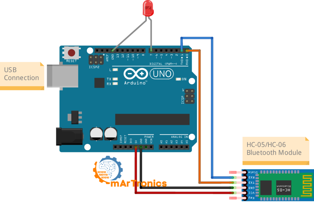
First, connect the HC-05/HC-06 module and LED to the Arduino as shown in the table below. Also pay attention to the TX/RX connections. The module’s TXD pin connects to the Arduino’s RX (pin 0), and the module’s RXD pin connects to the Arduino’s TX (pin 1). You should use a voltage divider on the RXD line because the module’s logic operates at 3.3V, while the Arduino outputs 5V on the TX pin.
| HC-05/HC-06 Pin | Arduino Pin | Notes |
|---|---|---|
| VCC | 5V | Power supply for the module |
| GND | GND | Common ground |
| TXD | RX (Pin 0) | Module transmit → Arduino receive |
| RXD | TX (Pin 1) | Use a voltage divider (1 kΩ + 2 kΩ) for 3.3V safety |
| LED Pin | Arduino Pin | Notes |
|---|---|---|
| Anode (long leg) | Pin 7 (through 220 Ω resistor) | Digital output pin |
| Cathode (short leg) | GND | Common ground |
Arduino code for Bluetooth LED control
Next, upload the following sketch to your Arduino. This code listens for incoming Bluetooth commands on the serial port and switches the LED on pin 7 on or off depending on the character received.
Important: Before uploading, always disconnect the Bluetooth module from pins 0 and 1. The Arduino uses the same serial pins for USB programming, so having the module connected can cause upload failures. Then, after the upload completes, reconnect the module.
/**
 * Author: Omar Draidrya
 * Date: 2024/06/07
 * Bluetooth LED Control -- HC-05 / HC-06 Arduino Tutorial
 * Receives '1' or '0' from a smartphone via Bluetooth
 * and turns an LED on or off.
 */

#define ledPin 7 // Pin for the LED

char state = 0; // Variable to store incoming data

void setup() {
  pinMode(ledPin, OUTPUT);      // Set the LED pin as output
  digitalWrite(ledPin, LOW);    // Initialize the LED state to OFF
  Serial.begin(9600);           // Start serial at 9600 baud
}

void loop() {
  if (Serial.available() > 0) {       // Check if data is available
    state = Serial.read();             // Read the incoming byte

    if (state == '0') {                // If '0' is received
      digitalWrite(ledPin, LOW);       // Turn LED OFF
      Serial.println("LED: OFF");      // Send confirmation back
    } else if (state == '1') {         // If '1' is received
      digitalWrite(ledPin, HIGH);      // Turn LED ON
      Serial.println("LED: ON");       // Send confirmation back
    }
  }
}
Code explanation
This sketch uses the Arduino’s hardware serial port to talk to the Bluetooth module. Here is what each part does:
#define ledPin 7: Assigns pin 7 as the LED output pin. You can change this to any digital pin.Serial.begin(9600): This starts serial communication at 9600 baud, so it must match the baud rate of your Bluetooth module. The HC-06 defaults to 9600 baud. If you are using an HC-05, you may need to set it to 9600 using AT commands, or change this line toSerial.begin(38400)to match the HC-05 default of 38400.Serial.available(): This returns the number of bytes waiting in the serial buffer. When the phone sends a character over Bluetooth, then this becomes greater than 0.Serial.read(): Reads one byte from the serial buffer and stores it in thestatevariable.if (state == '1'): Compares the received character to ‘1’. If it matches, then the LED turns ON usingdigitalWrite(ledPin, HIGH). If ‘0’ arrives instead, the LED turns OFF.Serial.println(): This also sends a confirmation message back to the phone, which you can display in the app for feedback.
Baud rate note: For reference, the HC-06 module typically defaults to 9600 baud, while the HC-05 defaults to 38400 baud in communication mode. The code above uses 9600 for compatibility with the HC-06. If you are using an HC-05 and have not changed its baud rate, replace Serial.begin(9600) with Serial.begin(38400). Therefore, the baud rate in your code must always match what your module uses, or communication will fail.
Building the Bluetooth control app with MIT App Inventor
To send commands to the Arduino from your phone, you need a simple Android app. In this section, you will build one using MIT App Inventor, a free visual programming platform. The same app works for both the LED project and the relay project. The Arduino code determines what happens when it receives ‘1’ or ‘0’, not the app.
Step 1: Register and create a project
- First, go to MIT App Inventor and log in with your Google account.
- Then, click “Start New Project” and name it “BluetoothControl”.
Step 2: Design the user interface
In the Designer view, then add these components to your screen:
- First, a Label. Set its text to “Bluetooth Control”. This serves as the app title.
- Next, a ListPicker. Set its text to “Select Bluetooth Device” and rename it to “ListPicker_Bluetooth”. This will show available paired Bluetooth devices.
- Then, add two Buttons:
- Button 1: Name it “Button_ON”, set text to “Turn ON”.
- Button 2: Name it “Button_OFF”, set text to “Turn OFF”.
- Finally, add a BluetoothClient component from the Connectivity palette (this is a non-visible component that handles the Bluetooth connection).
Step 3: Program the blocks
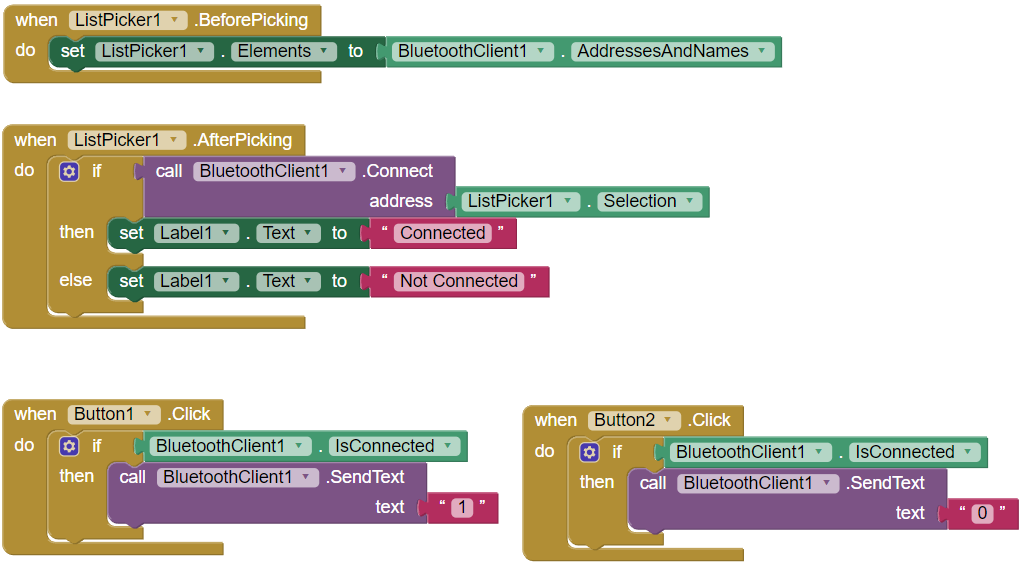
Next, switch to the Blocks editor and then create the following logic:
when ListPicker1.BeforePicking
  set ListPicker1.Elements to BluetoothClient1.AddressesAndNames

when ListPicker1.AfterPicking
  if call BluetoothClient1.Connect address ListPicker1.Selection
    then set Label1.Text to "Connected"
    else set Label1.Text to "Not Connected"

when Button1.Click
  if BluetoothClient1.IsConnected
    call BluetoothClient1.SendText text "1"

when Button2.Click
  if BluetoothClient1.IsConnected
    call BluetoothClient1.SendText text "0"
Here is how these blocks work: First, before the ListPicker opens, it loads all paired Bluetooth device names and addresses. Then, when you select a device, the app attempts to connect. If the connection succeeds, the label updates to “Connected.” Finally, the two buttons send the characters “1” and “0” over Bluetooth when pressed, and the Arduino receives these characters and acts on them.

Step 4: Build and install the app
Finally, in MIT App Inventor, go to Build → App (provide QR code for .apk). After that, scan the QR code with your phone to download and install the app. Also, you may need to enable “Install from unknown sources” in your Android settings.
Connecting your smartphone to the HC-05/HC-06 module
This connection process is the same for both projects. After you do it once, you can reuse the same pairing for any future Bluetooth Arduino project.
Step 1: Pair the Bluetooth module
- First, power your Arduino (via USB or external power). At that point, the HC-05/HC-06 module’s LED should start blinking rapidly, indicating it is in pairing mode.
- Then, on your Android phone, go to Settings → Bluetooth and enable Bluetooth.
- Next, scan for devices. You should see “HC-05” or “HC-06” in the available devices list.
- Then tap the device name to pair. When prompted for a password, enter 1234 (this is the default for both modules).
- After pairing, the module will appear under “Paired devices.” The module’s LED may change to a slower blink or stay solid, depending on the model.
Step 2: Connect via the app
- First, open the Bluetooth control app you built with MIT App Inventor.
- Tap “Select Bluetooth Device”. A list of paired devices will appear.
- Then, then select the HC-05 or HC-06 from the list. If successful, the label should change to “Connected.”
- Press “Turn ON” to send ‘1’ to the Arduino (LED or relay turns on). Press “Turn OFF” to send ‘0’ (LED or relay turns off).
If the app cannot find the module, then first make sure the module has power and its LED blinks rapidly. Also, confirm that you already paired it in the phone’s Bluetooth settings. Because the app’s ListPicker only shows previously paired devices, new ones will not appear.
Part 2: Bluetooth Relay and 230V Lamp Control (Advanced Extension)
Since you have successfully controlled an LED over Bluetooth, you can now extend the same concept to switch a mains powered lamp using a relay module. In short, the relay is an electrically controlled switch. The Arduino activates the relay, and the relay then connects or disconnects the 230V (or 110V) lamp circuit.
⚠ Safety Warning: This project involves mains voltage AC power (230V or 110V), which can cause serious injury or death. If you do not have experience with mains wiring, then do not attempt this project. Instead, work with a qualified electrician or test with a low voltage load (such as a 12V LED strip powered through the relay) before connecting to mains power. Always ensure all high voltage connections stay properly insulated, and never touch exposed wires when the circuit has power.
Tip for beginners: As an alternative, you can also safely test the relay project without mains voltage by connecting a low voltage DC load (such as a 5V buzzer or a battery powered LED) to the relay’s normally open (NO) and common (COM) terminals. This way, you can then verify the relay clicks and the circuit works before introducing any dangerous voltages.
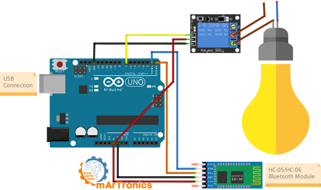
Circuit wiring for relay lamp control
Note that the Bluetooth module connections remain exactly the same as in Part 1, so you only need to change the output wiring. Instead, pin 7 now drives the relay module instead of an LED.
| Relay Module Pin | Arduino Pin | Notes |
|---|---|---|
| VCC | 5V | Power for the relay module |
| GND | GND | Common ground |
| IN (Signal) | Pin 7 | Control signal from Arduino |
| Lamp Connection | Relay Terminal | Notes |
|---|---|---|
| Lamp wire 1 | NO (Normally Open) | Connects when relay is activated |
| Live wire (L) from mains | COM (Common) | Incoming mains live wire |
| Neutral wire (N) from mains | Directly to lamp | Neutral bypasses the relay |
Arduino code for Bluetooth relay control
As you will see, the relay control code looks very similar to the LED code. The main difference is that pin 7 now drives the relay’s input signal, and also the baud rate is 38400 to match the HC-05 default. If you use an HC-06 instead, then change Serial.begin(38400) to Serial.begin(9600).
/**
 * Author: Omar Draidrya
 * Date: 2024/06/07
 * Bluetooth Relay/Lamp Control -- HC-05 / HC-06 Arduino Tutorial
 * Receives '1' or '0' from a smartphone via Bluetooth
 * and switches a relay (connected to a lamp) on or off.
 */

#define relayPin 7   // Pin connected to relay IN

int state = 0;       // Variable to store incoming data

void setup() {
  pinMode(relayPin, OUTPUT);       // Set relay pin as output
  digitalWrite(relayPin, LOW);     // Initialize relay to OFF
  Serial.begin(38400);             // HC-05 default baud rate
}

void loop() {
  if (Serial.available() > 0) {        // Check if data is available
    state = Serial.read();              // Read the incoming byte
  }

  if (state == '0') {
    digitalWrite(relayPin, LOW);        // Turn Relay OFF
    Serial.println("Lamp: OFF");        // Send confirmation back
    state = 0;                          // Reset state
  } else if (state == '1') {
    digitalWrite(relayPin, HIGH);       // Turn Relay ON
    Serial.println("Lamp: ON");         // Send confirmation back
    state = 0;                          // Reset state
  }
}
Code explanation
This sketch follows the same pattern as the LED sketch, with a few differences:
Serial.begin(38400): The baud rate is set to 38400, which is the HC-05’s default communication speed. If you are using an HC-06 (which defaults to 9600), change this toSerial.begin(9600).state = 0;after each action: The state variable resets after processing each command. As a result, the relay does not trigger repeatedly from the same command.- The relay module interprets a HIGH signal on pin 7 as “activate,” which then closes the relay switch and completes the lamp circuit. Similarly, a LOW signal deactivates the relay and turns the lamp off.
- The app stays the same. You do not need to build a new app. Since the same MIT App Inventor app from the previous section sends ‘1’ and ‘0’, and the Arduino code determines what those commands do.
After uploading the code (remember to disconnect the Bluetooth module from pins 0/1 first), then reconnect the module and use the same Bluetooth control app to test. If everything works, then the relay should click when you press “Turn ON” and release when you press “Turn OFF.”
Troubleshooting common Bluetooth issues
If your Bluetooth setup does not work as expected, then work through these common issues first:
| Problem | Likely Cause | Solution |
|---|---|---|
| Phone cannot find the HC-05/HC-06 module | Module not powered or not in pairing mode | Check that the module’s LED is blinking rapidly. Verify VCC and GND connections. Make sure Bluetooth is enabled on your phone. |
| Bluetooth pairs but the app does not control the Arduino | Baud rate mismatch between code and module | The Serial.begin() value in your code must match the module’s baud rate. HC-06 defaults to 9600; HC-05 defaults to 38400. |
| LED does not switch on or off | Wrong pin or missing resistor | Double-check that the LED anode is connected to pin 7 through a 220 Ω resistor, and the cathode goes to GND. Verify pin 7 in the code. |
| Relay clicks but lamp does not turn on | Incorrect mains wiring at the relay | Verify the live wire connects to COM, and the lamp wire connects to NO (Normally Open). Check the neutral wire goes directly to the lamp. |
| TX/RX wiring seems wrong or communication fails | TX and RX are swapped | Remember: the module’s TXD goes to the Arduino’s RX (pin 0), and the module’s RXD goes to the Arduino’s TX (pin 1). They cross over. |
Serial communication and app issues
| Problem | Likely Cause | Solution |
|---|---|---|
| No response from Arduino after uploading code | Bluetooth module was connected during upload | Disconnect the Bluetooth module from pins 0 and 1 before uploading. The USB serial and Bluetooth module share the same pins, causing conflicts. |
| App connects but commands have no effect | App is sending wrong characters | Verify that Button_ON sends the text “1” (not the number 1) and Button_OFF sends “0”. In the Arduino code, the comparison uses character literals (‘1’ and ‘0’). |
| Module LED stays solid (not blinking) | Module is in AT command mode or already connected | Power-cycle the module. If it enters AT mode on startup (HC-05 with KEY pin held HIGH), disconnect the KEY pin and restart. |
| App shows “Not Connected” after selecting the device | Module is already connected to another device, or pairing expired | Unpair and re-pair the module in your phone’s Bluetooth settings. Make sure no other phone or app is connected to the module. |
Frequently asked questions
Can I control more than one LED or relay with this setup?
Yes. You can expand the code to listen for more characters (such as ‘2’, ‘3’, ‘A’, ‘B’) and assign each one to a different pin. You would also add more buttons in the MIT App Inventor app, with each button sending a different character. This is the same approach used in projects like the Bluetooth-controlled robot car, where the app sends multiple motor commands as different characters.
Does this work with iPhone (iOS)?
No. The HC-05 and HC-06 use Bluetooth Classic (SPP profile), and iOS does not support this protocol. iPhones need Bluetooth Low Energy (BLE) modules such as the HM-10 or the ESP32’s built-in BLE. For Android phones, however, the HC-05 and HC-06 work without issues.
How far does the Bluetooth connection reach?
Both the HC-05 and HC-06 are Class 2 Bluetooth devices with a typical range of about 10 meters (33 feet) in open air. However, walls, furniture, and other obstacles will reduce the effective range.
Can I use SoftwareSerial instead of hardware serial pins 0 and 1?
Yes. The SoftwareSerial library lets you use other digital pins (for example, pins 10 and 11) as serial TX and RX. This avoids the upload conflict and also lets you use the Serial Monitor for debugging at the same time. SoftwareSerial works less reliably at higher baud rates though, so 9600 baud is your best bet when using it.
Is it safe to connect 230V mains to a relay controlled by Arduino?
A properly rated relay module can safely switch mains voltage. That said, wiring mains voltage circuits requires electrical knowledge and safety precautions. If you lack experience, test with a low voltage load first and consult a qualified electrician before working with mains power. Always make sure all high voltage connections are insulated and enclosed.
What is the difference between the HC-05 and HC-06?
The HC-05 can work as both a Bluetooth master and slave, meaning it can both start and accept connections. The HC-06 can only work as a slave, so it only accepts connections from a phone or computer. For projects where your phone controls an Arduino, though, either module works. For Arduino-to-Arduino Bluetooth communication, you need at least one HC-05 set as master.
Can I use this with other Arduino boards?
Yes. Since both modules communicate via serial (TX/RX), you can use any Arduino board with serial pins. On the Arduino Mega, you can also use Serial1, Serial2, or Serial3, which avoids the upload conflict on pins 0 and 1. On the Nano, the wiring stays the same as the Uno.
What is the default pairing password?
The default pairing password (PIN) for both the HC-05 and HC-06 is 1234. Some HC-06 modules may use 0000 instead. If needed, you can change the password using AT commands.
Why do I need to disconnect the Bluetooth module before uploading code?
The Arduino Uno uses pins 0 (RX) and 1 (TX) for both the USB connection and the Bluetooth module. Because both share the same pins, they interfere with each other during upload. So always disconnect the Bluetooth module from these pins before uploading code, then reconnect it afterward.
What baud rate should I use?
The HC-06 defaults to 9600 baud, while the HC-05 defaults to 38400 baud in communication mode (and also 38400 in AT command mode). Your Serial.begin() value must match your module’s baud rate. If you are not sure, try 9600 first (most common for HC-06), then try 38400 (common for HC-05).
Resources and next projects
If you want to keep going, here are some related OmArTronics projects worth checking out:
Beginner follow-up projects
- Arduino Programming Basics. Start here if you need to review core Arduino concepts like digital I/O, variables, and serial communication.
- Arduino Servo Motor Control Guide. Covers servo motor control with Arduino. You can then combine Bluetooth control with servo movement for remote-controlled mechanisms.
- L298N Motor Driver with Arduino. Knowing how to drive DC motors with the L298N H-bridge comes in handy for motor-driven Bluetooth projects.
Advanced Bluetooth projects
- Bluetooth-Controlled Robot Car. Build a smartphone controlled car using Arduino, HC-05, and the Adafruit Motor Shield. Uses the same Bluetooth communication principles from this tutorial.
- OmObi Robot Car. An upgraded version of the Bluetooth robot car with a custom 3D-printed chassis.
- DIY 6-DOF Robotic Arm with Bluetooth Control. Control a full 6-axis robotic arm wirelessly from your phone using an HC-05 module and a custom app.
- OmObiArm: Mobile Robot with Integrated Robotic Arm. Combines a Bluetooth-controlled mobile platform with a robotic arm, all controlled from a single smartphone app.
- Obstacle-Avoiding Robot Car. Build an autonomous robot that avoids obstacles using an ultrasonic sensor. A good complement to the Bluetooth-controlled car.
Conclusion
That covers the HC-05 and HC-06 Bluetooth modules with Arduino. We started with serial communication basics, then built an LED control project with wiring, code, and a custom Android app, then extended it to control a mains voltage lamp through a relay.
Bluetooth serial communication, app building with MIT App Inventor, and output switching come up again and again in Arduino projects. For example, you could try adding more buttons to the app, controlling multiple devices, or jumping into one of the related projects linked above.
If something is not working or you have questions, drop a comment below. You can also check out our other Arduino and robotics tutorials at OmArTronics for more projects like this.
2 thoughts on “Arduino and HC-05/HC-06 Bluetooth Module Complete Tutorial”