
This post contains affiliate links, marked with *. As an Amazon Associate I earn from qualifying purchases, at no extra cost to you. It helps keep the tutorials free.
The video loads from YouTube (Google), which may set cookies. Privacy policy
Quick summary
An Arduino Uno reads a password from a 4×4 keypad and shows prompts on a 16×2 I2C LCD. Each typed key appears as an asterisk. When the password is correct, an SG90 servo turns and releases a latch. This is a desk demo: the servo stands in for a real electric lock, and the password is stored as plain text in the sketch (the Arduino program). Do not use it as the only lock on a real door.
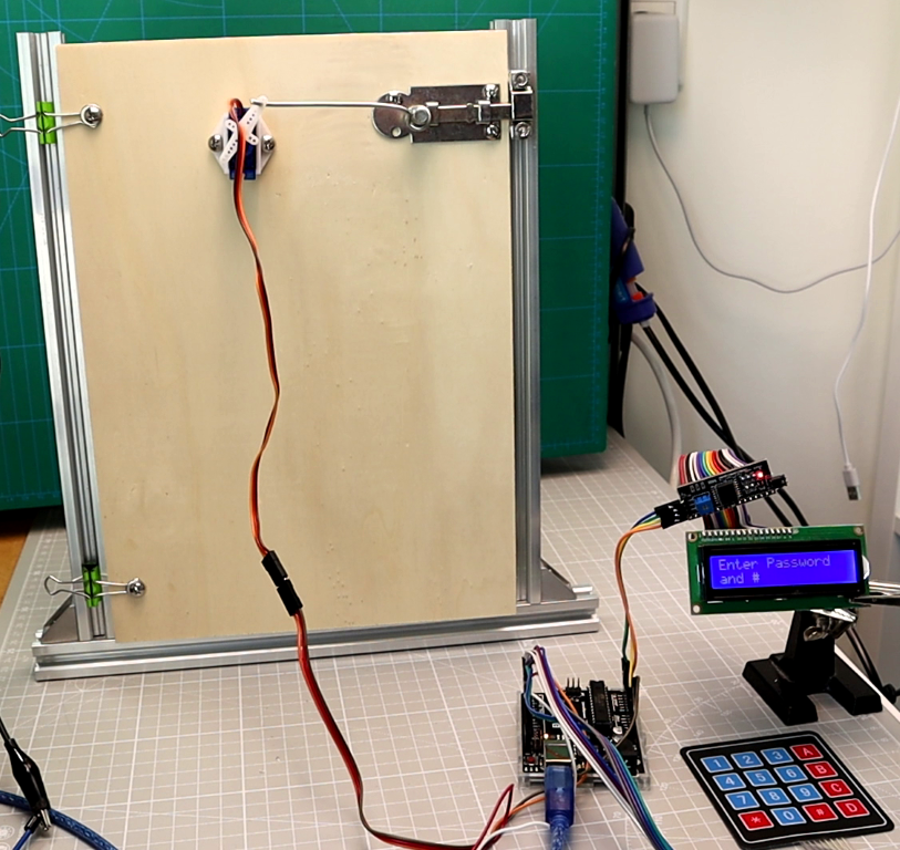
For the video I built a small test door: a plywood panel in a frame of aluminum extrusions, with two binder clips as hinges. The servo moves a metal barrel bolt.
How the lock works
The keypad is the input device. It has 16 keys (0–9, A–D, * and #) arranged in a matrix: 4 row wires and 4 column wires, with one key at each crossing. Pressing a key connects its row to its column, so 16 keys need only 8 pins. The Keypad library switches the rows one after another and reads the columns to find the pressed key.
The I2C LCD is the output. It shows “Enter Password” while the door is locked, one asterisk per typed key, “Door is OPEN” after a correct password and “Wrong Password” after a wrong one. I2C is a two-wire bus: SDA carries the data and SCL the clock. The I2C adapter is a small board soldered to the back of the display (also called a backpack). With it, the LCD needs these two signal wires plus 5 V and GND, instead of six or more signal wires.
The servo motor moves the latch. When you enter the correct password and confirm with #, the servo turns from the locked angle (LOCK_ANGLE, default 0°) to the open angle (UNLOCK_ANGLE, default 90°) and releases the latch. Pressing * sends it back to the locked position. If you are new to servo motors, read my servo motor tutorial.
Password logic and system flow
The sketch stores the password (default “1234”) in a String, a text variable. Each key you type (0–9, A–C) is added to an input buffer, a second String that holds the keys typed so far. When you press #, the sketch compares the buffer to the stored password. If they match, the door opens; otherwise the LCD shows an error. The * key clears the input or relocks the door, and D works as backspace.
The full flow:
- The LCD shows “Enter Password” on line 1 and “and #” on line 2, meaning: type the password, then press #.
- You type the password on the keypad. The LCD shows one asterisk (*) per key.
- Press # to submit. The Arduino compares your input to the stored password.
- If correct, the servo turns to the open angle (90° by default) and the LCD shows “Door is OPEN / Enter * to close”.
- The door stays open until you press *. Then the servo returns to the locked angle (0°).
- If the password is wrong, the LCD shows “Wrong Password / Try again” for 1.5 seconds, then shows “Enter Password” again.
Components required (bill of materials)
Most parts come in standard Arduino starter kits.
| Component | Qty | Required / Optional | Purpose | Notes |
|---|---|---|---|---|
| Arduino Uno (or compatible board) | 1 | Required | Main microcontroller | Nano: same pins as the Uno. Mega: connect SDA to pin 20 and SCL to pin 21 instead of A4 and A5 |
| 4×4 matrix keypad | 1 | Required | Password input (8 pins) | Membrane type (thin and flexible) is easiest to mount |
| 16×2 LCD with I2C adapter | 1 | Required | Prompts and feedback | Check the I2C address: usually 0x27 or 0x3F |
| SG90 servo motor | 1 | Required | Moves the latch | Powered from the external 5 V supply (see servo connections) |
| Jumper wires | ~20 | Required | All connections | Male-to-male and male-to-female |
| Breadboard | 1 | Required | Prototyping | Half-size or full-size |
| External 5 V power supply (1 A or more) | 1 | Required | Servo power | USB power alone can reset the Arduino when the servo moves |
| Small door latch or lock mechanism | 1 | Optional | Demo door or box | 3D-printed or off-the-shelf latch |
Circuit diagram and wiring
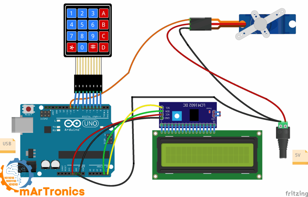
The LCD uses the two I2C pins A4 and A5, the keypad uses eight digital pins (D2 to D9), and the servo signal wire goes to D10.
LCD connections
| LCD I2C pin | Arduino pin | Notes |
|---|---|---|
| SDA | A4 | I2C data line |
| SCL | A5 | I2C clock line |
| VCC | 5 V | Power |
| GND | GND | Ground |
Keypad connections
| Keypad pin | Function | Arduino pin |
|---|---|---|
| Pin 1 | Row 1 | D9 |
| Pin 2 | Row 2 | D8 |
| Pin 3 | Row 3 | D7 |
| Pin 4 | Row 4 | D6 |
| Pin 5 | Column 1 | D5 |
| Pin 6 | Column 2 | D4 |
| Pin 7 | Column 3 | D3 |
| Pin 8 | Column 4 | D2 |
Servo connections
| Servo wire | Connects to | Notes |
|---|---|---|
| Signal (orange/yellow) | D10 | Servo signal. The Servo library works on any digital pin; D10 is free in this circuit |
| VCC (red) | + of the external 5 V supply | Do not connect this + to the Arduino 5V pin; only the grounds are joined |
| GND (brown/black) | GND of the supply, joined to Arduino GND | Common ground |
An SG90 draws about 100 mA when it moves freely and up to about 650 mA at stall (when the shaft is blocked, for example by a stuck latch). A standard USB port supplies 500 mA, so the voltage drops and the Arduino can reset. Power the servo from an external 5 V supply rated at 1 A or more. Connect the supply’s GND to the Arduino GND so both circuits share the same 0 V reference (common ground).
The Arduino sketch
Before uploading, install two libraries through Sketch → Include Library → Manage Libraries: “LiquidCrystal I2C” by Frank de Brabander and “Keypad” by Mark Stanley and Alexander Brevig. The Library Manager lists the first one with a space; the sketch includes it as LiquidCrystal_I2C.h. Several LCD libraries share this name and use different commands; this sketch needs the one by Frank de Brabander because it calls lcd.init(). Wire and Servo come with the Arduino IDE.
/**
Password Door Lock
 */
#include <Wire.h>
#include <LiquidCrystal_I2C.h>
#include <Keypad.h>
#include <Servo.h>
// LCD
#define LCD_ADDR 0x27
LiquidCrystal_I2C lcd(LCD_ADDR, 16, 2);
// Servo
#define SERVO_PIN 10
#define LOCK_ANGLE   0
#define UNLOCK_ANGLE 90
Servo lockServo;
// Keypad
const byte ROWS = 4;
const byte COLS = 4;
char keys[ROWS][COLS] = {
  {'1','2','3','A'},
  {'4','5','6','B'},
  {'7','8','9','C'},
  {'*','0','#','D'}
};
byte rowPins[ROWS] = {9, 8, 7, 6};
byte colPins[COLS] = {5, 4, 3, 2};
Keypad keypad = Keypad(makeKeymap(keys), rowPins, colPins, ROWS, COLS);
// Password
String PASSWORD = "1234";
String input = "";
bool doorUnlocked = false;
void lcdPromptLocked() {
  lcd.clear();
  lcd.setCursor(0,0);
  lcd.print("Enter Password");
  lcd.setCursor(0,1);
  lcd.print("and #");
}
void lcdPromptUnlocked() {
  lcd.clear();
  lcd.setCursor(0,0);
  lcd.print("Door is OPEN");
  lcd.setCursor(0,1);
  lcd.print("Enter * to close");
}
void lockDoor() {
  lockServo.write(LOCK_ANGLE);
  doorUnlocked = false;
  lcdPromptLocked();
  input = "";
}
void unlockDoor() {
  lockServo.write(UNLOCK_ANGLE);
  doorUnlocked = true;
  lcdPromptUnlocked();
  input = "";
}
void wrongPasswordMsg() {
  lcd.clear();
  lcd.setCursor(0,0);
  lcd.print("Wrong Password");
  lcd.setCursor(0,1);
  lcd.print("Try again");
  delay(1500);
  lcdPromptLocked();
  input = "";
}
void handleKey(char k) {
  if (doorUnlocked) {
    if (k == '*') lockDoor();
    return;
  }
  if (k == '#') {
    if (input == PASSWORD) unlockDoor();
    else wrongPasswordMsg();
    return;  // keep the new LCD screen
  } else if (k == '*') {
    input = "";
    lcdPromptLocked();
    return;  // keep the new LCD screen
  } else if (k == 'D') {
    if (input.length() > 0) input.remove(input.length()-1);
  } else {
    if (input.length() < 8) input += k;
  }
  lcd.setCursor(0,1);
  for (unsigned int i = 0; i < 8; i++) lcd.print(i < input.length() ? '*' : ' ');  // one '*' per typed key, blanks the rest
}
void setup() {
  lcd.init();
  lcd.backlight();
  lockServo.attach(SERVO_PIN);
  lockDoor();
}
void loop() {
  char key = keypad.getKey();
  if (key) handleKey(key);
}
Code breakdown
1) Libraries and objects
#include <Wire.h>
#include <LiquidCrystal_I2C.h>
#include <Keypad.h>
#include <Servo.h>
// LCD
#define LCD_ADDR 0x27
LiquidCrystal_I2C lcd(LCD_ADDR, 16, 2);
// Servo
#define SERVO_PIN 10
#define LOCK_ANGLE   0
#define UNLOCK_ANGLE 90
Servo lockServo;
The four libraries handle I2C communication (Wire), the LCD (LiquidCrystal_I2C), keypad scanning (Keypad) and servo control (Servo). The lcd and lockServo objects are created here and used throughout the sketch.
2) Hardware configuration (pins and angles)
#define LCD_ADDR 0x27
#define SERVO_PIN 10
#define LOCK_ANGLE 0
#define UNLOCK_ANGLE 90
A #define gives a fixed value a name; before compiling, the name is replaced by the value everywhere in the sketch. LCD_ADDR is the I2C address of the LCD’s I2C adapter. Most adapters use 0x27, some use 0x3F. An I2C scanner is a short sketch that tries every I2C address and prints each address that answers to the Serial Monitor. The Serial Monitor is the Arduino IDE window that shows text the board sends over USB. Run the scanner if the LCD shows blocks but no text, and set LCD_ADDR to the address it reports. SERVO_PIN is the pin that carries the servo signal. LOCK_ANGLE and UNLOCK_ANGLE set the two servo positions; adjust them to the range of your latch.
3) Keypad layout and wiring
const byte ROWS = 4, COLS = 4;
char keys[ROWS][COLS] = { ... };
byte rowPins[ROWS] = {9, 8, 7, 6};
byte colPins[COLS] = {5, 4, 3, 2};
Keypad keypad = Keypad(makeKeymap(keys), rowPins, colPins, ROWS, COLS);
The keys array maps the 4×4 key grid to characters. The row pins (9, 8, 7, 6) and column pins (5, 4, 3, 2) must match your wiring. On most membrane keypads, pin 1 is the leftmost pin when the keys face you: pins 1–4 are rows 1–4, pins 5–8 are columns 1–4. The Keypad library also handles debouncing: when a key is pressed, its contacts bounce open and closed for a few milliseconds, and the library filters this out so one press counts once.
4) Password state and variables
String PASSWORD = "1234";
String input = "";
bool doorUnlocked = false;
PASSWORD holds the password the user must enter: up to 8 characters from 0–9 and A–C. D, * and # cannot be part of it because they work as backspace, clear and submit. To change the password, find the line String PASSWORD = "1234";, replace 1234 with your new password and upload the sketch again. The variable input holds the keys typed so far, and doorUnlocked tracks whether the door is open.
Note: the String class reserves memory while the program runs. The Uno’s ATmega328P has only 2 KB of RAM, and many changes to Strings can split the free memory into small gaps that can no longer be used (fragmentation). For a lock that runs 24/7, a fixed char array is safer. A char array is a fixed-size row of characters that the compiler reserves once, so it does not fragment the memory.
5) LCD helper screens
void lcdPromptLocked() { ... }     // "Enter Password" / "and #"
void lcdPromptUnlocked() { ... }   // "Door is OPEN" / "Enter * to close"
Each screen has its own function, so you change a message in one place only.
6) Door control helpers
void lockDoor() { ... }
void unlockDoor() { ... }
lockDoor() turns the servo to LOCK_ANGLE, sets doorUnlocked to false, shows the locked prompt and clears the input buffer. The second function does the reverse: it turns the servo to UNLOCK_ANGLE, sets doorUnlocked to true, shows “Door is OPEN / Enter * to close” and clears the buffer as well.
7) Feedback on wrong password
void wrongPasswordMsg() { ... }
When the input does not match, the LCD shows “Wrong Password / Try again” for 1.5 seconds (delay(1500)), then returns to the locked prompt and clears the input. The pause gives you time to read the message.
8) Central input logic: handleKey()
void handleKey(char k) { ... }
handleKey() decides what each key press does:
- Door open: only * is accepted; it calls lockDoor(). All other keys are ignored while the door is open.
#(submit): compares the input buffer to PASSWORD. If they match, the door opens; otherwise the wrong-password message appears.*(clear): while locked, * clears the input buffer and resets the LCD prompt.D(backspace): removes the last character from the input buffer. D sits in the bottom-right corner next to #, so it is easy to reach when you correct a typo.- Any other key (0–9, A, B, C): is added to the input buffer as long as it holds fewer than 8 characters.
After a typed key or D, the last two lines of handleKey() rewrite line 2 of the LCD with one asterisk per character in the buffer, so the password itself never appears on the display. The # and * branches end with return, so the screen they have drawn (for example “Door is OPEN / Enter * to close”) stays as it is.
9) Setup: one-time initialization
void setup() {
  lcd.init(); lcd.backlight();
  lockServo.attach(SERVO_PIN);
  lockDoor();                      // start locked
}
setup() runs once at power-on and after every reset. It initializes the LCD, switches on the backlight, attaches the servo to D10 and calls lockDoor(), so the lock always starts locked and shows “Enter Password”.
10) Loop: read keys and react
void loop() {
  char key = keypad.getKey();
  if (key) handleKey(key);
}
keypad.getKey() checks the keypad once on every pass of loop() and returns the pressed key, or 0 when no key is pressed. This repeated checking is called polling. Apart from the 1.5 s pause after a wrong password, the program never waits (blocks), so it registers every key press immediately.
How to test and calibrate the lock
Test each part before you mount the lock on a door or in a box.
Verify keypad input
Add Serial.begin(9600); to setup() and change the line in loop() to if (key) { Serial.println(key); handleKey(key); }. Upload, open the Serial Monitor at 9600 baud (the transfer speed set by Serial.begin(9600)) and press each key: the matching character should appear. Remove the debug lines afterwards.
Verify LCD output
After power-on, the LCD shows “Enter Password” on line 1 and “and #” on line 2. In my build, line 1 first showed a row of blocks, and the prompt appeared once the sketch had started. The blocks only mean that the LCD has power but no commands yet. My LCD worked with the default address 0x27. If the prompt does not appear, work through the three LCD rows in the troubleshooting table.
Test servo direction and angles
Enter the correct password and press #. The servo should turn from 0° to 90° (or the values you set for LOCK_ANGLE and UNLOCK_ANGLE). If it turns the wrong way, swap the values of LOCK_ANGLE and UNLOCK_ANGLE. Then adjust both values in small steps (for example 10° and 80°) until the latch engages and releases smoothly. Some latches need the full 0° to 180°, others only 0° to 45°.
Check mechanical alignment
Upload the sketch first: setup() moves the servo to LOCK_ANGLE. Then press the servo horn (the plastic arm on the shaft) onto the shaft so that it holds the latch bolt in the locked position. Run the open and relock cycle several times and check that the latch does not stick or jam. On my test door, the servo sits in a plastic holder screwed to the panel, and a bent piece of stiff wire links the servo horn to the knob of the barrel bolt. The default angles of 0° and 90° slide the bolt in and out.
Test with external servo power
If the servo jitters or the Arduino resets when the servo moves, power the servo as described under servo connections.
Troubleshooting common issues
| Problem | Likely cause | Solution |
|---|---|---|
| LCD backlight stays off | No power to the LCD | Check VCC (5 V) and GND on the I2C adapter. |
| Backlight on, nothing visible | Contrast too low | Turn the contrast potentiometer (the small blue trimmer on the I2C adapter) slowly until text or a row of blocks appears. |
| Blocks but no text | The LCD receives no commands: wrong I2C address or an SDA/SCL wiring error | Check SDA (A4) and SCL (A5). Run an I2C scanner sketch and set LCD_ADDR to the address it reports (usually 0x27 or 0x3F). |
| Keypad does not respond | Wiring error | Check that the eight keypad wires go to D2 to D9 as in the wiring table. |
| Keys return wrong characters | Row and column pins swapped or in the wrong order | Rearrange the rowPins and colPins arrays to match your wiring. |
| Servo jitters or resets the Arduino | Servo powered from USB | Power the servo from the external 5 V supply (1 A or more) and join the grounds (see servo connections). |
| Servo turns the wrong way | LOCK_ANGLE and UNLOCK_ANGLE swapped | Swap the two values. |
| Open angle does not release the latch | Angle does not match the mechanism | Adjust UNLOCK_ANGLE in steps of 5–10° until the latch releases. |
| Correct password always shows “Wrong” | PASSWORD is longer than 8 characters (input stops at 8), contains D, * or # (these keys never reach the input), or has a typo | Print the input variable to the Serial Monitor to see what is compared. |
| Servo works once, then stops | Voltage dip (brownout) when the servo starts | Add a 470 µF electrolytic capacitor (rated 10 V or more) between the servo’s 5 V and GND, close to the servo. Mind the polarity: the long leg (+) goes to 5 V, the leg on the striped side (−) goes to GND. Or use a stronger supply. |
| Compilation error: library not found | Libraries not installed | Install LiquidCrystal I2C and Keypad through the Arduino IDE Library Manager (Wire and Servo come with the IDE). |
Customize and upgrade the lock
Software upgrades
- EEPROM-stored password: store the password in the EEPROM, a small memory inside the Arduino that keeps its content without power. Then it survives a restart. Add a “change password” mode on key A: the user enters the old password, then the new one. A then works as a control key and can no longer be part of a password.
- Lockout after failed attempts: add a counter that disables input for 30–60 seconds after 3 wrong attempts. This slows down brute-force guessing (trying one password after another): with a 60 s lockout after every 3 wrong tries, testing all 10,000 four-digit passwords takes more than two days.
- Multiple user passwords: store an array of valid passwords so each person has their own.
- Auto-relock timer: relock the door if nobody presses * within a set time (for example 10 seconds).
Hardware upgrades
- Buzzer feedback: add a buzzer that beeps on each key press, plays a tone on a correct password and sounds an alarm after repeated failures. An active buzzer beeps when its pin is set HIGH (5 V); a passive buzzer needs tone() to make a sound. The sketch above does not use a buzzer.
- Relay and electric strike: for a permanent installation, replace the servo with a relay module, a switch that the Arduino turns on and off through one pin. The relay switches an electric strike (a door frame part that releases the latch electrically) or a magnetic lock (an electromagnet that holds the door shut). These usually run on 12 V from their own supply. A magnetic lock opens when power fails (fail-safe); electric strikes come as fail-safe or fail-secure (stays locked without power), so choose the type on purpose.
- Battery backup: a Li-ion cell (3.7 V) with a charging module and a 5 V boost converter (a module that raises the voltage to 5 V) keeps the lock running during a power cut.
- Bluetooth (HC-05): lets you open the lock from a phone app. It adds a second way in, so change the module’s default pairing PIN (often 1234 or 0000). My HC-05 Bluetooth tutorial covers wiring and pairing.
Access and security options
- RFID access: an RFID reader (such as the RC522) reads contactless cards and key fobs. Add one next to the keypad for two-factor authentication: card plus password.
- Data logging: log access attempts with timestamps from a DS3231 RTC (real-time clock) module to an SD card.
- Tamper detection: a vibration sensor or a magnetic reed switch (a contact that switches when a magnet on the door moves away) detects forced entry and triggers an alarm.
Frequently asked questions
A 3×4 keypad has no A–D column, so you lose the D backspace; * (clear/relock) and # (submit) still work. Set COLS to 3, remove the last column from the keys array, give colPins three pins and connect seven wires instead of eight.
Store it with the Arduino EEPROM library: write the password to EEPROM when it changes and read it back in setup(). Each EEPROM cell lasts about 100,000 writes, so write only when the password changes.
Resources and related tutorials
Library documentation
- LiquidCrystal_I2C library: GitHub repository with documentation and examples.
- Keypad library: source code and examples on GitHub.
Related OmArTronics tutorials
- Control a Servo Motor with Joystick and OLED Display: servo control and display output.
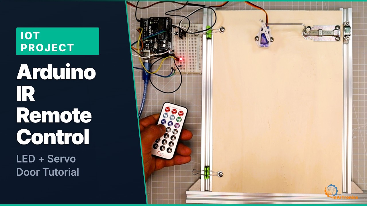
- Arduino IR Remote LED and Servo Door: the same kind of servo door, opened with an infrared remote instead of a keypad.
- HC-05/HC-06 Bluetooth Module Tutorial: the basis for the Bluetooth upgrade.
- Arduino Radar with Ultrasonic Sensor and Servo Motor: another servo project, with a sweeping ultrasonic sensor.
1 thought on “Arduino Password Door Lock with Keypad and LCD”