
This post contains affiliate links, marked with *. As an Amazon Associate I earn from qualifying purchases, at no extra cost to you. It helps keep the tutorials free.
OmArm One Series
- Part 1: Build, statics and payload (this post).
- Part 1.5: Drive it with a game controller.
- Part 2: Digital twin, URDF in RViz and Gazebo.
- Part 3: MoveIt 2 and ros2_control on real hardware (video).
- Part 4: Computer vision pick and place (coming soon).
- Part 5: AI: grasping by name, by voice (coming soon).
New here? This arm is the successor of OmArm Zero, the $50 build this series grew out of. You do not need Zero to follow along, but the design decisions below make more sense if you know where they came from.
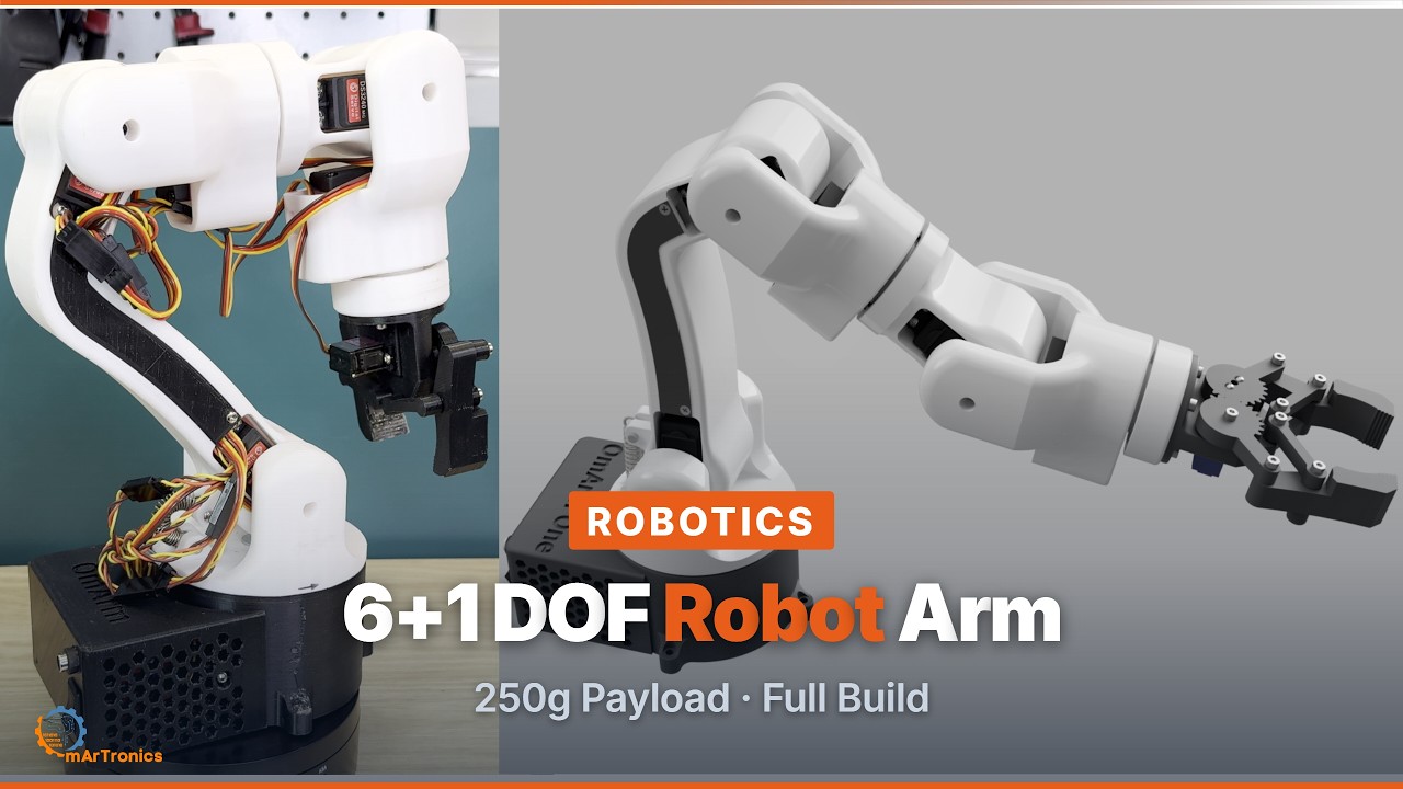
The video loads from YouTube (Google), which may set cookies. Privacy policy
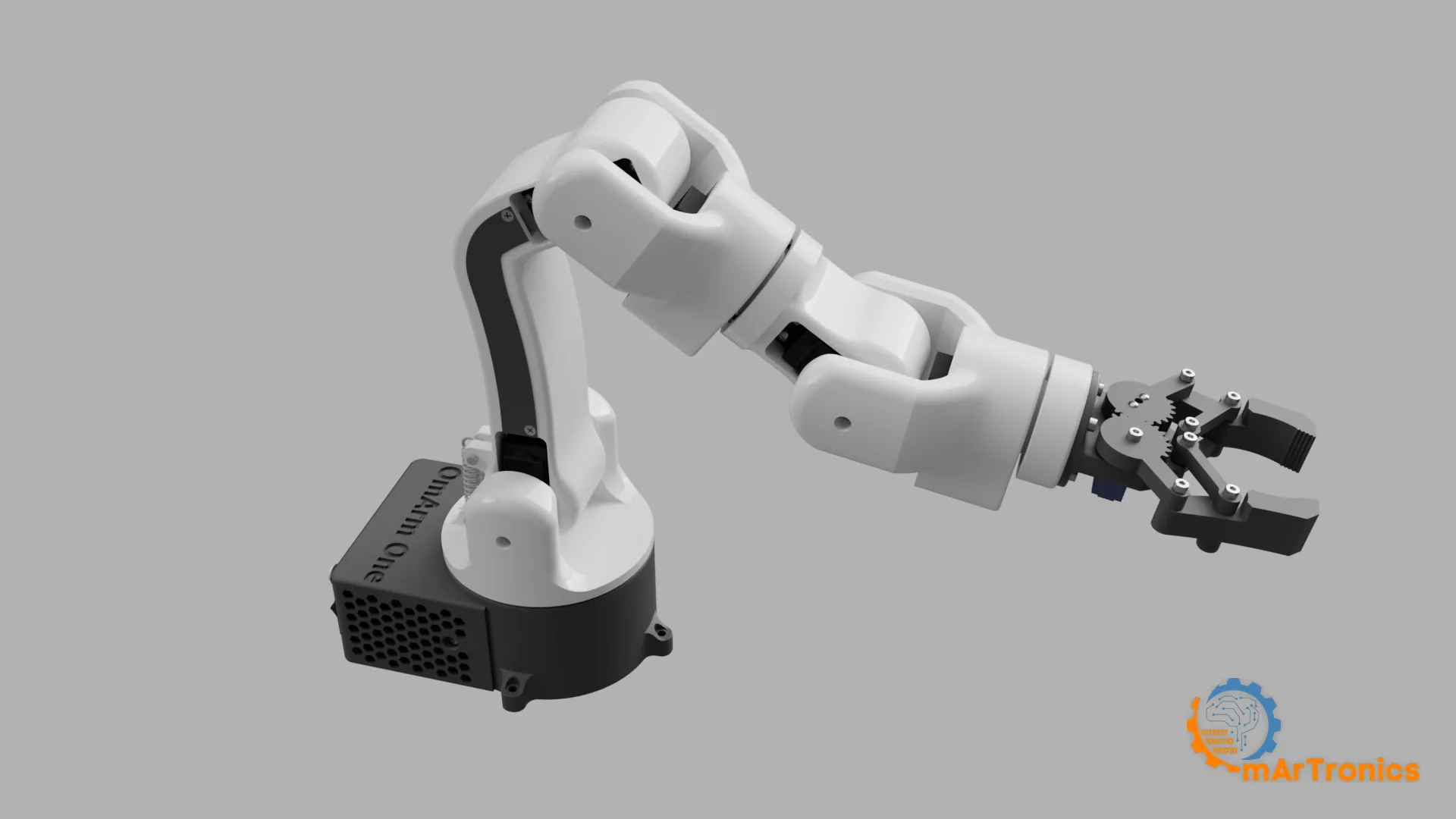
This is a 3D printed robot arm with six joints and a gripper. The 7 in 7-DOF (degrees of freedom, the number of independently driven axes) counts the gripper: six positioning joints (J1 to J6) plus the gripper drive (J7). Every joint that takes a bending moment runs on a steel ball bearing, so the servo gear trains only deliver torque. A moment is the turning effect of a force about an axis: force times lever arm. The base sits on a 51110 thrust bearing and a 6806ZZ radial bearing; the pitch joints use a fixed-loose arrangement around a 695ZZ, explained in section 5. The arm reaches 485 mm, carries 200 g nominal and 250 g maximum at a 300 mm working radius, and weighs 1283 g.
The torque figures come from a CAD mass model that scans the joint space for each joint’s worst pose. The payload table applies the same model at 63 % of stall, and the analysis script that produced both is in the repository.
At a glance
Time required: 15 h 6 min of printing across two plates on a Bambu Lab P1S, unattended. Assembly and testing add about three hours.
Total cost: ca. 210 to 360 € at August 2026 prices if you buy every part new, in whole packs. The six DS3240 servos are 40 to 43 % of that. Section 6 breaks the total down, including the lower figure if you already own a printer, filament and a 6 V supply.
Difficulty: Intermediate. If you built OmArm Zero, this is the same kind of work, with heavier parts and press-fitted bearings.
Safety: The arm can pinch hard enough to hurt, and the supply delivers high current. Section 7 starts with five habits that cover it. Read them before the first power-up.
What you should already be comfortable with: flashing an ESP32 from the Arduino IDE and slicing an STL. You will also read a caliper more than once. You do not need robotics math. Three terms come up throughout. Stall torque is the highest torque a servo can produce; at that load its output shaft stops turning. A horn is the splined plastic arm that clamps onto the servo’s output shaft. Backlash is the free play you feel when you wiggle a gear train that is supposed to be locked. Sections 4 and 5 are the theory; you can skip them on a first read and come back when a number in the build surprises you.
Tools you’ll need (section 6 lists every fastener):
- 2.5 mm hex key; the fourteen M3 socket-head screws all take the same one.
- 8 mm spanner or socket for the three M5 bolts and their nuts.
- Phillips PH0 and PH1 for the 63 self-tapping screws and the M1.6 in the gripper.
- Pozidriv PZ1 for the two M3 pozidriv screws.
- A caliper, for measuring the bearing seats in step 3 of section 7.
- Soldering iron and heat-shrink for the supply wiring in the base; the iron also sets the eight M3 heat-set inserts in the gripper.
- A 3D printer with a 256 mm bed; the parts are laid out for a Bambu Lab P1S.
Files you’ll need: the STLs, the firmware and the Bambu Studio print project. The package is in the shop and the firmware is on GitHub; both links are in the Resources at the end.
Start here:
- Order the parts; section 6 has the shop table with prices.
- Start both print plates while you wait; section 5 has the settings.
- Wire the base before any assembly; section 8 has the wiring, and step 1 in section 7 explains why it comes first.
- Read the five safety habits at the top of section 7, then build steps 1 to 16.
- When something misbehaves, go to section 11.
1. Why build a 3D printed robot arm from scratch (again)?
OmArm Zero was supposed to be a one-off: one arm, built to see whether it could be done cheaply. Five joints plus a gripper, 303 mm reach, 100 g payload (150 g with the shoulder spring), about $50 in parts, controlled from a web browser served by an ESP32. It ended up carrying a four-part series: the build, URDF export, ROS 2 motion planning and computer vision. URDF (Unified Robot Description Format) is a file that describes the arm’s links and joints. ROS 2 (Robot Operating System 2) is a software framework that connects sensors, planners and motor drivers. By the end of it I had a long list of what I would do differently.
What I wanted next was an arm that I no longer steer by hand. An arm that follows sliders can be soft and approximate, because a human corrects it. An arm that executes a planner’s instruction unsupervised cannot be either.
It has to lift 200 g all day and 250 g when asked. It must hold that load anywhere within a 300 mm working radius, in the worst pose for that radius, without a servo overheating. Zero managed 150 g at full stretch with a spring helping the shoulder, and that was its ceiling.
It has to have six joints, not five. Five joints let you put the gripper somewhere. Six let you put it there from a chosen direction, and that difference decides whether Parts 3 to 5 of this series work at all. A camera that finds an object also tells you how it is oriented.
Every joint that carries a moment gets a bearing. This requirement shapes more of the design than any other on the list.
On Zero the base was a printed platform screwed to a servo horn, with one small 6806ZZ bearing steadying the shaft. When the arm reaches out, gravity also tries to tip the base, and that tipping moment ran through the horn into the servo’s gear train. That was acceptable for Zero’s 535 g arm, but not for a heavier arm with more reach. The moment grows with both weight and reach, and a servo output shaft is built only to deliver torque.
On One the servo delivers torque and the bearings carry everything else. A 51110 thrust bearing takes the weight of the arm at the base and a 6806ZZ radial bearing takes the tipping. Every pitch joint gets a fixed-loose bearing arrangement, so the printed fork is supported on both sides. Section 5 walks through each one.
The difference shows before anything is powered on. If you rock a horn-mounted arm by the wrist, the gear train moves through its backlash. Press down on this one at full stretch and the load goes into the base bearings. Section 10 turns that into a check you can run, including which direction to push and which one tells you nothing.
One rule carries over from Zero: every component is chosen by calculation first and catalogue second. The torque analysis comes before the parts list, the payload table before the payload test, and every payload claim is tied to a working radius. As with Zero, the arm was designed for the whole series from the start, which is why the serial protocol, the joint conventions and the shape of the workspace look the way they do.
2. What the arm can already do

Motion that does not lurch
Every point-to-point move runs a coordinated quintic profile, a fifth-order position curve chosen so that speed and acceleration both start and end at zero. All seven joints share one duration, so they start and arrive together. That matters more on a 485 mm arm than on a small one, because a lurch at the shoulder becomes a visible whip at the fingertips.
Dragging a slider is a different problem with a different solution. The target keeps moving while the arm chases it, so planning a trajectory is pointless. Each joint instead follows with limited acceleration, braking early enough that it cannot overshoot. Both paths respect the same velocity and acceleration ceilings, and both are bounded per control tick, so a stalled WiFi request or a slow HTTP call can never turn into one giant step. The motion core is plain math with no Arduino dependencies, so it compiles and runs on a PC against the same header the ESP32 executes.

A safety model for an arm that can hurt you
This arm has no position feedback, so after a reset it does not know where it is. The firmware treats that as a safety problem. Nothing moves on boot. A lost position has to be confirmed by a human before the servos come back. The first move after any boot is stretched to at least four seconds, and the emergency stop holds until you release it. Section 8 walks through the whole model, including the reset case that surprises people: a firmware upload counts as a power loss.
Resolution finer than the servo’s dead band
The six joint servos run from a PCA9685 driver board at 250 Hz, five times the classic servo rate. One PWM count (PWM, pulse-width modulation: the width of a repeating pulse tells the servo its target angle) is then 0.086 degrees at the joint. The DS3240’s own dead band, the smallest command change a servo responds to, is 0.27 degrees. The servo’s own dead band now sets the resolution limit, and the repeatability check in section 10 tests against that floor. Section 8 has the reasoning and the trap inside it.

Three firmwares, one wiring
The same board, the same channels and the same conventions carry three builds: the two below, plus the game-controller firmware from Part 1.5.
The web app firmware brings up its own WiFi access point and serves a control interface. It has seven joint sliders, a speed control, a home command, an emergency stop and a small sequence editor. The editor records poses and plays them back with a configurable delay. Sequences export and import as files, so a demo you set up once survives a reflash. The interface lives in the ESP32.
The ROS 2 serial firmware drops WiFi, the web app and the filesystem, which keeps it small and keeps anything that could disturb servo timing out of the way. It adds what a planner needs: trajectory following, where a whole path is loaded and validated completely before anything moves. The check covers joint ranges, the speed ceiling, the timing, and whether the trajectory starts where the arm is standing, within five degrees. If it fails validation, you get a refusal with a reason, and nothing moves. That validation-before-execution rule is the part I am most pleased with. It comes from watching Zero’s ROS 2 serial bridge quietly execute only the last waypoint of a plan.
Switching between them is a reflash. The stored arm position survives, so the arm does not move when you switch firmware. Both compile clean on the current ESP32 core: the web-app build fills 80 percent of the 1.25 MB app partition (the flash area that holds the program), the ROS 2 serial firmware 26 percent.
3. Where this series is going
The series has five parts plus Part 1.5, in the order a real project runs, and each part ends with working hardware or software.

| Part | What gets built | What you learn |
|---|---|---|
| 1 (this post) | The physical arm: requirements, statics, CAD, BOM, printing, assembly, wiring, calibration, payload test | Requirements engineering, torque and payload analysis from a free-body diagram (a sketch of every force acting on one part), bearing selection, design for FDM (fused deposition modelling, filament 3D printing), component selection with numbers behind it, forward kinematics (computing the hand position from the joint angles) and DH parameters, an ESP32 control stack with a web interface |
| 1.5 | Driving the arm with a Bluetooth game controller | Velocity control from an analog stick, dead zone, expo curve (a response curve that makes small stick movements finer) and a filtered command, a second ESP32 firmware on the Bluepad32 stack, pairing a DualShock 3, and a pose sequence stored in flash |
| 2 | The digital twin (a simulated copy of the arm that matches the real one) | Exporting a URDF from the CAD, auditing it against the real arm, visualisation in RViz (the 3D viewer of ROS 2), simulation in Gazebo (a physics simulator) |
| 3 | Motion planning | MoveIt 2 (the motion-planning framework for ROS 2), inverse kinematics (working out joint angles from a desired hand position) on a non-spherical wrist, trajectory planning, collision awareness, the serial firmware and ROS 2 driver for the real arm, and executing planned paths on the hardware |
| 4 | Eyes | Camera integration, hand-eye calibration (measuring where the camera sits relative to the arm), and pick and place of a detected object |
| 5 | Judgment | Grasping without markers: the arm finds arbitrary objects and picks the class you name |
Slider control, as in this part, does not need an arm built to this standard. Parts 4 and 5 do. Picture the end state: you say “pick up the red one”. A camera looks at the table, a model decides which object that is, a planner works out how to approach it, and the arm does it. Swap the model for a language model and the same sentence can come from speech, from a chat window or from another program.

Object detection returns positions in millimetres, so the arm has to be repeatable in millimetres. An autonomous cycle repeats a motion far more often than a human demo does, and it finds every edge case you did not test. The failure behaviour therefore has to be safe without relying on the operator’s attention. Section 4 turns these demands into requirements.
None of that AI exists yet. Parts 4 and 5 build it, and I will write up what happens when I get there, including what does not work. The machine underneath has to be ready first, and building the mechanics for the demanding case is cheaper than rebuilding an arm that turned out too soft for it.
4. System requirements and engineering specification
Before I drew a single part I wrote down what this arm has to do. For One the list is shorter than Zero’s and harder.
Functional requirements
F1. Payload: 200 g nominal and 250 g maximum, both sustained at a 300 mm working radius. Nominal is the duty the arm lives at; maximum is what it must still hold within the thermal rule. Sustained means the servos hold it indefinitely without overheating, at the worst joint configuration that reaches that radius.
F2. Reach: at least 480 mm horizontally from the base axis to the closed gripper. Zero reached 303 mm, so this is around 60 percent more, enough to cover a desk.
F3. Six positioning joints plus a parallel-jaw gripper. Base yaw, shoulder pitch, elbow pitch, forearm roll, wrist pitch, tool roll. With six the planner picks the approach direction as well as the target point.
F4. Bearings, not servo horns, carry the moments. No joint may transfer its bending load through the servo output shaft alone. Where the moment is negligible, show the number.
F5. Control: WiFi web GUI for standalone use, USB serial for ROS 2. Same dual interface as Zero, same wiring for both.
F6. Angle convention: every joint 0 to 180 degrees, CAD angle equals servo angle. No offset tables and no per-joint sign flips in the firmware. The CAD export in Part 2 still needed four direction flips, four frame rotations and two zero corrections. Part 2 writes them into the URDF, so the model angle stays equal to the servo angle.
F7. Resolution floor set by the servo. The DS3240’s dead band is 3 microseconds, which over its 500 to 2500 microsecond range works out to 0.27 degrees. The mechanics must not add play on top of that.
Non-functional requirements
One servo model for all six joints. Zero mixed MG996R and SG90 to save weight where torque was not needed. One uses a single model: one spare covers any joint, one calibration procedure covers the arm, one mounting geometry repeats through the whole CAD. The cost is carrying shoulder-class torque out at the wrist, and the torque budget below makes that affordable.
Torque margin: the worst-case torque at every joint, at the 250 g maximum, stays at or below 63 percent of stall, computed with conservative masses and with no help from the shoulder spring. This single rule drives the servo choice.
Power: one 6 V rail, 10 A or more, with bulk capacitance for transients. 6 V is the standard rail, because the 250 g maximum needs the torque the DS3240 only makes there, and the SG90 gripper caps the voltage at that value (section 6).
Printability: every structural part on a Bambu Lab P1S (256 mm bed) in PLA. Eighteen printed bodies, 23 pieces. The two print plates hold 22 of them; print base_link_upper from 02_base_link_upper.stl.
Assembly with a normal maker toolbox. No CNC, no laser cutting, no press tooling.
Kinematic layout
Six revolute (rotating) joints in series. The proportions matter as much as the count, so here they are measured along the chain.
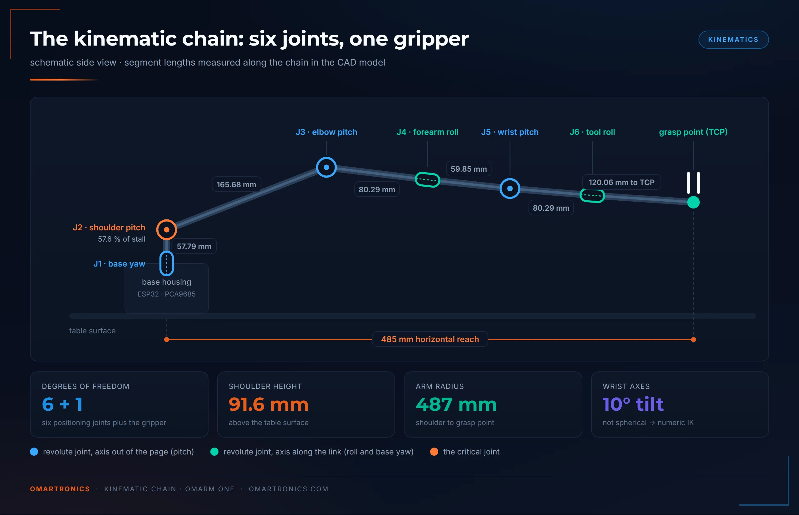
J1, base yaw. Rotates the whole arm about the vertical axis, 0 to 180 degrees. Gravity produces no torque about a vertical axis, but the reaching arm produces a tipping moment that grows with reach. A bearing takes that moment, as section 5 shows.
J2, shoulder pitch. Sits 91.6 mm above the table, 57.79 mm along the chain from J1. This joint carries the arm. Everything beyond it acts on a lever up to half a metre long, and the analysis below confirms it is the critical joint of the machine.
J3, elbow pitch. 165.68 mm from the shoulder, which is the upper arm span. Carries the forearm, wrist and gripper.
J4, forearm roll. 80.29 mm past the elbow. Rotates the entire wrist assembly about the forearm axis.
J5, wrist pitch. 59.85 mm further out. Pitches the gripper up and down.
J6, tool roll. Another 80.29 mm out. Rotates the gripper about its own axis.
Gripper. Gear-driven parallel jaws, grasp point 120.06 mm beyond the tool flange (the mounting face at the end of the arm). Every reach and payload number in this post is quoted at that grasp point.
The two roll axes are tilted 10 degrees against the forearm; section 5 explains what that costs.
Denavit-Hartenberg parameters
New to robotics? Skip this table. Denavit-Hartenberg (DH) parameters are a standard set of four numbers per joint that fully describe a robot’s geometry. This table is computed from the same robot description (URDF) as the digital twin in Part 2.
In the table, a is the link length, alpha the twist between joint axes, d the offset along the previous axis, theta the joint variable. The offsets in the last column are the difference between the DH zero and the servo zero; they exist because the arm was drawn first and parameterised afterwards. They do not break F6: the CAD angle still equals the servo angle, and these numbers only relate that shared angle to the convention’s own zero.
| i | a (mm) | alpha (deg) | d (mm) | theta |
|---|---|---|---|---|
| 1 | 0.00 | −90.00 | 0.00 | q1 |
| 2 | 165.68 | 180.00 | −30.63 | q2 − 152.66° |
| 3 | 0.50 | −90.00 | −30.63 | q3 + 107.12° |
| 4 | 0.00 | −90.00 | 125.46 | q4 + 180.00° |
| 5 | 0.50 | −90.00 | 0.27 | q5 + 90.00° |
| 6 | 0.00 | 0.00 | 74.21 | q6 + 90.00° |
The 0.50 mm figures in the a column are real: the CAD carries a half-millimetre lateral offset between the pitch axes and the roll axes. The alpha column holds clean multiples of 90 degrees despite the 10 degree roll tilt, because the tilt lies in the plane of the common normal (the line perpendicular to both joint axes). The convention folds it into the offsets instead of the twist.
The table is checked automatically. The analysis script builds the forward kinematics from these rows and matches it against the URDF over 2000 random configurations. It refuses to print a table whose reach falls short of the measured 485 mm.
Torque analysis
For a joint holding the arm against gravity, the worst-case static torque is
tau = sum over all links beyond the joint of ( m_link * g * horizontal_distance_to_axis )
evaluated at the worst pose that joint can be commanded into. On Zero I did this with four lumped masses and a calculator. One has six joints and twelve bodies, so the CAD mass model scans the joint space for each joint’s worst case.
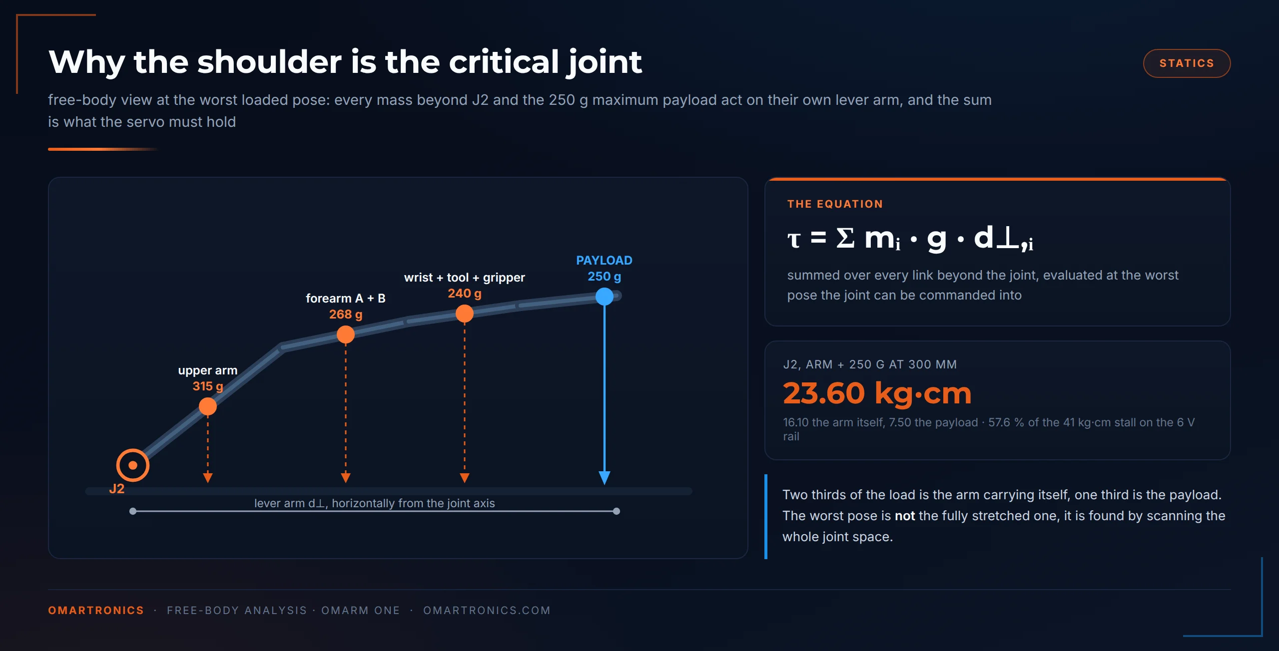
The masses come from the CAD solids, and they contain two large errors that point in opposite directions. The model treats every printed part as solid material, while the real parts are shell plus infill (solid outer walls around a partly hollow inside), so it over-counts the plastic. It also carries no servos, bearings, screws or wiring, so the hardware is missing. After assembly the complete machine weighed 1283 g on a kitchen scale, against the solid model’s 1284 g. The match comes from two errors cancelling out: the roughly 860 g of hardware the model ignores (servos, bearings, 86 fasteners, boards, wiring) almost exactly replaces the plastic that shell-and-infill printing saves. Entered into the analysis script as MEASURED, the scale factor comes out at 0.999, and every torque and payload figure below moves by a tenth of a percent.
This table gives the torque each joint needs with the arm carrying the F1 maximum of 250 g at a 300 mm radius, the load case the motors are sized against. Each joint is scanned in its own worst pose, and the first two columns are the two parts of the same sum.
| Joint | Arm itself | Payload | M required (kg·cm) | Stall needed, M/0.63 | What it means |
|---|---|---|---|---|---|
| J1 base yaw | 0.00 | 0.00 | 0.00 | 0.0 | no gravity torque, but the largest bending moment on the arm |
| J2 shoulder | 16.10 | 7.50 | 23.60 | 37.5 | the critical joint, this row sizes the servo |
| J3 elbow | 6.21 | 7.99 | 14.20 | 22.5 | second worst, and now more payload than arm |
| J4 forearm roll | 1.46 | 4.85 | 6.31 | 10.0 | payload dominates from here out |
| J5 wrist pitch | 1.46 | 4.85 | 6.31 | 10.0 | same |
| J6 tool roll | 0.01 | 0.31 | 0.33 | 0.5 | negligible; section 5 comes back to this number |
The largest requirement on the whole arm is 37.5 kg·cm, and that single number picks both the servo class and the rail voltage. The DS3240 delivers 36 kg·cm at 5 V and 41 kg·cm at 6 V, so 6 V is the standard rail on this arm, because the 250 g maximum needs it. At 5 V the arm still meets the 200 g nominal case, which asks for 35.1.
Two more points from that table. The ratio of arm to payload flips along the chain, from 68 percent structure at the shoulder to 23 percent at the mid-arm joints. A lighter forearm therefore adds more payload than a bigger servo does. And the shoulder needs 23.60 kg·cm where the elbow needs 14.20, so one joint decides the whole machine.
To check that the model is conservative, I rebuilt the shoulder moment from components.
- Printed structure beyond J2: 248 g, from PLA at 1.24 g/cm3 and a 24 percent fill calibrated against the slicer’s measured 421 g.
- Hardware the model does not carry: five DS3240 at 58 g each and the SG90, at the joints they sit in, out to 365 mm. Plus three 695ZZ at 2.31 g, the three M5 axles, 40 screws, five horns, eight brass inserts, the spring and 1.6 m of servo cable. Together 419 g.
- Result: 15.13 kg·cm against the model’s 16.10 for the same load case.
The build-up accounts for 1199 g of the weighed arm. If every unaccounted gram sits beyond the shoulder, the moment still lands at or below the model. The model therefore never underestimates, and the 23.60 kg·cm is a ceiling.
Payload derivation: where the 200 g and the 250 g come from
At stall torque the motor stops dead and draws its maximum current, 3.1 A at 5 V for the DS3240. A servo held near stall overheats within minutes, so payload is never specified against stall. Testing on Zero settled the ceiling at 63 percent of stall for sustained load, and that rule carries over unchanged.
Payload then falls out pose by pose. Take the torque headroom left at each joint and divide it by the payload’s lever arm about that joint. The smallest result across all six joints sets what the arm can hold in that pose. Do that across the workspace and you get a payload spec in its useful form: a table against working radius.
| Working radius | 6 V sustained | 6 V at stall | 5 V sustained | 5 V at stall |
|---|---|---|---|---|
| 250 mm | 407 g | 1013 g | 281 g | 813 g |
| 300 mm, requirement F1 | 325 g | 830 g | 219 g | 664 g |
| 303 mm (Zero’s full reach) | 321 g | 821 g | 217 g | 656 g |
| 350 mm | 268 g | 701 g | 178 g | 558 g |
| 370 mm, the 250 g maximum | 252 g | 661 g | 167 g | 526 g |
| 400 mm | 225 g | 605 g | 146 g | 480 g |
| 435 mm, the 200 g nominal | 202 g | 551 g | 129 g | 436 g |
| 485 mm (full stretch) | 175 g | 488 g | 110 g | 385 g |
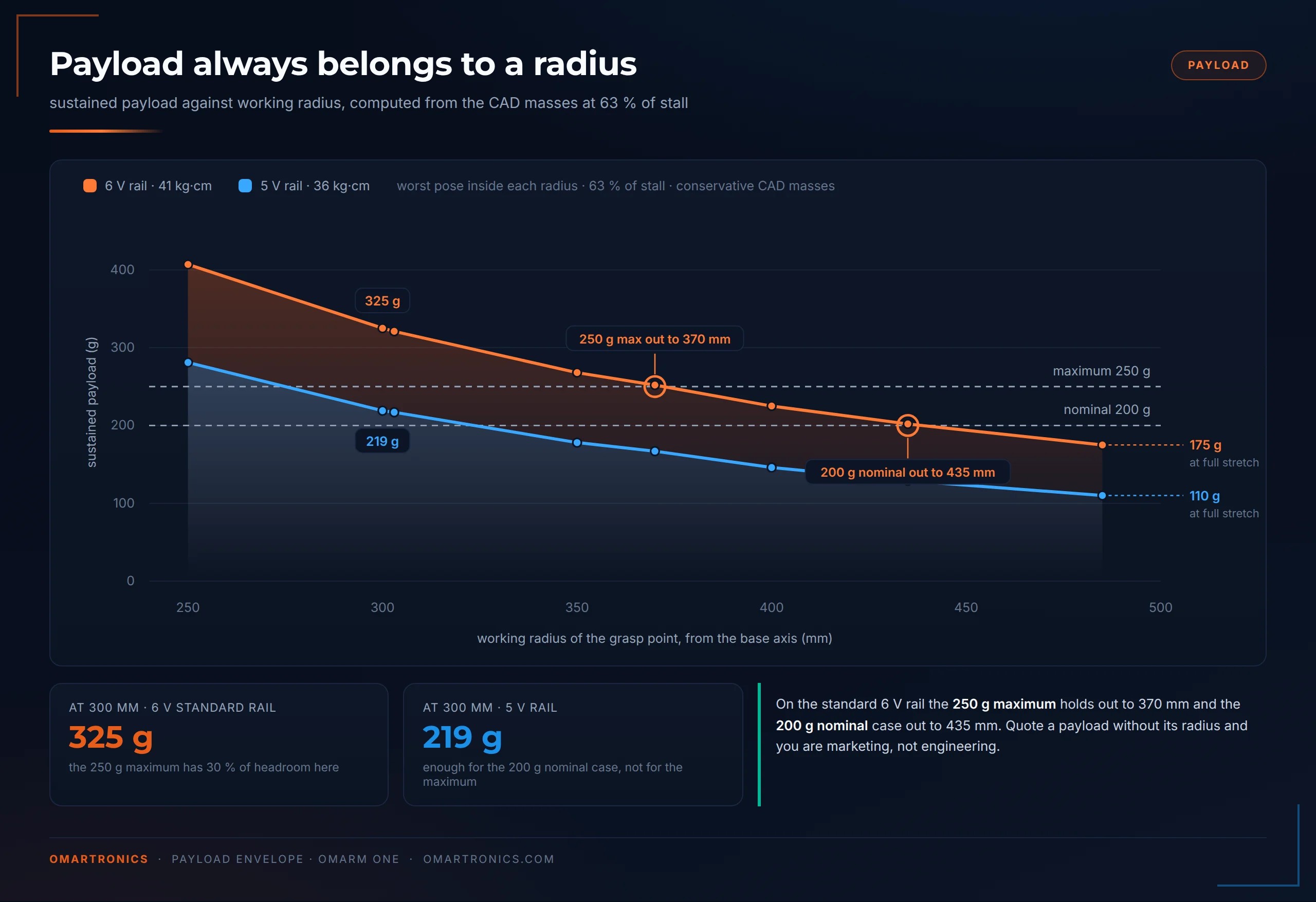
The 6 V columns are the ones that count. The 5 V columns are there because many benches have a 5 V supply, and they show what it costs. The same servo drops from 41 to 36 kg·cm, and at 300 mm the envelope falls from 325 g to 219 g. Enough for the 200 g nominal case, not for the 250 g maximum.
Requirement F1 checks out with room to spare. At a 300 mm working radius the arm sustains 325 g on the standard rail. Holding the 250 g maximum there loads the worst joint to 57.6 percent of stall, under the 63 percent line. J2 is the binding joint in every loaded pose. Scanned with each joint in its own worst loaded configuration at the maximum, J3 comes second at 34.6 percent, the two mid-arm joints reach 15.4, and the tool roll stays under 1. The 250 g maximum runs out at 370 mm and the 200 g nominal case at 435 mm. Those two radii are the edge of the spec; anything beyond them belongs to the lighter rows of the table.
The same table answers two questions I had about Zero. At Zero’s full reach of 303 mm this arm sustains 321 g where Zero managed 150 g, more than twice the payload at the same radius. And Zero’s maximum payload of 150 g stays available past 485 mm, further than Zero could reach at all.
The stall columns are there for context. At a 300 mm radius the arm runs out of torque completely at 830 g, which is the absolute limit of the geometry. Payloads near that value would need a redesign.
Workspace and reach
The grasp point reaches 485 mm horizontally from the base axis, and 487 mm measured from the shoulder, which sits 91.6 mm above the table and 30.63 mm off the base axis. Because J1 sweeps 0 to 180 degrees and not a full circle, the workspace is a forward-facing half-shell of roughly 487 mm outer radius.

Against Zero: 303 to 485 mm of reach, 60 percent more, and since volume goes with the cube of that, about four times the reachable space. A front-facing workspace gives the camera in Parts 4 and 5 one clean scene with the arm always arriving from a known side. A full circle would also need slip rings or a cable scheme for seven servo cables.
Power budget
Seven servos on one 6 V rail. From the DS3240 datasheet: 4 mA idle per joint servo, 3.1 A stall at 5 V; section 6 interpolates about 3.54 A at 6 V.
| Scenario | Current |
|---|---|
| Idle, no load on the joints | 24 mA plus electronics |
| Typical coordinated motion | about 4.3 A |
| Worst case: six stalled joints plus gripper | 19.3 A |
All three rows are built from the 5 V datasheet figures above. The typical row is the analysis script’s estimate: two joints near half stall, four at 0.25 A each and the gripper at 30 percent of its stall current. On the 6 V rail the interpolated 3.54 A per joint lifts the worst case to about 22 A (6 × 3.54 A plus the SG90).
A 6 V 10 A supply covers every realistic case. The worst-case figure needs all six joints mechanically blocked at once, which only happens in a crash, and the firmware’s job is to never leave the servos sitting there. A 1000 to 2200 microfarad electrolytic capacitor across the rail carries the start-up and direction-change transients.
The supply side has two rules I would not bend. The rail is 6 V, the ceiling the SG90 gripper sets; section 6 has the whole trade. And servo power never comes from the ESP32’s USB pin. The USB supply behind that pin delivers a fraction of one servo’s stall current, and overloading it can damage the board or the PC’s USB port.
A third rule I earned during this build: check the rail voltage twice before you plug anything in. I fed the servo rail 8 volts once, out of a bench supply that was still set for the previous project. The arm twitched by itself, the ESP32 got worryingly hot, and my PC shut its USB port down to protect itself. Everything survived. An adjustable supply remembers whatever you last used it for; set it, read the display, and only then plug in the arm.
5. Mechanical design and CAD

OmArm One is drawn in Autodesk Inventor, the CAD I work fastest in. Everything in this post comes out of that one assembly: the exploded animations in section 7, the drawing and its balloon numbers in section 6, and the STLs on both plates. Part 2 takes this geometry into Fusion 360, whose URDF exporter builds the digital twin, so every part has to export cleanly.
Eighteen printed PLA bodies, seven servos and six ball bearings. The brief for every part was the same:
- Put material where the load path is.
- Let the servo do torque and nothing else.
- Never ask layer adhesion to hold the machine together.


The base
The base does three jobs at the same time: it rotates the arm, it carries the arm’s weight, and it resists the arm’s tipping moment. On Zero a single servo horn did all three. Here they are split apart.
The rotating platform sits on a 51110 axial thrust bearing, 50 x 70 x 14 mm, a flat ring of balls in a cage running between two hardened washers. Thrust bearings are built for one load: pressure straight down along the axis. The whole weight of the arm, plus whatever it holds, goes through this ring into the base housing. The ring also sets the height of the platform and holds it there while it turns.
Inside that ring sits a 6806ZZ radial ball bearing, 30 x 42 x 7 mm, wrapped around the hub of the rotating platform. Radial bearings take load perpendicular to the axis, which here is the tipping component. An arm reaching out to 485 mm tries to lever the platform sideways. Because the 6806 is a thin-section bearing (its rings are thin compared with its diameter) with a large 42 mm outer diameter, it resists tilt across a wide base, which keeps the platform flat.
What is left for the servo is rotation. Its horn bolts to the platform hub through four screws, and the only load reaching the gear train is the torque needed to turn the arm. The 70 mm thrust ring gives the platform a support circle more than three times as wide as a servo horn (about 20 mm).



The base housing is also the electronics enclosure. Both boards mount on the inside wall, the switch and the barrel jack sit in the outer face, and the top surface is vented over the driver board. That is why the base is a box with a cylinder on top, and why only one cable leaves the finished arm.
Pitch joints: fixed-loose bearing arrangements at J2, J3 and J5
The three pitch joints carry bending load while they rotate. All three use the same arrangement, which mechanical engineers call fixed-loose (a locating and a non-locating bearing). One side of the shaft is located rigidly; the other is supported but free to move a fraction of a millimetre along the axis.
In practice each pitch joint is a printed fork straddling the next link:
- The fixed side is the servo and its horn. The 25T horn (25T: a spline with 25 teeth, the de-facto standard on servos of this class) is bolted to one arm of the fork. The servo body sits in the mating part, so the joint is driven through the spline. This side transmits the torque and locates the joint axially. Which part holds the servo body changes along the arm. At the shoulder and the elbow both servos live in the upper arm and their horns bolt outward from it. Step 5 therefore fits two servos to that one link before it goes near the machine.
- The loose side is a 695ZZ miniature ball bearing, 5 x 13 x 4 mm, pressed into the opposite fork arm. An M5 bolt runs through the bearing’s inner ring with a printed sleeve as the spacer, and an M5 nut clamps the stack against the link. The link turns on a bearing, and the fork is supported on both sides.
Why not two rigid bearings? Because two rigid supports on one shaft fight each other. Printed parts change dimensions with temperature and humidity, and the print tolerance across a 60 mm fork is a few tenths of a millimetre. If both sides are locked, the shaft ends up preloaded in a way nobody designed. It binds, the servo works against it, and you lose torque to friction that should go into payload. The fixed-loose arrangement takes the bending on both sides while letting the axial length float. Machine-tool spindles commonly use the same principle.

The sleeve is the part most likely to be improvised badly. Its length sets how tightly the fork is clamped against the link. Too short and the fork arms are pulled inward until the joint stiffens; too long and the link rattles. Print or turn it to the CAD length and you get a joint that spins freely under its own weight but has no measurable side play. Both sleeves are printed parts: Ø 8.9 mm outside, 5.2 mm bore, 9.0 mm long at the shoulder (sleeve_1) and 8.0 mm at the other two pitch joints (sleeve_2). Print them lying down so the bore stays round, or turn them from aluminium if you have a lathe and want the clamp faces square.
The shoulder spring
An extension spring sits at the shoulder, mounted between two printed lugs, one on the rotating base platform and one on the upper arm, with a pin through each hooked end.
Zero had a spring too, and it did a different job there: the shoulder servo sat at the edge of its class, and the spring kept the arm inside its torque budget. On One the spring only adds reserve: less load on the servo, less heat on long holds, less current at full stretch. It also gives a softer failure if the servo loses power while the arm is extended. Every torque and payload number in section 4 was computed with no spring, and the shoulder still comes out at 57.6 percent of stall with the 250 g maximum in the jaws.
I measured the spring with a luggage scale and a steel rule. At rest the spring’s end sat at the 30 mm mark and the scale read zero. Pulled out to the 60 mm mark, so 30 mm of extension, the scale read 1.33 kg.
That is 13.05 newtons at 30 mm of extension, and 13 N at 30 mm is the number to buy against.
Turning it into a spring rate takes one more step that is easy to get wrong. Extension springs are wound with initial tension: the coils are pressed together, and the spring does not start opening until you exceed a preload force F0. The load line is therefore F = F0 + k·s, not F = k·s. Divide 13.05 N by 30 mm and you get 0.435 N/mm, but that value has the preload smeared into it, which makes it an upper bound. The true rate lands between 0.33 and 0.44 N/mm depending on the preload. The closest catalogue spring I found is the Gutekunst Z-071I: 0.8 mm wire, 8.8 mm outer diameter, 32.3 mm body inside the hooks, 39.5 mm hole to hole. It publishes 0.333 N/mm with 1.55 N of initial tension. That works out to 11.5 N at 30 mm, within 12 percent of the spring on my arm. It is a specification reference, not a shop link.
If you want the exact rate, take two loaded readings: pull to 15 mm extension, note the force, pull to 30 mm, note it again. The preload cancels in the difference and you get k directly. The full measurement, the arithmetic and the catalogue comparison are in analysis/spring-rate-measurement.md in the repository.
Buying a substitute. Choose by measured force and length; two springs that look alike can differ a lot in rate. The spring must pull 11 to 15 newtons at 30 mm of extension and measure 38 to 42 mm hole-to-hole at rest. It needs hooks that take the pin and at least 35 mm of usable travel. Wire around 0.8 to 1.0 mm, outer diameter 8.5 to 10 mm. The tolerance is wide because this spring is margin: a spring 20 percent softer costs a little assist and nothing else. Avoid a spring that looks identical and is twice as stiff. Those exist in the same 9 mm outer diameter and the same wire gauge, with fewer coils, and a spring that stiff fights the servo on the way down.
The spring stays in the final build. Its line of action runs about 36 mm from the J2 axis, measured off the CAD front elevation at platform scale. The measured 13 N therefore corresponds to roughly 4.8 kg·cm of relief at the shoulder. How much of it survives across the joint range is a different question, because the assist changes with the shoulder angle and I have not measured that curve. For that reason, no torque figure in section 4 includes it.

Roll joints: J4 and J6
The two roll joints are coaxial, with no fork. The servo turns the next segment about its own axis, so the load path is different: the bending moment mostly stays inside the segment.
J4, the forearm roll, gets a 6806ZZ radial bearing in addition to its servo horn. It sits far enough out that the wrist and gripper still generate a real bending moment about it. The bearing takes the bending load, and the servo only supplies the torque about the roll axis.
J6, the tool roll, was drawn for the same 6806ZZ, and in the design as it stands it runs on the servo horn alone. J6 carries only the gripper and the payload. Its torque about the roll axis is 0.33 kg·cm at the 250 g maximum (0.01 kg·cm from the arm itself). The bending moment on its output shaft is about ten times that. With the roll axis horizontal, the 250 g at the grasp point, 120 mm out, gives 3.0 kg·cm, and the gripper itself adds about 0.3. F4 asks for this number. On the built arm the servo’s double-bearing output shaft carries it. The bearing seat stays in the CAD in case someone hangs a heavier tool off the flange.
The tilted wrist, and what it costs
Both roll axes, J4 and J6, sit 10 degrees off the forearm centreline. A wrist whose three axes do not meet at a single point is not a spherical wrist, and without a spherical wrist there is no textbook closed-form inverse kinematics. Every pose has to be solved numerically.
For a classical robotics demo that is a defect. For this series it costs nothing, because Part 3 hands the arm to MoveIt 2, which solves inverse kinematics numerically anyway and never asks whether your wrist is spherical. I would rather keep the geometry the mechanics wanted than distort the mechanics to please a solver I am not going to use.
The tilt is packaging, and the section drawing shows it. The roll servos nest inside their segments, and squaring the output axis to the forearm would have cost either a fatter segment or a servo pod outside the envelope. The roll axis follows the servo, and so it inherits the 10 degree tilt.
Gripper assembly
The gripper keeps Zero’s concept: one servo drives a gear pair, the gear pair swings two jaws, and both jaws close symmetrically toward the centreline. Parallel jaws matter because an object pushed sideways during the grasp ends up somewhere the camera did not predict, and Parts 4 and 5 depend on that not happening.
Eight printed pieces ride on the gripper base: two gears, four linkage arms and two jaws, and the arms are pinned at both ends by M3 screws. The grasp point sits 120.06 mm beyond the tool flange.

Three changes against Zero’s gripper:
- The linkage joints run on screws in M3 threaded inserts, which ends the slow self-loosening Zero’s jaw developed and takes the play out of the linkage.
- The gear pair grew wider, so the teeth stay fully meshed under load.
- The gripper meets the tool flange on a four-hole bolt circle, so a different gripper, or a different tool entirely, mounts to the arm without touching the wrist.
Design for manufacturing
All of it prints in PLA on a Bambu Lab P1S, across two plates.
The kinematic model moves twelve bodies, named as in the URDF without the _1 that the Part 2 exporter appends (table below). The printed set holds more: 23 pieces from 18 distinct bodies, all listed in section 6. Sleeves, the two spring pins, the four jaw linkage arms and two covers are printed as well; they are missing here because nothing in the model rotates about them.
| Body in the model | Qty | Role |
|---|---|---|
| base_link | 1 | Base housing: servo pocket, bearing seats, electronics bay |
| base_link_upper | 1 | Rotating platform on the bearings, carries the shoulder fork |
| link_1 | 1 | Upper arm, shoulder to elbow |
| link_2 | 1 | Forearm segment, elbow to forearm roll |
| link_3 | 1 | Forearm segment, forearm roll to wrist pitch |
| link_4 | 1 | Wrist segment, wrist pitch to tool roll |
| tool_link | 1 | Tool flange, carries the gripper |
| gripper_base | 1 | Gripper housing |
| gripper_gear | 2 | Gear pair, one driving, one driven |
| gripper_finger | 2 | Parallel jaws |
| Total | 12 |
Three points differ from a typical print job. The bearing seats must print to size: an undersize seat will not take its bearing, and one that prints 0.3 mm large lets the bearing spin in its seat. Run a dimensional test before you print the base; step 3 in section 7 has the caliper check. The fork arms need enough perimeters (the solid outline walls of each layer) to stay stiff, because a fork that flexes throws away the benefit of the loose bearing. And the print orientation of the arm links should put the layer lines along the span, so bending load runs along the material instead of peeling it apart.
The figures below come out of the Bambu Studio project for this arm. Both plates run in Generic PLA on a P1S with a 0.4 mm nozzle. They were sliced with the stock 0.20 mm Standard @BBL X1C profile, even though the printer is a P1S.
| Plate | Model filament | Support | Total | Print time |
|---|---|---|---|---|
| 1, the large parts | 85.77 m / 255.81 g | 7.69 m / 22.94 g | 93.46 m / 278.75 g | 9 h 07 min |
| 2, the small parts | 55.40 m / 165.22 g | 1.55 m / 4.63 g | 56.95 m / 169.85 g | 5 h 59 min |
| 421.03 g | 27.57 g | 448.60 g | 15 h 06 min |
Two settings to copy. Supports are tree, style Tree Slim, threshold 45°, with support critical regions only and remove small overhangs both on. That keeps the tree out of the bearing bores and the servo pockets. And the top Z distance is 0.2 mm, exactly one layer, so supported faces come off cleanly. Raft is off, and the initial layer runs at 90 percent density.
The Bambu Studio project with both plates (OmArm-One_print-plates.3mf) is in the package, so the plate split above is reproducible.

Working from the URDF alone, the analysis script estimated the finished arm at 0.85 to 1.05 kg, against the solid model’s 1.284 kg. With the printed mass from the slicer, a component build-up replaces that estimate.
| Mass | Where it comes from | |
|---|---|---|
| Printed parts | 421 g | the slicer, model filament only |
| Servos | 357 g | 6 × 58 g DS3240 plus a 9 g SG90, vendor spec |
| Bearings | 221 g | 51110 at 160 g, two 6806ZZ at 27 g, three 695ZZ at 2.31 g, catalogue |
| Fasteners, horns, inserts, spring, boards, wiring | ~200 g | itemised from the parts list |
| ~1.20 kg |
The built-up mass sits about 6.5 percent below the weighed arm, and the remainder is unlisted small hardware in the base. The payload numbers in section 4 stay conservative either way, because they were computed with the heavier model.

6. Bill of materials and component selection
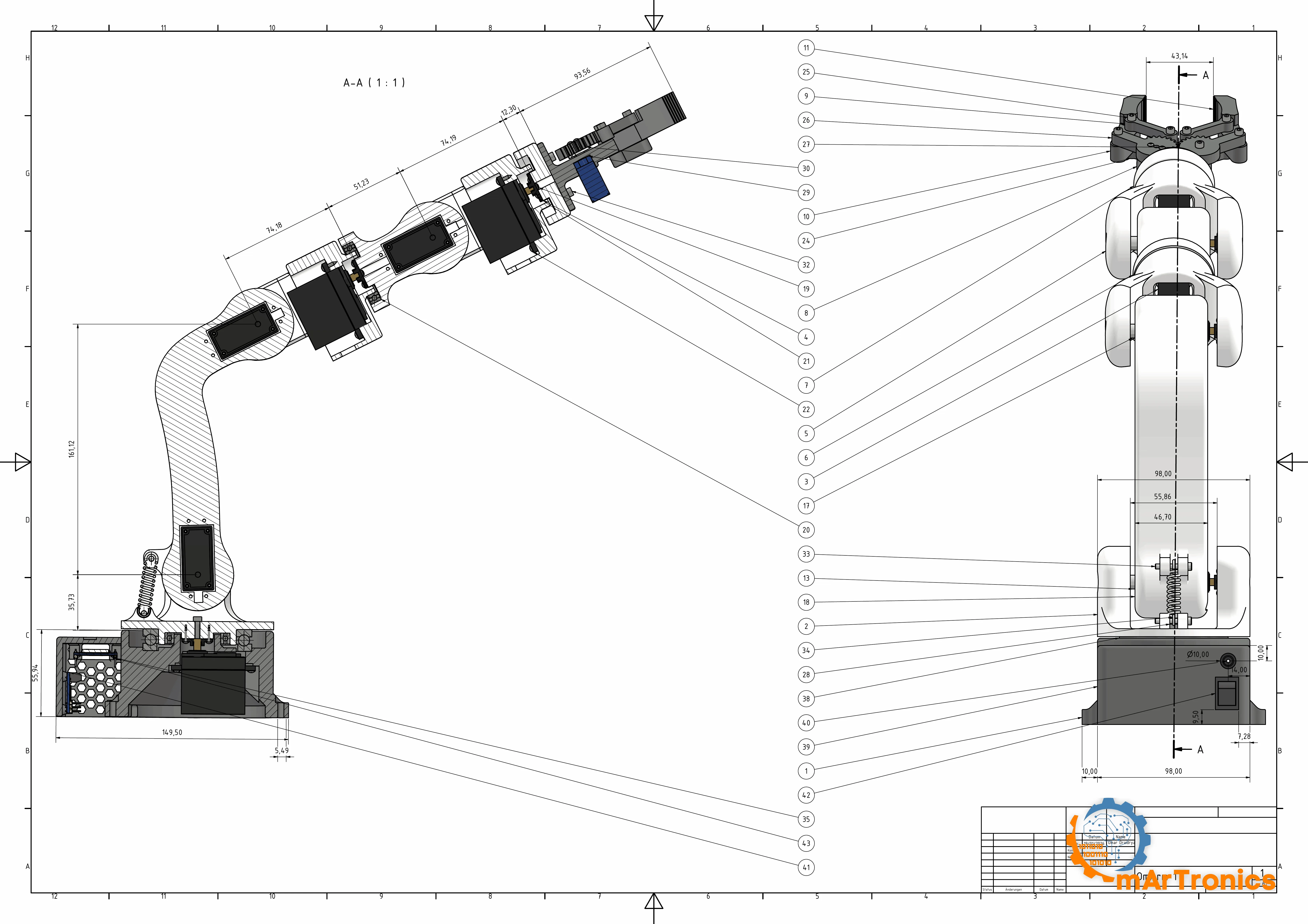
Complete parts list
The first column is the balloon number in the drawing above, taken from the Inventor assembly. The numbers are not in sequence, because Inventor numbers parts in the order they entered the assembly, and I did not renumber them. Point at a balloon, find the row. Position 23 is missing: the export lists it as fifteen “Document” entries, which are Inventor bookkeeping with no physical part behind them.
The prices in the shop table below are street prices as of August 2026, rounded and marked as approximate. They are what the parts cost to order today, not what my own build cost me. Mine came together over months and out of two boxes of leftovers, so an order total from it would be fiction.
Printed parts. Eighteen distinct bodies, 23 pieces. The two print plates hold 22 of them; base_link_upper is not on them yet, so print it from 02_base_link_upper.stl.
| # | Part | Qty | Role |
|---|---|---|---|
| 1 | base_link | 1 | Base housing: servo pocket, bearing seats, electronics bay |
| 2 | base_link_upper | 1 | Rotating platform on the bearings, carries the shoulder fork |
| 39 | base_link_AKL | 1 | Base cover plate |
| 18 | arm_link_1_2 | 1 | Upper arm, shoulder to elbow |
| 5 | arm_link_22 | 2 | One body printed twice, which is why the two 80.29 mm forearm segments in section 4 come out identical |
| 6 | arm_link_33 | 1 | Forearm segment, forearm roll to wrist pitch |
| 7 | arm_link_tool | 1 | Tool flange, carries the gripper |
| 36 | arm_link_cover | 1 | Servo bay cover on the arm |
| 8 | gripper_base | 1 | Gripper housing |
| 26 | gripper_gear_left | 1 | Driving gear |
| 27 | gripper_gear_right | 1 | Driven gear |
| 9 | gripper_link | 2 | Upper links of the jaw linkage |
| 24 | gripper_link_bottom | 2 | Lower links of the jaw linkage |
| 10 | gripper_part_left | 1 | Left jaw |
| 11 | gripper_part_right | 1 | Right jaw |
| 13 | sleeve_1 | 1 | Bearing spacer, one pitch joint. Ø 8.9 x 9.0 mm, 5.2 mm bore, measured from the STL |
| 17 | sleeve_2 | 2 | Bearing spacer, the other two pitch joints. Ø 8.9 x 8.0 mm, same 5.2 mm bore, per the drawing |
| 33 | pin | 2 | The two pins that hold the shoulder spring in its lugs |
| Total | 23 |
Bought, mechanical.
| # | Part | Qty | Spec | Source | Price |
|---|---|---|---|---|---|
| 3 | Joint servo J1 to J6 | 6 | DSSERVO DS3240-180, 36 kg·cm at 5 V, 40 x 20 x 40.5 mm, 25T spline. Read the note below about what the CAD calls this part | Buy | see shop table |
| 4 | Servo horn, 25T | 6 | Ships with the servo, one per DS3240. At J1 and J2 the aluminium horn in the next row replaces it, see section 10 | with servo | included |
| 4 | Aluminium round servo horn, 25T spline, for MG995/MG996-size servos | 2 | J1 (base) and J2 (shoulder). Bought separately, sold in packs of 5 | Buy | see shop table |
| 38 | 51110 axial thrust bearing | 1 | 50 x 70 x 14 mm, chrome steel, with washer. In the base, carries the arm’s weight | Buy | see shop table |
| 20 | 6806ZZ radial ball bearing | 2 | 30 x 42 x 7 mm. One in the base (tipping moment), one at J4 forearm roll | Buy | see shop table |
| 12 | 695ZZ miniature ball bearing | 3 | 5 x 13 x 4 mm. Loose side of the pitch joints J2, J3, J5. The drawing calls it 619/5, which is the same bearing under its ISO designation | Buy | see shop table |
| 34 | Extension spring | 1 | Shoulder assist: 13 N at 30 mm extension, 40 mm hole-to-hole at rest, wire 0.8 to 1.0 mm, outer Ø 8.5 to 10 mm (measured, see section 5) | Buy | see shop table |
| 29 | SG90 micro servo | 1 | Gripper drive, 9 g, analog | Buy | see shop table |
| 30 | SG90 horn | 1 | Ships with the servo | with servo | included |
Shoulder spring: section 5 has the Gutekunst Z-071I specification reference and the buying rule (13 N at 30 mm extension).
Fasteners: 86 pieces.
| # | Fastener | Qty | Where |
|---|---|---|---|
| 15 | Hex bolt M5 x 20, full thread | 2 | Pitch-joint bearing axles |
| 16 | Hex bolt M5 x 25, full thread | 1 | The third pitch-joint axle |
| 14 | Hex nut M5 | 3 | One against each of the three bolts above |
| 22 | Self-tapping pan head, #2 x 3/8″ (≈ M2.6 x 9.5) | 24 | Six servos, four screws each |
| 21 | Self-tapping pan head, #1 x 3/8″ (≈ M2.2 x 9.5) | 26 | Printed housings |
| 35 | Self-tapping pan head, #1 x 1/4″ (≈ M2.2 x 6.4) | 8 | Printed housings, where the wall is thinner |
| 19 | Self-tapping ISO 7049 ST2.2 x 4.5 | 5 | Boards and covers |
| 25 | Socket head ISO 4762 M3 x 25 | 4 | Jaw linkage |
| 28 | Socket head ISO 4762 M3 x 16 | 4 | Jaw linkage |
| 32 | Socket head ISO 4762 M3 x 8 | 4 | |
| 44 | Socket head ISO 4762 M3 x 10 | 2 | |
| 37 | Pozidriv AS 1427 M3 x 8 | 2 | |
| 31 | Pan head EN ISO 7045 M1.6 x 5 | 1 | SG90 horn |
Read the three M5 rows together: three bolts, three nuts, three sleeves, three miniature bearings. That one-to-one match is also the check against the wrong bearing size described below.
Which screw goes where. Quantities and designations come from the Inventor parts list; the locations come from the assembly animations in section 7, which is also where the step numbers point.
| Items | Fastener | Goes where | Step |
|---|---|---|---|
| 15, 16, 14 | 3 x M5 bolt + nut | Pitch-joint axles: the 25 mm bolt at the shoulder, the two 20 mm at elbow and wrist. The wrist bolt goes in at the end of step 10 and its nut at the start of step 11 | 6, 8, 10 |
| 22 | 24 x #2 self-tapping | Four at every DS3240. Six servos, four screws each, which is where all 24 go | 2, 5, 7, 11, 12 |
| 33, 34 | 2 pins + spring | The spring hangs between its two printed lugs on these pins | 6 |
| 19, 21, 35 | 39 cross-head pan heads in three lengths | Everything else printed: the two boards on the inner wall of the base, the servo horns to the links they drive (four per horn), and the base shell and its face. Match the length to the wall you are driving into, and drive them slowly: a self-tapper cuts its own thread in PLA and strips it as easily | 1, 4, 5, 6, 7, 8, 10, 12, 13 |
| 37 | 2 x Pozidriv M3 x 8 | Item 36, the dark cover strip on the upper arm | 5 |
| 44 | 2 x M3 x 10 | Item 39, the base cover | 1 |
| 32 | 4 x M3 x 8 socket head | Gripper base onto the tool flange | 15 |
| 25, 28 | 4 + 4 M3 socket head | The jaw linkage, long screws through the links, short into the gears | 16 |
| 31 | 1 x M1.6 x 5 | The SG90 horn | 16 |
Electronics.
| # | Part | Qty | Note | Price |
|---|---|---|---|---|
| 43 | ESP32-WROOM-32 DevKit | 1 | WiFi on board, USB serial for the ROS 2 serial firmware later | see shop table |
| 41 | PCA9685 driver board | 1 | 16 PWM channels, driven over I2C, a two-wire bus between chips | see shop table |
| 42 | Power switch | 1 | In the base housing face | see shop table |
| 40 | DC barrel jack, 5.5 x 2.1 mm | 1 | Screw terminals, in the base housing face | see shop table |
The electronics are Zero’s stack: ESP32, PCA9685 and one servo supply, here set to 6 V. It was never the limiting factor, and reusing it means everything the Zero series taught about wiring and firmware carries over.
Barrel jack: the Inventor parts list says 5.5 x 2.5 mm, while the schematic and the build use the far more common 5.5 x 2.1 mm. Use 2.1 mm. A 2.1 mm plug in a 2.5 mm socket makes intermittent contact on a rail that feeds seven servos.
Not in the assembly model, so these carry no balloon number:
| Part | Qty | Spec | Price |
|---|---|---|---|
| Power supply | 1 | 6 V; the build runs a HANMATEK HM305P bench supply set to 6.00 V (5 A limit); a fixed 6 V / 10 A power supply needs no adjustment | see shop table |
| Electrolytic capacitor | 1 | 1000 to 2200 µF across the servo rail | see shop table |
| M3 heat-set inserts | 8 | Brass, for the gripper linkage joints. They replace the nuts Zero used, and they are what ended its slow self-loosening | see shop table |
| Jumper wires | 1 set | ESP32 to PCA9685, servo leads | see shop table |
| PLA filament | 450 g | 421 g of model plus 28 g of support, see section 5 | see shop table |
| Total | ca. 210 to 360 €, see the shop table below |
Where to buy it
| Parts used in this project | AD · AFFILIATE LINKS |
|---|---|
| 6 x joint servo DSSERVO DS3240-180, 36 kg·cm at 5 V, 25T spline | Amazon* · AliExpress |
| 2 x aluminium round servo horn 25T spline, for MG995/MG996-size servos, at J1 and J2. Sold in packs of 5; not counted in the total | AliExpress |
| 1 x gripper servo SG90 micro servo, 9 g | Amazon* · AliExpress |
| 1 x 51110 axial thrust bearing 50 x 70 x 14 mm, with washer | Amazon* · AliExpress |
| 2 x 6806ZZ radial ball bearing 30 x 42 x 7 mm | Amazon* · AliExpress |
| 3 x 695ZZ miniature ball bearing 5 x 13 x 4 mm (the drawing calls it 619/5) | Amazon* · AliExpress |
| 1 x extension spring 13 N at 30 mm, 40 mm hole to hole. An assortment box is a low-cost option | Amazon* · AliExpress |
| 1 x ESP32-WROOM-32 DevKit 38 pin | Amazon* · AliExpress |
| 1 x PCA9685 16 channel I2C PWM servo driver | Amazon* · AliExpress |
| 1 x power supply 6 V, 10 A minimum, 20 A comfortable. The linked unit is adjustable: set it to 6.0 V and check it with a meter before you connect the servos | Amazon* · AliExpress |
| 1 x DC barrel jack 5.5 x 2.1 mm with screw terminals | Amazon* · AliExpress |
| 1 x rocker switch for the servo rail | Amazon* · AliExpress |
| 1 x electrolytic capacitor 1000 to 2200 µF, 16 V or higher | Amazon* · AliExpress |
| Servo extension leads and jumper wires | Amazon* · AliExpress |
| 3 x M5 hex bolt (2 x 20 mm, 1 x 25 mm) and 3 x M5 nut | Amazon* · AliExpress |
| 14 x M3 socket head screws (4 x 25, 4 x 16, 4 x 8, 2 x 10 mm) | Amazon* · AliExpress |
| 63 x self-tapping screws M2.2 and M2.6, plus 1 x M1.6 x 5 for the SG90 horn | Amazon* · AliExpress |
| 8 x M3 heat-set inserts brass, for the gripper linkage | Amazon* · AliExpress |
| 450 g PLA filament 1.75 mm | Amazon* · AliExpress |
*Affiliate links: I earn a small commission if you buy through them, at no extra cost to you.
As an Amazon Associate and AliExpress affiliate, OmArTronics earns from qualifying purchases. The price stays the same for you, and the small commission helps keep these tutorials free.
What the total means. 210 to 360 € is what you pay if you buy every part new, in whole packs. That means ten 695ZZ bearings for the three the arm needs, a spring assortment for one spring, and a kilo of PLA for 450 g. Count only the material that ends up inside the finished arm and the value is ca. 160 to 270 €. If you already own a printer, filament, a 6 V supply and a drawer of M3 hardware, the shopping list is ca. 140 to 250 €. All three numbers are dominated by the same row: six DS3240 servos, 40 to 43 % of the total. Depending on the shop and the shipping time, six cost between about 84 and 150 €. That one decision moves the total more than every other line put together.
Check two rows before you order: the joint servo is the DS3240 (the DS3218 looks identical), and the pitch-joint bearing is the 695ZZ (a 693ZZ does not fit the M5 bolt). The next subsection has the numbers.
Most links are search links. The 51110 and the aluminium horns link to the exact parts on my arm. The servos, the power supply and the M3 screw set link to one checked listing each, because a search for them returns wrong variants first. Individual listings disappear within months, while a search keeps working; match its results against the specs in the left column.
Three parts that look like the right one and are not
Each of these three parts sits next to the correct one in a shop listing and differs from it by a single number.
The bearing in the wrong size. The pitch-joint bearing is the 695ZZ, 5 x 13 x 4 mm; the assembly calls it 619/5, the same bearing under its ISO designation. The part to avoid is the 693ZZ, 3 x 8 x 4 mm. What settles it is the fastener list: three M5 bolts and three M5 nuts against three bearings and three sleeves, and an M5 bolt does not fit through a 3 mm bore.
The servo in the CAD is not the servo you buy. The assembly lists the joint servo as an MG996R. This arm cannot run on MG996R. Section 4‘s torque scan puts 23.60 kg·cm on the shoulder at the 250 g maximum. An MG996R stalls around 11 kg·cm on a 6 V rail, so it could not hold even the empty arm. The MG996R is a stand-in body from the CAD library, picked because it has the same standard servo footprint. The part to buy is the DS3240.
The servo you nearly order is not the servo either. DSSERVO sells the DS3218 and the DS3240 in the same case, with the same 25T spline and the same mounting flange. The DS3218 is a 20 kg·cm servo at 5 V, about 23 at 6 V. The DS3240 is 36 kg·cm at 5 V and 41 at 6 V. Section 4 put the shoulder requirement at 23.60 kg·cm, so on the standard 6 V rail the two servos land in different places.
| At 6 V | Stall | Sustained budget at 63 % | Shoulder needs, at the 250 g max | Margin |
|---|---|---|---|---|
| DS3240 | 41 kg·cm | 25.83 kg·cm | 23.60 kg·cm | +2.23 kg·cm |
| DS3218 | 23 kg·cm | 14.49 kg·cm | 23.60 kg·cm | −9.11 kg·cm |
On a DS3218 the shoulder cannot hold the arm’s own weight within a duty cycle it survives: 14.49 kg·cm of budget is already less than the 16.10 the empty arm needs. No rail voltage saves it. If you own DS3218s already, this arm needs different geometry, not a firmware change.
That substitution left one dimension to worry about: the DS3240 is 0.3 mm wider than the stand-in body, and width is the dimension a printed pocket holds tightest. On the built arm the pockets take the DS3240, so the CAD’s clearance absorbs the difference.
Bearing selection: why these three
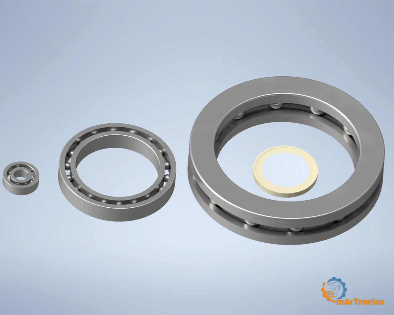
Three bearing types for seven joints, and the reasoning for each one is in section 5. Two points belong here. ZZ means metal shields on both sides. They keep print dust out of the races, which matters on a machine that stands next to a 3D printer. And the case against plain bushings is arithmetic. A tenth of a millimetre of play across the 60 mm shoulder fork is 0.1 degrees of tilt, and 0.1 degrees at 485 mm is 0.8 mm at the fingertips.
Servo selection: the DS3240, and what “40 kg” means
The joint servo is the DSSERVO DS3240-180, and the first point to sort out is the big number printed on its side.
The case says 40 kg. The datasheet’s own spec table has only two voltage columns: 36 kg·cm at 5 V and 45 kg·cm at 6.8 V. Interpolate between those two points and you land at 41 kg·cm at 6 V, and the datasheet’s product description is, word for word, “6V 40kg RC Digital Servo”. The 40 is the 6 V figure, rounded down. It is real, quoted at a voltage the spec table never lists, and it is not what you get at 5 V.
| Rail voltage | Stall torque | No-load speed | Stall current | Shoulder at 23.60 kg·cm |
|---|---|---|---|---|
| 5.0 V | 36 kg·cm | 0.20 s/60° = 300 °/s | 3.10 A | 65.6 % of stall, over the line |
| 6.0 V, standard | 41 kg·cm | 0.183 s/60° = 327 °/s | 3.54 A | 57.6 % of stall |
| 6.8 V | 45 kg·cm | 0.17 s/60° = 353 °/s | 3.90 A | 52.4 % of stall |
5 V and 6.8 V are datasheet rows; the 6 V line is linear interpolation between them.
The utilisation and payload figures in section 4 use the 6 V row, because 6 V is the standard rail. A sagging supply drops the servos toward the 5 V row, which the payload table lists separately. The rail cannot go higher: the SG90 gripper shares it and is rated for 6 V at most. That 6 V limit is also the voltage at which the joint servos deliver their advertised 40 kg.
The similar model names confused me too. Between near-identical DS3218 and DS3240 listings I spent a while convinced I owned the other model. Check the model number against the datasheet PDF before you order.
The datasheet values that decided the choice:
Stall torque 36 kg·cm at 5 V, 41 at 6 V. Section 4 needs a servo rated at least 37.5 kg·cm at the shoulder, which is above the 5 V figure and inside the 6 V figure; that is why the arm runs on 6 V. One class down, the 18 to 24 kg·cm bracket, would put the shoulder past 100 percent at useful payloads. One class up costs more, weighs more, and adds torque the printed structure cannot use.
Dead band 3 µs. Over the 500 to 2500 microsecond range mapping to 180 degrees, 3 µs equals 0.27 degrees, the resolution limit of the arm. The pen test in section 10 measures the repeatability you get on top of it. For scale, 0.27 degrees at the base is about 2.3 mm at the fingertip at full reach.
Speed 0.20 s/60° at 5 V, which is 300 degrees per second unloaded. The firmware never runs the joints that fast, and each software layer above the servo sets its speed margin against this datasheet ceiling.
Stall current 3.1 A at 5 V (3.9 A at 6.8 V). The power budget in section 4 starts from this figure.
The mechanical rest: 342:1 metal gear train, double-bearing output shaft, IP66 sealed case, 60 g, 25T output spline, and an accepted update rate of 50 to 330 Hz. IP66 means dust-tight and protected against water jets. The update rate turns into a wiring decision below.
Section 4 explains why the same servo sits at all six joints.
The gripper servo, and why it rewired the electronics
The gripper runs an SG90: 9 grams, analog, the same micro servo Zero used. The two gripper gears are the same size and mesh 1:1, so the pair keeps both jaws moving together and does not multiply the servo’s force. The SG90 still held the 325 g of the payload test in section 10.
The SG90 is analog and accepts only 50 Hz, while the six DS3240 run at 250 Hz on the PCA9685 (section 8 explains why). One board runs one frequency, so the gripper gets its own 50 Hz timer on an ESP32 pin: six joints on the PCA9685 at 250 Hz, one gripper on its own pin at 50 Hz.
ESP32 and PCA9685
Both come from Zero; the Zero post has the long version. The ESP32 brings WiFi, enough compute for a web server alongside a motion loop, and a USB serial port for the ROS 2 serial firmware later. The PCA9685 exists because PWM generated in dedicated hardware does not jitter when WiFi interrupts fire. You set a pulse width over I2C and it holds it. Driving all six servos this way takes only the two I2C wires from the ESP32.
Both boards live inside the base housing, so there is no breadboard hanging off the back of this arm.
Power supply sizing
Section 4 did the math: about 4.3 A in typical motion, and the crash case only with every joint blocked. A 6 V 10 A supply covers everything you would call operation, and the 1000 to 2200 µF capacitor absorbs the transients.
The rail voltage follows from the SG90’s 6 V ceiling. The shared rail stays at 6 V even though the DS3240s would take 6.8 V and deliver 45 kg·cm there. That costs the joint servos their top 4 kg·cm. In return the arm needs one rail, no second supply and no level shifter (a circuit that converts a signal from one voltage level to another).
The supply on my bench is a HANMATEK HM305P, a small programmable unit set to 6.00 V, and its 5 A current limit is below the 10 A this section recommends. It works anyway, for two reasons. The motion core’s speed caps keep the arm’s typical draw around 4.3 A. When a move does ask for more, the supply switches to constant-current mode: it holds the current at its limit and lets the voltage sag, so nothing burns. That sag moves the joints toward the 5 V column of the payload table. For a permanent installation a fixed 6 V / 10 A power supply is the better choice; the bench supply’s advantage is the display.
The KCD1 rocker switch and the 5.5 x 2.1 mm barrel jack in the base are rated about 6 A and 5 A. That covers the bench setup above, which limits the current to 5 A. Switch the servo rail only while the arm is at rest. If your supply delivers more than 6 A, use a switch rated 15 A DC or more, and wire the supply directly to the PCA9685 screw terminal instead of the jack.

7. Assembly guide
The sequence below is the one the CAD assembly plays back: you start with the box the arm stands on, because the electronics have to go in before the base is closed.

Before you start
A stalled joint servo presses with its full 41 kg·cm on the 6 V rail. Across the whole 485 mm to the fingertips that is a modest 0.85 kg of force. Three centimetres from a joint axis, which is about where a finger gets caught, the same stall is roughly 14 kg of clamping force. Nothing here is lethal and none of it needs protective equipment, but the arm can hurt you at close range, so follow five habits from the first screw on.
- Keep your fingers out of the joint gaps while the servos are powered. The forks close on themselves, and a servo does not notice an obstruction.
- Switch the servo rail off while you work on the arm. The switch in the servo + line does that, and the ESP32 keeps running on USB, so the web page stays up while nothing can drive. Switch it back on with the arm where the firmware last left it, or with your hands clear.
- Clear the table before you first enable the servos. By design the arm does not move on boot, so the movement to plan for is the first one after output is enabled.
- Hands clear before you confirm a pose. After a power cycle or an upload the firmware asks where the arm is. Whatever you answer, it switches the servos on at those angles. Section 8 has the mechanism.
- The danger is the current. Six volts will not hurt you. Ten to twenty amps into a shorted servo lead is a burn and a smoke hazard, so check polarity before the switch goes on and keep bare ends apart.
And one rule that saves you a part:
Centre every servo electrically before you put a horn on it. Wire the servo, power the board, command 90 degrees, and only then push the horn on at the angle the CAD wants. A servo mounted at the wrong horn angle loses part of its travel at one end and hits its mechanical stop at the other. On my build I used 0 degrees instead of 90. With the loose servos on the driver board as the schematic shows, I set them all to 0 in the web app from section 9. An angle of 0 degrees is the end of each joint’s travel, where the joint starts, so each horn went on with its joint at that end. Either way, check which way each servo turns before its horn goes on.
Every one of the sixteen steps below has a CAD animation of the operation. Each is a short loop that shows the part going in from your working angle, and the order they play in is the order to build in.
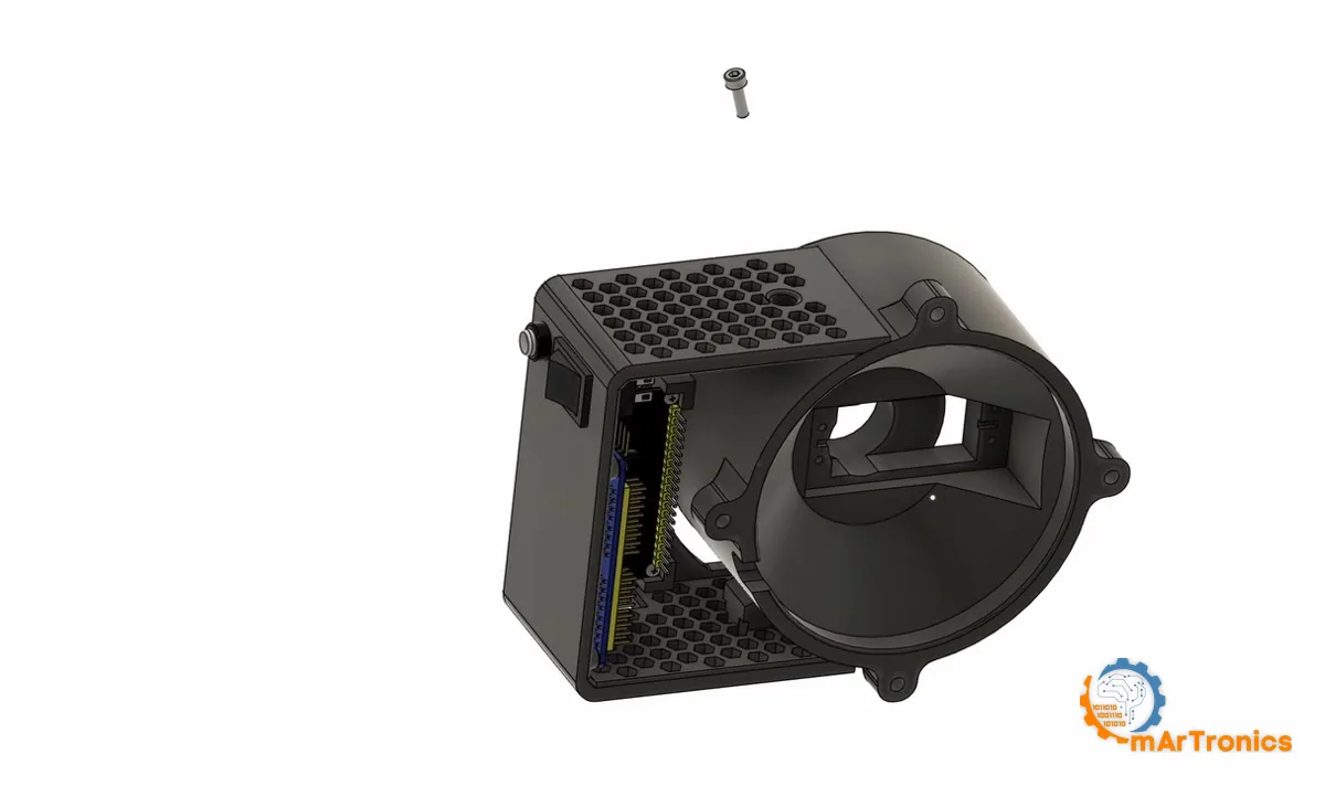
Step 1: Electronics into the base housing

Wire everything before you close anything up. I wire the base first because, once the rotating platform is on, the electronics bay can only be reached by taking the arm apart. Section 8 has the wiring in detail; do that first and come back here.
Step 2: The base servo

Screw it down, but leave the horn off. The horn goes on in step 4, after the servo has been centred electrically, which is the rule at the top of this section.

Step 3: The two base bearings

Check both seats with a caliper before you press anything. FDM bores often print undersize. A 42 mm seat that came out at 41.7 will not take a 6806ZZ. Forcing it splits the print along a layer line, usually while you are leaning on it with a vise, at a moment when you cannot stop.

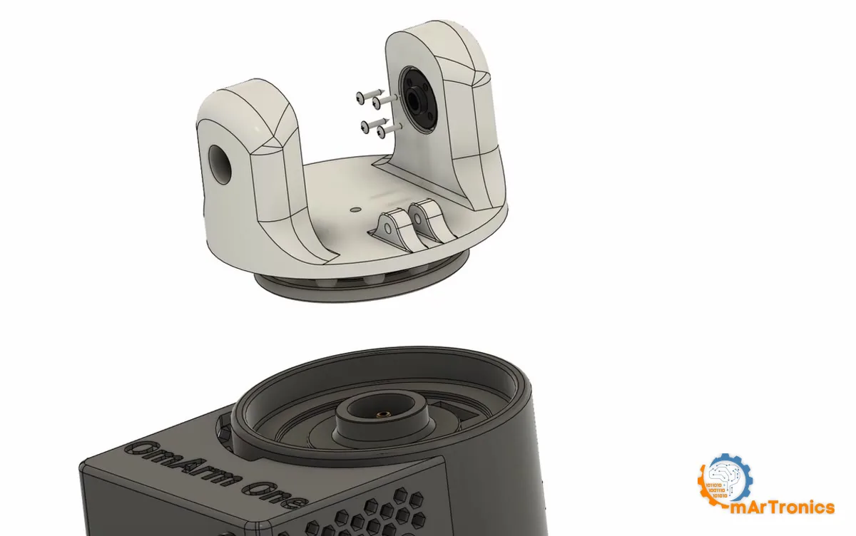
Step 4: Platform onto base

From this step on, the platform rotates on steel bearings. Grab the assembled base and try to rock it: the bearing ring resists you. On Zero, the servo spline took that load.

Step 5: The upper arm, on the bench

This one link carries two servos, one at each end: J2 drives the shoulder below it and J3 drives the elbow above it. Both horns point outward, so both joints close later against parts that are already on the machine.
This step is the one I had in the wrong place for a long time, and the animation is what corrected it. Build the upper arm complete first. Once it is hanging in the shoulder fork you are working one-handed, over a base that wants to tip, with a screwdriver you cannot get square to the screw.

Step 6: The shoulder, and the spring

The platform carries a two-armed fork with a plain bore in each arm and no servo pocket in either: the J2 servo went into the upper arm in step 5. Press the 695ZZ into one fork arm, drop the finished upper arm between the arms, and screw the horn to the opposite fork arm. Then slide the sleeve through the bearing and run the M5 x 25 in with its nut on the outside; the shoulder gets the long bolt of the three.
Tighten until the arm swings freely under its own weight with no side play. That combination, free but not loose, is how a fixed-loose arrangement is supposed to feel. If the joint stiffens as you tighten, your sleeve is too short and the fork arms are being pulled inward.


The spring closes this step. Hook it between the two printed lugs, one on the platform and one on the upper arm, and pin both ends. It pulls the arm up.
Step 7: The roll-joint pattern

This is the second of the two patterns, and from here on the arm is these two repeating. A roll joint has no fork and no loose side. The servo sits in the segment, the horn goes on its spline, and the next segment screws straight onto the horn.


Step 8: The elbow closes

Same rule as the shoulder. Tighten until the joint is free but has no side play, and stop when it stiffens.
Step 9: The forearm roll, bearing and horn

This is J4, and it is the only joint outside the base that gets a 6806ZZ; section 5 explains why.
Step 10: The forearm roll segment onto the arm

Slide the segment over the horn, run the four screws in, and check that the roll turns freely before you move on. The M5 goes in from the side at the end of this step; its nut waits for the next one. This is also the last easy moment to route the wrist cables through the segment, so do that now, before step 12.
Step 11: The wrist servo

That nut is the third and last of the three M5 sets, and it closes the bolt you drove in at the end of step 10. Centre the servo before the horn goes on. Every joint from here out is close enough to its mechanical limits that a horn one spline tooth off costs you visible travel.
Step 12: The wrist pitch joint

This is the last of the six DS3240 servos, and here the fork carries the servo body itself. Four screws hold it, the same as everywhere else. Centre it before the horn goes on, and check that the joint swings freely before the next step closes access to these screws.
Step 13: Closing the wrist

Once this screw is in, the wrist is a closed unit. Run all three wrist joints by hand through their travel once; anything that rubs now would take two steps of disassembly to fix later.
Step 14: The tool flange

J6 is the exception here. It runs on the servo horn alone, with no bearing; section 5 has the numbers.
Step 15: The gripper base

Four M3 socket heads through the base into the flange. Snug is enough; the printed threads strip before the screws do.
Step 16: The gripper

Close the jaws by hand before you mount the servo horn, so you know which way the gear pair travels, then centre the servo and set the horn at the fully open position.
After the sixteen steps: cable routing
Seven servo cables have to reach the base without getting pinched at a joint or pulled tight at full extension. Run them along the inside of the links and leave a service loop (a loop of spare cable that lets the joint move without pulling on it) at every joint. Check the whole range of every joint by hand before power goes anywhere near the arm.
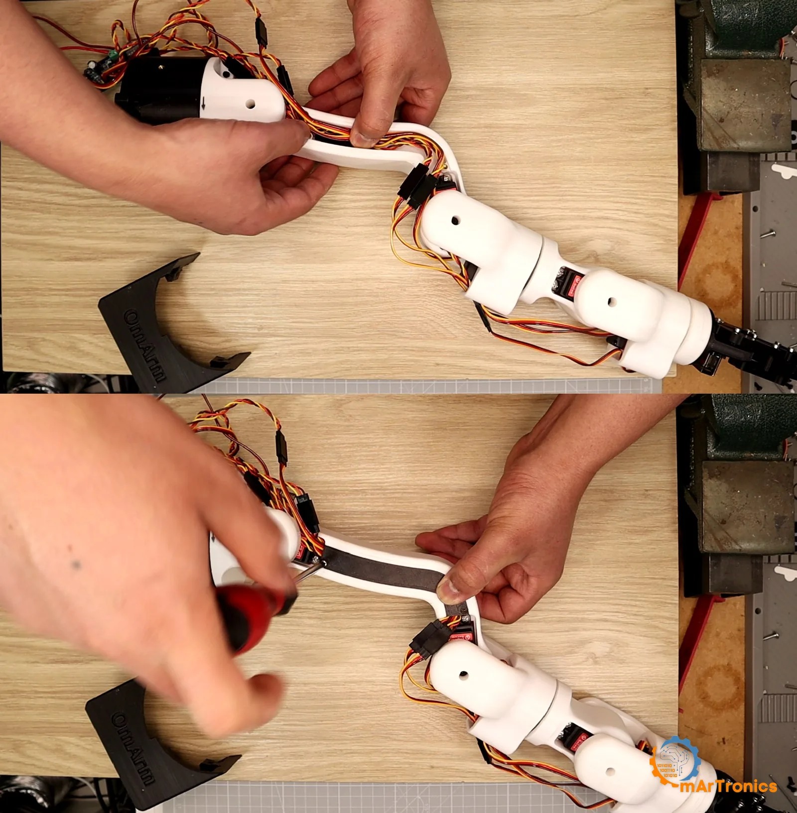
Every fastener in these sixteen steps is itemised in section 6, including a which-screw-goes-where table keyed to the drawing’s balloon numbers. Two parts are missing there, because the assembly model does not carry them: the M3 heat-set inserts in the gripper linkage, and the two small screws that come in the SG90’s own bag.
8. Wiring and first power-up
Two circuits, and the wiring is mostly about keeping them apart. A signal path runs from the ESP32 to the servos, and a power path runs from the supply to the servos without touching the ESP32.
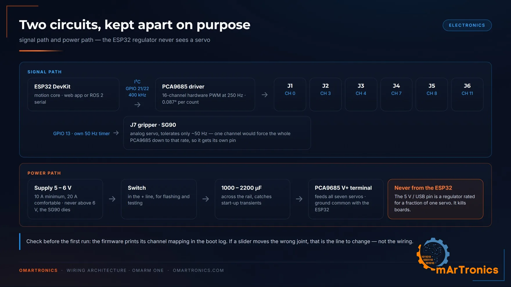
The connections

| From | To | Note |
|---|---|---|
| ESP32 GPIO 21 (SDA) | PCA9685 SDA | I2C at 400 kHz |
| ESP32 GPIO 22 (SCL) | PCA9685 SCL | |
| ESP32 3V3 | PCA9685 VCC | logic supply for the driver chip only |
| ESP32 GND | PCA9685 GND | common ground, required |
| ESP32 GPIO 13 | SG90 signal | own 50 Hz timer, not on the PCA9685 |
| Supply + (6 V) | PCA9685 V+ screw terminal | plus 1000 to 2200 µF across it |
| Supply − | PCA9685 GND screw terminal | |
| SG90 + / − | servo rail | the V+/GND pins of PCA9685 channel header 12 |
| Switch | in the servo + line | use it while flashing and testing |
| USB | ESP32 | the only supply for the ESP32 |
The arm runs on two supplies, and they are easy to mix up. The 6 V supply powers the servos and nothing else. The ESP32 is powered over USB, and it in turn feeds the PCA9685’s logic pin from its 3V3 rail. Unplug the USB and everything is dead even with the 6 V connected. Switch off the 6 V and the ESP32 still boots and still serves the web page, but nothing moves. That second state is useful, and the first power-up below runs in it.
The ESP32’s VIN or 5V pin is not a power source for servos. On a USB-powered DevKit it is fed from the USB supply, which delivers a fraction of one servo’s stall current.
Channel assignment
The firmware expects J1 to J6 on PCA9685 channels 0, 3, 4, 7, 8 and 11. I spread the servos across the header to leave room for the connectors and keep the wiring readable.
| Joint | J1 | J2 | J3 | J4 | J5 | J6 | J7 |
|---|---|---|---|---|---|---|---|
| Channel | 0 | 3 | 4 | 7 | 8 | 11 | ESP32 GPIO 13 |
The same six numbers appear in the sketch as SERVO_CHANNELS[] = {0, 3, 4, 7, 8, 11}, and they match the drawing above net for net. The firmware also prints the mapping in its boot log, so you can read back what it thinks is connected. If a slider moves the wrong joint, change that line and leave the wiring alone. The sketch says as much in its own header comment.
Checked on the built arm: the harness follows the schematic, and the boot log’s channel map matches what the sliders move.
The 250 Hz decision, and the trap inside it
The PCA9685 drives the six joint servos at 250 Hz, well inside the DS3240’s 50 to 330 Hz window. Five times the classic rate takes one count of the PWM register from 0.44 degrees at the joint down to 0.086. Since the servo’s own dead band is 0.27 degrees, at 250 Hz the servo’s dead band sets the resolution limit.
Now the trap. The PCA9685 does not run at the frequency you ask for. It divides its internal oscillator by an integer prescaler:
f = osc / (4096 × (prescale + 1))
At 50 Hz the rounding error is 0.06 percent and nobody notices. At 250 Hz the nearest prescaler is 23, which gives 254.3 Hz, 1.7 percent off. The chip therefore runs a shorter period than you asked for, so pulse counts computed from the nominal 250 Hz come out 1.7 percent short. The result is a gain error that grows across the travel: 0.8 degrees at one end of the travel, 2.3 in the middle and 3.8 at the other end, on every axis. The 0.086 degrees per count above comes from that same 254.3 Hz: an exact 250 Hz would give 0.088, and the extra 4.3 Hz accounts for the last two thousandths of a degree. I therefore compute every count from the prescaler that is in the chip, never from the frequency I asked for. If you write your own control code, copy that habit.
First power-up
Install the two libraries the sketch needs (Adafruit PWM Servo Driver Library, ArduinoJson), flash it, and leave the servo power switch off for the first boot. Watch the serial log: it prints the channel mapping, the real PCA9685 frequency, and whether the gripper timer attached.
Then join the WiFi access point OmArmOne (password omarmcontrol) and open http://10.10.10.1. The web app is carried inside the sketch and writes itself to the ESP32’s filesystem on first boot, so there is nothing else to upload.
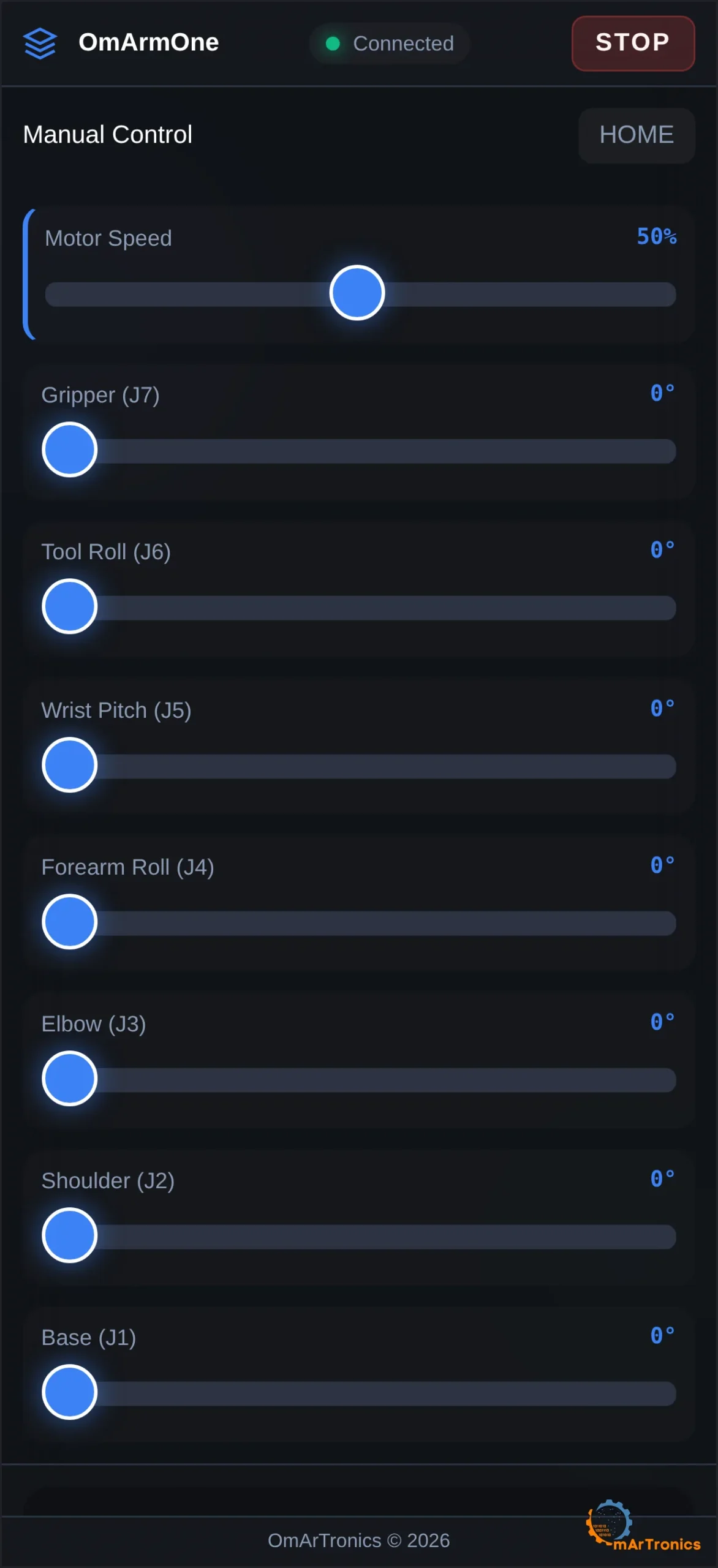
The part that matters on a machine this heavy is what happens after a reset. The arm has no position feedback, so the firmware wakes up with no idea where it is. The naive behaviour, and what my own earlier version of this code did, is to drive every joint to zero at full speed on boot. On an arm this heavy, that makes every upload a crush hazard. Instead:
- Two records hold the pose. A copy in RTC memory (a small memory block that keeps its content through a CPU reset) is refreshed on every servo tick, which keeps a reset in the middle of a move safe. A flash copy is written a moment after the arm comes to rest. RTC memory survives a CPU reset and not a power cycle, which is the same line the reset-reason logic draws.
- After a software reset or a crash the firmware restores that pose and re-commands the servos exactly where they already stand, so nothing moves.
- After a power-on, a brownout (a supply dip deep enough to reset the chip) or an upload, it drives nothing at all. The web app raises a warning and waits for you to declare the pose. An upload lands here because it resets the board through the EN pin (the ESP32’s reset input), which the chip reports as a power-on. Fold the arm in or support it before you flash.
- Declaring the pose is a jump, not a move. Both confirm buttons, and a SETPOS command over USB with the ROS 2 serial firmware, switch the servos on at the angles you declare, at once. If the arm is not there, it snaps to them at full speed. The four-second rule below applies to the first commanded move, not to this. Hands clear.
- The first move after any boot is forced to take at least four seconds, no matter where the speed slider sits.
- The emergency stop freezes the arm with the servos still holding, and it latches; section 9 has the release flow.

Two quirks on the servo side of a reset:
- The gripper hangs on GPIO 13, so during a reset it stops receiving pulses and goes limp (no holding torque). Empty the jaws before you flash.
- J1 to J6 keep their PCA9685 pulse through the reset itself, but the sketch then parks every channel full off before it touches the driver. The chip’s registers survive a reset holding counts computed for the previous frame rate, and re-running them would snap a joint toward its stop. No pulse is the safe intermediate state. The six channels come back only once the firmware accepts a pose, so in the confirm-first case they stay limp until you answer. The rail is still live; only the pulse is missing.
None of this replaces the switch in the servo power line. Use it.
9. The web interface
Join OmArmOne, then open http://10.10.10.1. Type the http:// or the phone will treat it as a search term. No app, account or internet connection is needed, so the arm also works in a workshop without mobile signal or in a classroom where installing software is not allowed.
One warning first, because it will otherwise cost you ten minutes. Phones treat a network with no internet behind it as suspect. Android asks whether you want to stay connected and can start routing traffic over mobile data instead, and iOS marks the network as having no connection. If the page stops answering for no visible reason, that is usually the cause. Turn mobile data off while you drive the arm, or answer the prompt when it appears.
What you are looking at
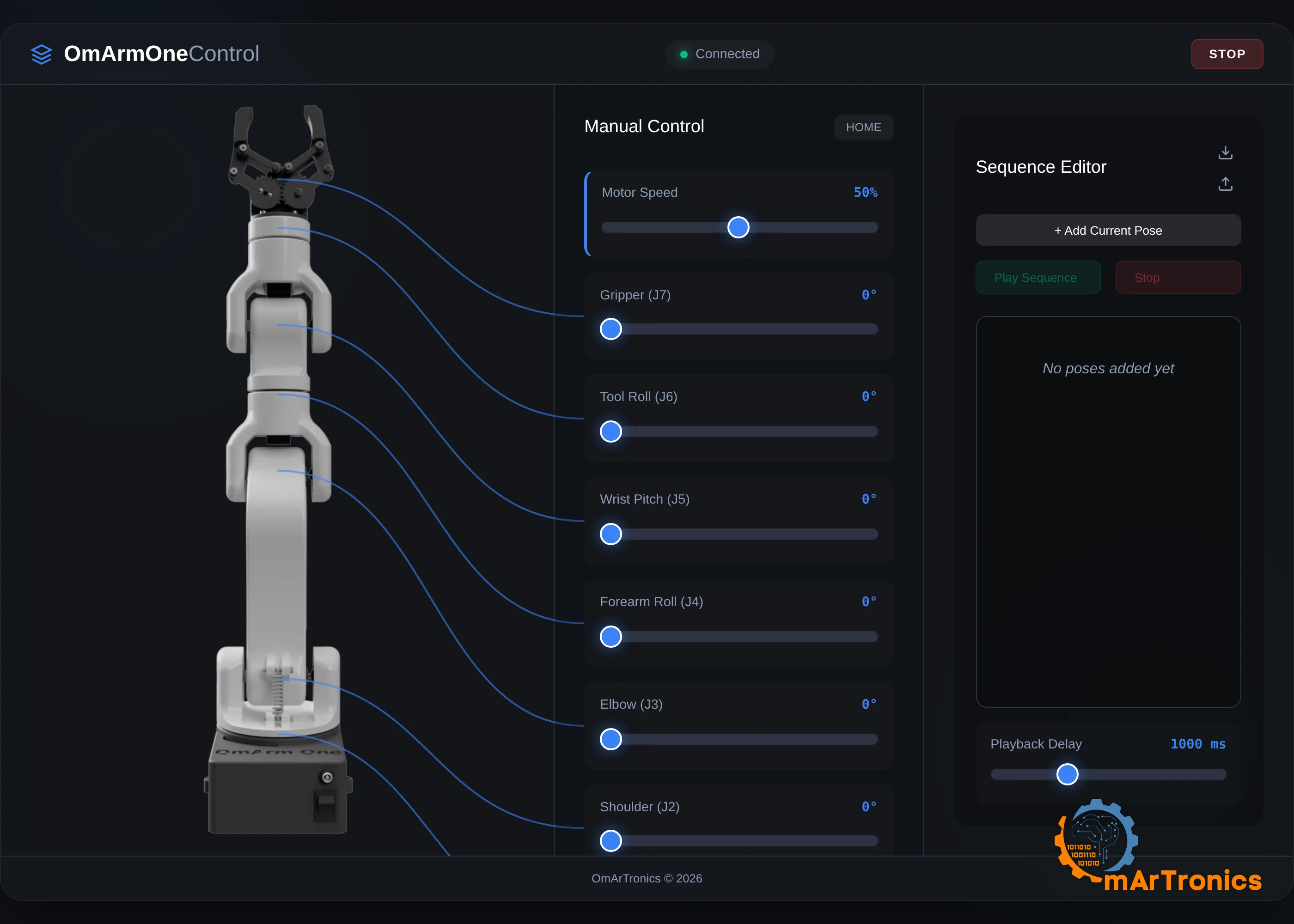
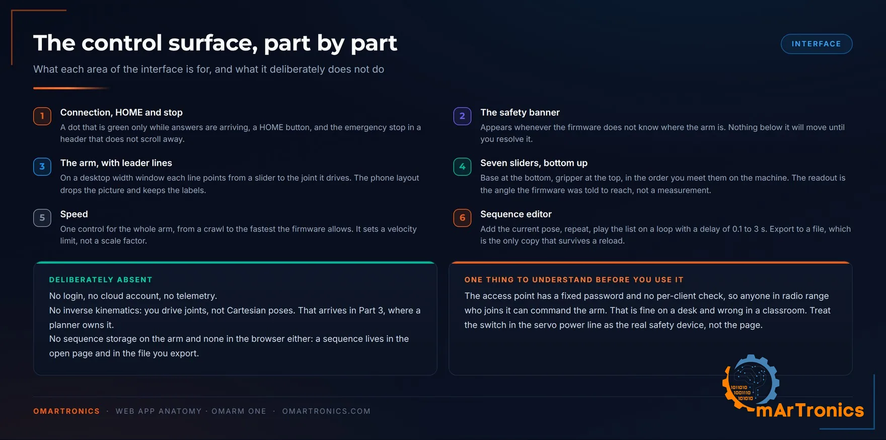
Seven sliders run bottom to top in the order you meet the joints on the machine. J1 base, J2 shoulder, J3 elbow, J4 forearm roll, J5 wrist pitch, J6 tool roll, and J7 the gripper at the top.
The number in each label is the angle the firmware was told to reach. Nothing on this arm measures an angle, so nothing on this page can show you one. Whether the servo arrived is a separate question, and section 10‘s repeatability check is how you answer it on your own machine.
In a window wider than 1024 pixels each slider is tied to a picture of the arm by a leader line. Anything narrower, a phone or a desktop window snapped to half the screen, drops the picture and keeps the labels.
Three controls sit above the sliders. A connection dot goes green only when a reply arrives, though it is not a heartbeat: a request that hangs leaves it green until the browser gives up. “HOME” runs a coordinated move to J1 0, J2 45, J3 45, J4 0, J5 0, J6 0, J7 61, which is where the arm should be parked. The emergency stop “STOP” sits in the page header, and the header is the one part of the layout that never scrolls, so it stays within reach wherever you scroll.
One speed slider governs the whole arm. It runs 1 to 100 percent, which the page turns into a velocity ceiling of 15 to 180 degrees per second and an acceleration ceiling four times that. Those two numbers go to the firmware, which enforces them inside its own control loop, so a slow setting stays slow even if the page freezes mid-drag.
The sliders set joint angles only. I left inverse kinematics out of this interface. Cartesian control (commanding a position in space) arrives in Part 3, where a planner owns it and can check a path for collisions before anything moves. A half-working version in a browser would have been worse than none.
What happens during a slider drag
Skip this if you only want to drive the arm. It matters if you want to change the interface or write your own client.

Each slider covers 0 to 180 degrees in whole steps, so it fires an event on every degree your finger crosses. Sending all of them would overload a microcontroller that is also feeding the servo driver 250 times a second. The page therefore sends the first value at once, then at most one every 50 milliseconds, and values in between overwrite each other. On release it sends the final value once more, because a lift inside one of those 50 millisecond windows would otherwise leave the arm a few degrees short. The label updates on every degree regardless, so the number tracks your finger even while the requests lag behind it.
In the other direction the page asks for STATUS every two seconds and gets the whole machine state back as one JSON object. It holds the seven angles, the pose that was in flash at boot, and whether a planned move is running. It also reports whether the position is known and confirmed, whether the emergency stop is latched, the I2C error count, and how many servo ticks arrived late. The page displays only a few of them. The rest are there for a terminal or a script, and for debugging a joint that stutters.
Every command is one line of text. It travels to /api/command inside a one-field JSON body, {“cmd”:”HOME”}, and the answer comes back as JSON. MOVE:0,45,45,0,0,0,61 is a coordinated move in which all seven joints share one duration and arrive together. 4,120 sends joint 4 to 120 degrees on its own. The ROS 2 serial firmware uses the same one-line grammar over USB from Part 3 on, into the same motion code.
The position-confirm banner
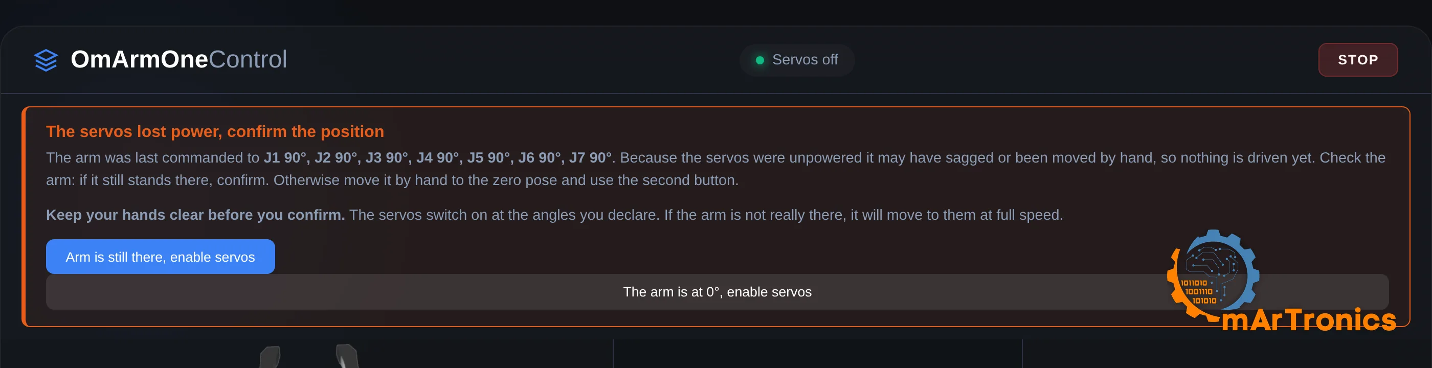
There are two ways this arm refuses to move. A red banner across the top of the page means the firmware does not know where the arm is and wants you to tell it. No banner and nothing happening means the emergency stop is latched, and the fix is the “Release the stop” button. In both cases the sliders still slide and the numbers still change, because nothing greys them out. The refusal happens in the firmware, and the reason appears in the status line for a few seconds.
Section 8 explains why the firmware refuses (reset reasons, RTC memory, flash pose). This section shows what you see in the browser. Printed in the banner is the pose that was in flash when the firmware came up. You hold that list of angles against the arm in front of you and decide which of the two buttons underneath is telling the truth.
The button “Arm is still there, enable servos” claims that the arm stands where the firmware left it. The button “The arm is at 0°, enable servos” claims you have wound every joint by hand to its 0 degree end, gripper included. That second pose is the one you can hit accurately by hand, because every joint runs into a hard stop there. It is not the “HOME” pose, which parks the shoulder and elbow at 45 degrees.
Both buttons switch the servos on at the angles they name, so a wrong claim makes the arm jump to them at full speed. That is why each button arms on the first tap and only fires on the second, and why the warning above them says to keep your hands clear. It is also why they are labelled with the claim you are making.
The emergency stop works the other way round. Pressing “STOP” freezes the arm with the servos still powered and still holding, because cutting drive to an arm this heavy would drop it. Then it latches, and the firmware refuses every motion command, including ones already on their way, until you press “Release the stop”. A value can already be sitting behind the 50 millisecond throttle when you hit the button, and a second phone on the same network knows nothing about your stop.
If the arm is doing something dangerous and the page is not answering, the switch in the servo power line is the last resort. It takes the holding torque with it, so the arm falls. Clear whatever is underneath before you reach for it, and reach for the on-screen stop first.
The sequence editor
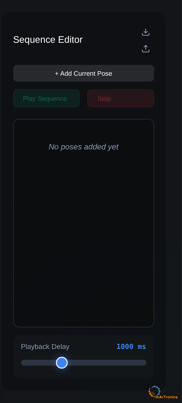
Set the arm to a pose, press “+ Add Current Pose”, repeat. Press “Play Sequence” and it walks the list with a delay you pick between 0.1 and 3 seconds, reaches the end, and starts again from the top until you press “Stop”. That “Stop” is the same emergency stop as the one in the header, latch and release included.
This is a minimal form of teaching by demonstration: you record poses by hand, and the arm replays them.
The list lives in the open page and nowhere else. Reload the tab and it is gone. “Export” writes it to omarm_one_sequence.json, which is the only copy that survives, and “Import” reads it back. A six-value sequence from OmArm Zero imports as well: J1 to J5 map straight across, Zero’s gripper becomes J7, and the new tool roll starts at 0. None of it is stored on the ESP32. The firmware has no sequence command and only knows how to go to a pose.
How the page gets onto your phone
Skip this if you only want to drive the arm. It matters if you want to change the interface.
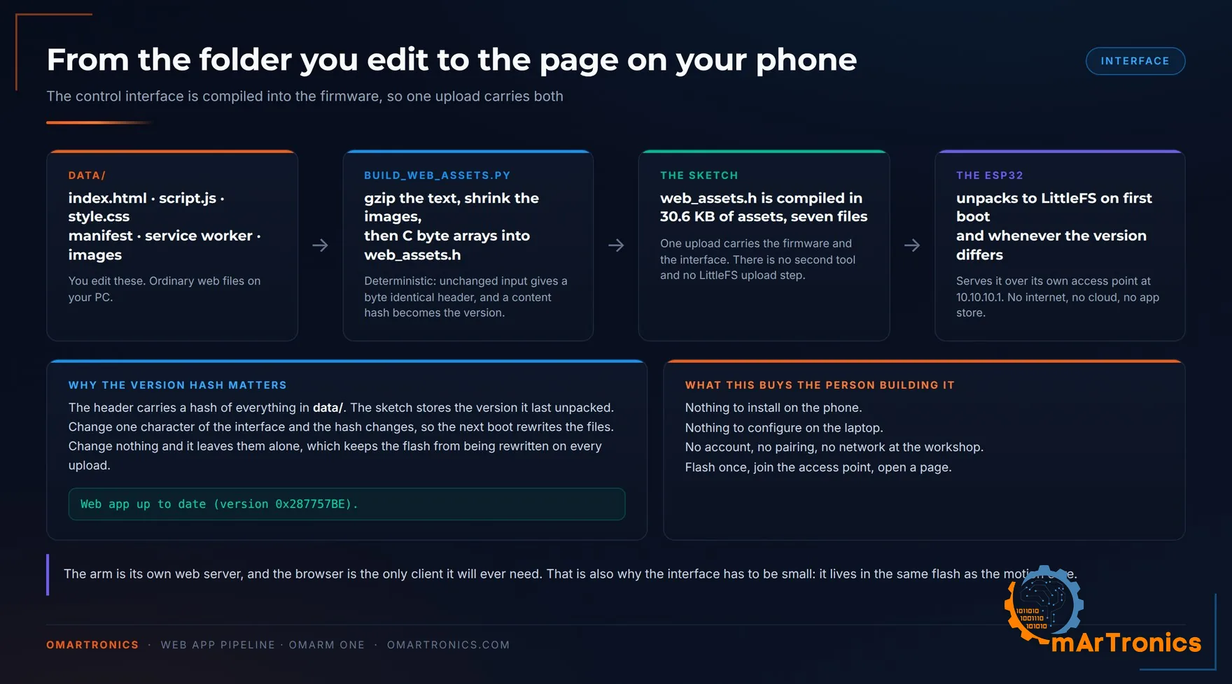
The interface is seven ordinary files in data/, next to the Arduino sketch: one HTML page, one script, one stylesheet, a manifest, a service worker and two images. The script build_web_assets.py turns them into web_assets.h, a C header file that the compiler builds into the firmware. It gzips the text files, shrinks the two PNGs to a 255 colour palette and stores each file as a C byte array. On first boot the sketch unpacks them onto the ESP32’s filesystem and serves them from there.
Compiled, the whole sketch lands at 1,058,099 bytes, 80 percent of the ESP32’s 1.25 MB app partition. The packed interface accounts for 31 KB of it: 12.4 KB of gzipped text and 18.2 KB of PNGs.
The version check is the part I would keep in any project like this. web_assets.h carries a hash of everything in data/, and the sketch remembers the hash it last unpacked. Change one character of the interface and the hash changes, so the next boot rewrites the files. Change nothing and it leaves the flash alone.
Web app up to date (version 0x287757BE).
That line in the boot log means the page in your browser matches the firmware behind it. It also removes the separate filesystem upload step.
Security limits
The access point has a fixed password compiled into the sketch, and /api/command has no authentication of any kind. Anyone in radio range who joins the network can command the arm. Cross-origin requests (requests that a page loaded from another site sends to the arm) are allowed too. Any page already open in a connected browser can therefore post commands to the arm as well. On a desk that is fine. In a room full of people it is not, so change the password before you take this arm anywhere public, and keep the servo power switch within reach of whoever is standing closest.
Outbound there is nothing at all. The interface loads no CDN, no font host and no analytics endpoint, which is why it works with the arm sitting on a bench in a basement. There would be no internet on that network to reach anyway.
10. Testing and validation
Five checks, in the order I would run them. The first one tests the payload specification.
The payload test
I computed the payload envelope before the build so that this test would have a prediction to fail against. Section 4 predicts the following.
| Test | Radius | Predicted sustained, 6 V | At stall | 5 V for comparison |
|---|---|---|---|---|
| Nominal check | 300 mm | 325 g | 830 g | 219 g |
| Maximum check | 300 mm | the 250 g maximum uses 57.6 % of stall | n/a | would need 65.6 %, over the line |
| Maximum edge | 370 mm | 252 g | 661 g | 167 g |
| Full stretch | 485 mm | 175 g | 488 g | 110 g |
Procedure. Mark the working radius on the table, measured horizontally from the base axis. Weigh the test object on a kitchen scale, note the measured mass, and do not round in your favour. Command the arm to a pose that puts the grasp point on the mark with the arm well stretched, close the gripper, and lift. Then leave it there for sixty seconds and touch the shoulder servo’s case. Warm is expected. If you cannot keep a finger on the case, the joint is over the sustained line whatever the arm is holding. An infrared thermometer turns that into a number you can write down.

What counts as a pass: the arm lifts the mass, holds the pose without sagging, and the shoulder servo case is still touchable after a minute. Sag under load is the interesting failure, because it means either the servo is past its torque budget or a bearing seat is loose. Those two feel different. Torque sag is smooth and continuous; a loose bearing gives you a step, a click, or a pose that drifts when you nudge the arm sideways.
Measured on my arm: 325 g held at 300 mm, the full predicted value, and the shoulder servo did not get hot. One part needed rework. The plastic horn at the shoulder wore its spline teeth away, and the joint began to slip. The shoulder and the base now run aluminium 25T horns, listed in the shop table in section 6.
Optional comparison at 5 V: same masses, same radii. Expect about a third less payload (219 g against 325 g at 300 mm). At 5 V the 250 g maximum needs 65.6 % of stall and fails the 63 % rule. Section 6 explains why the rail stops at 6 V.
Four more checks before you call it finished
Range per joint. Drive each joint slowly across its range with the arm supported, and approach both ends carefully. The 0 degree end is not free space: there the arm folds against its own mechanical stops, and the firmware will command that, because its only limits are the servo’s full 0 to 180. So the pass criterion is that each joint travels smoothly up to its first contact, not that it sweeps a clear 0 to 180. Stop at the first contact, back off, and note the angle. Compare it against the CAD: a joint that stops well short of its drawn limit usually has its horn one spline tooth off.
Repeatability. Mount a pen in the gripper, tape paper to the table under it, and teach one pose with the pen tip touching. Then alternate: drive to HOME, back to the pose, take the dot; drive to a second pose on the far side of the workspace, back, dot. Ten dots per direction, measured in the plane of the paper only. The servo’s dead band puts a floor of 0.27 degrees under the result, which is a Ø 2.3 mm circle at full reach. A cluster that size is the arm performing at its physical limit. A cluster much wider than that is mechanics: a loose sleeve, a bearing not fully seated, or a horn screw backing out. Two separated clusters, one per approach direction, are backlash. Measured on my arm: ten approaches from each side landed inside the Ø 2.3 mm floor, all of them driven from the web app.

Base stiffness. This test checks the base bearings, and the push direction matters. Clamp or weight the base to the bench first, extend the arm horizontally, then press down on the wrist with about 5 N, roughly a full 500 g can, and watch the fingertip. Down loads the 51110 and the 6806ZZ, because a vertical force at reach is a tipping moment about the base. Release, and the deflection should be elastic and return to zero. A rocking motion with a dead zone in the middle means a bearing is not fully seated or the platform is loose on the thrust washer.
Pushing sideways tests something else. That direction runs through J1’s gear train, where a little backlash is normal and says nothing about the bearings.
Weight. 1283 g on the kitchen scale, about 80 g above the component build-up in section 5 (about 1.20 kg). The analysis script uses the measured value, and every torque and payload figure stands.
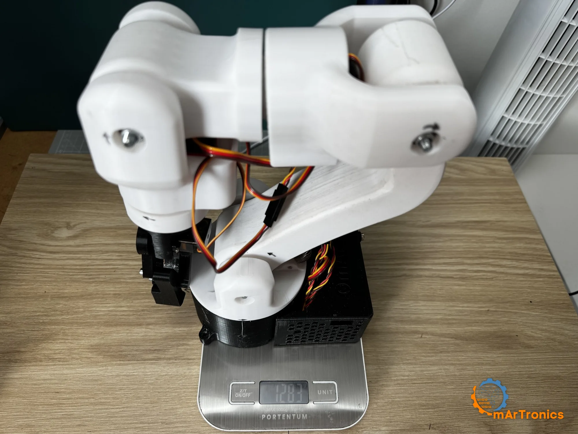
The build video at the top shows these runs.
11. Troubleshooting
These symptoms come from Zero’s build and from bringing this firmware up on the bench.
Every joint is off by up to 11 degrees, consistently. Your PCA9685 oscillator constant is wrong. Many example sketches set 27 MHz; the chip’s datasheet says 25 MHz. Feed 27 MHz to a chip running at 25 and every pulse stretches by 8 percent, which lands 1500 microseconds at 1620 and puts the joint 11 degrees off. Use 25 MHz unless you have measured your own board.
All joints slightly off and the zero point shifted. Prescaler rounding, described in section 8. Compute pulse counts from the prescaler in the chip (254.3 Hz at a 250 Hz request), not from the frequency you asked for.
The wrong joint moves when you drag a slider. Channel mapping, not wiring. Fix the SERVO_CHANNELS line, reflash.
Joints jitter or hum while holding still. Two causes. If the twitch is on all joints, it is PWM jitter: generate the signal on the PCA9685’s own hardware instead of on interrupt-driven GPIO, which is why the driver board is in the BOM. If a single joint hums, it is usually mechanical: a sleeve tightened until the fork binds, or a horn screw catching.
The whole arm goes limp at the end of a flash, and stays limp until you confirm the pose. Expected: an upload counts as a power loss. Section 8 has the full sequence, and why you fold the arm in and empty the gripper first.
Nothing moves at all on a brand-new board. Also expected: the firmware refuses to guess. Confirm the pose with one of the two banner buttons in the web app; section 9 shows the banner. With the ROS 2 serial firmware, send SETPOS over USB instead.
The arm moves sluggishly and the ESP32 reboots under load. Supply sag: undersized power supply, missing bulk capacitor, or servo power taken from the ESP32. A 10 A supply and 1000 to 2200 µF across the rail fix the first two; the third one you fix by rewiring, and the table in section 8 shows how.
The ESP32 gets hot, the USB port on your PC disappears, and the arm twitches on its own. Overvoltage on the servo rail. The DS3240 tolerates 6.8 V, the SG90 6 V, the PCA9685’s V+ 6 V, so eight volts is outside all three. The PC shutting down its USB port is a protection circuit doing its job. Section 4 has the incident. Check the rail with a meter before every session, and put a switch in the servo line so the first power-up after a wiring change is a conscious step.
A joint stalls near one end of travel. Servo horn one spline tooth off, or a printed part interfering. Recentre the servo electrically, remount the horn.
A bearing will not go into its seat. Measure the bore. FDM bores print undersize; the fix is a dimensional test print and a scaling tweak in the slicer. Step 3 in section 7 is where that caliper check belongs.
12. FAQ
Can I use cheaper servos, like the DS3218 or an MG996R? No. The shoulder needs 37.5 kg·cm of stall torque, and section 6 shows that a DS3218 misses even the empty arm’s 16.10 kg·cm within the 63 percent rule. An MG996R at 11 kg·cm is far too weak. On AliExpress the DS3218 is barely cheaper than the DS3240 anyway, roughly 82 € against 84 € for six, so the swap saves about two euro and costs you the shoulder joint.
Should I run 5 V or 6 V? 6 V. It is the standard rail, because the 250 g maximum needs the DS3240’s 41 kg·cm at 6 V. Do not go higher: the SG90 on the same rail is rated for 6 V at most.
Do I need the spring? No. Every number in this post was computed without it; section 5 explains what it adds.
Do I need ROS 2 to use this arm? Not for this part. The ESP32 serves its own web app over its own access point, so a phone or laptop is enough. ROS 2 arrives in Part 2 with the digital twin and drives the real arm from Part 3 on, over the same USB port and the same firmware conventions.
Can it lift 500 grams? Not sustainably. At a 300 mm radius the stall ceiling is 830 g on the 6 V rail, and at stall a servo overheats. 500 g for a photo, briefly, yes. As a working payload, no; that is a different machine.
My printer is not a Bambu P1S. Can I still print this arm? Any printer with a bed around 256 mm and decent dimensional accuracy will do. Check bore accuracy before printing the base, since the bearing seats are the only truly critical dimensions in the whole model.
13. What comes next
Part 2 is out. It exports the CAD to URDF and checks the digital twin against the real arm in RViz and Gazebo (Gazebo Harmonic on ROS 2 Jazzy), without flashing new firmware. Part 3 adds the hardware driver and MoveIt 2 planning, Part 4 camera-guided pick and place, and Part 5 grasping named objects without markers.
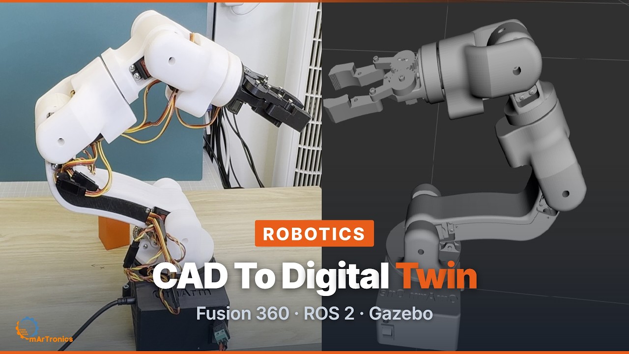
Read it: From Fusion 360 to a ROS 2 Digital Twin · Download the workspace: OmArm One Digital Twin package.
If you build one or find an error in the numbers, open an issue in the GitHub repository. The analysis script that produced them is seeded and reproducible.
Resources
- Build package: OmArm One package (39 € launch price until 30 Nov 2026, then 49 €): CAD, print files, firmware and the PDF guides for Part 1 and Part 1.5. The product page has the full list.
- Firmware, analysis script and tests (MIT): github.com/OmArTronics/OmArm-One. It holds the web-app and ROS 2 serial firmware with their PC-side tests, and the wiring diagrams. The script omarm_one_analysis.py re-runs the sizing on the CAD-derived robot model, so you can verify every figure in this post. The CAD is in the package above.
- Spring measurement and substitute selection: spring-rate-measurement.md in the repository.
- OmArm Zero, the predecessor series: Part 1.
All my robot arms compared: How to build a 6-axis robot arm at home explains what 6-axis means, puts the four designs in one table and tells you which one to build first.