
This post contains affiliate links, marked with *. As an Amazon Associate I earn from qualifying purchases, at no extra cost to you. It helps keep the tutorials free.
OmArm One Series
- Part 1: Build, statics and payload.
- Part 1.5: Drive it with a game controller (this post).
- Part 2: Digital twin, URDF in RViz and Gazebo.
- Part 3: MoveIt 2 and ros2_control on real hardware (video).
- Part 4: Computer vision pick and place (coming soon).
- Part 5: AI: grasping by name, by voice (coming soon).
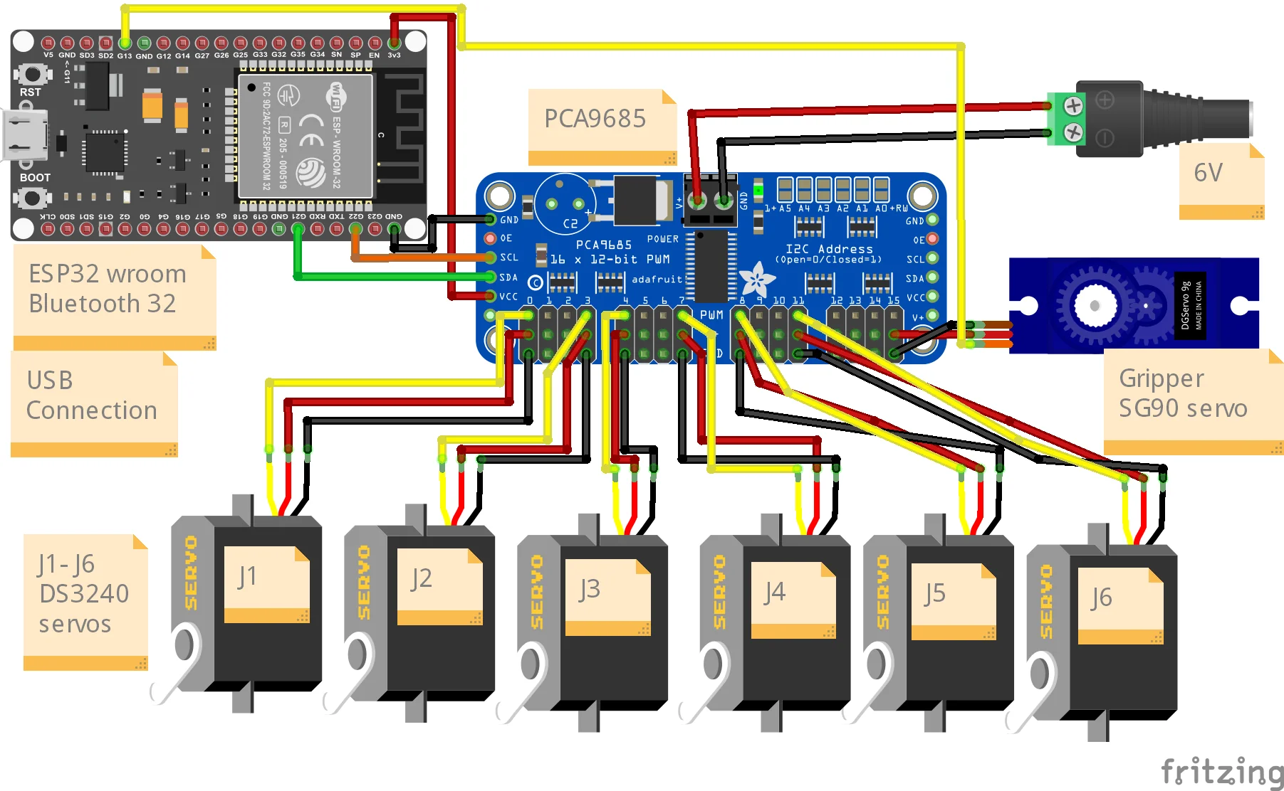
This is a bonus chapter between the build and the digital twin. You need a finished OmArm One from Part 1 (or any arm with the same ESP32 + PCA9685 servo driver electronics) and a Bluetooth game controller. There is no new wiring.
The video loads from YouTube (Google), which may set cookies. Privacy policy
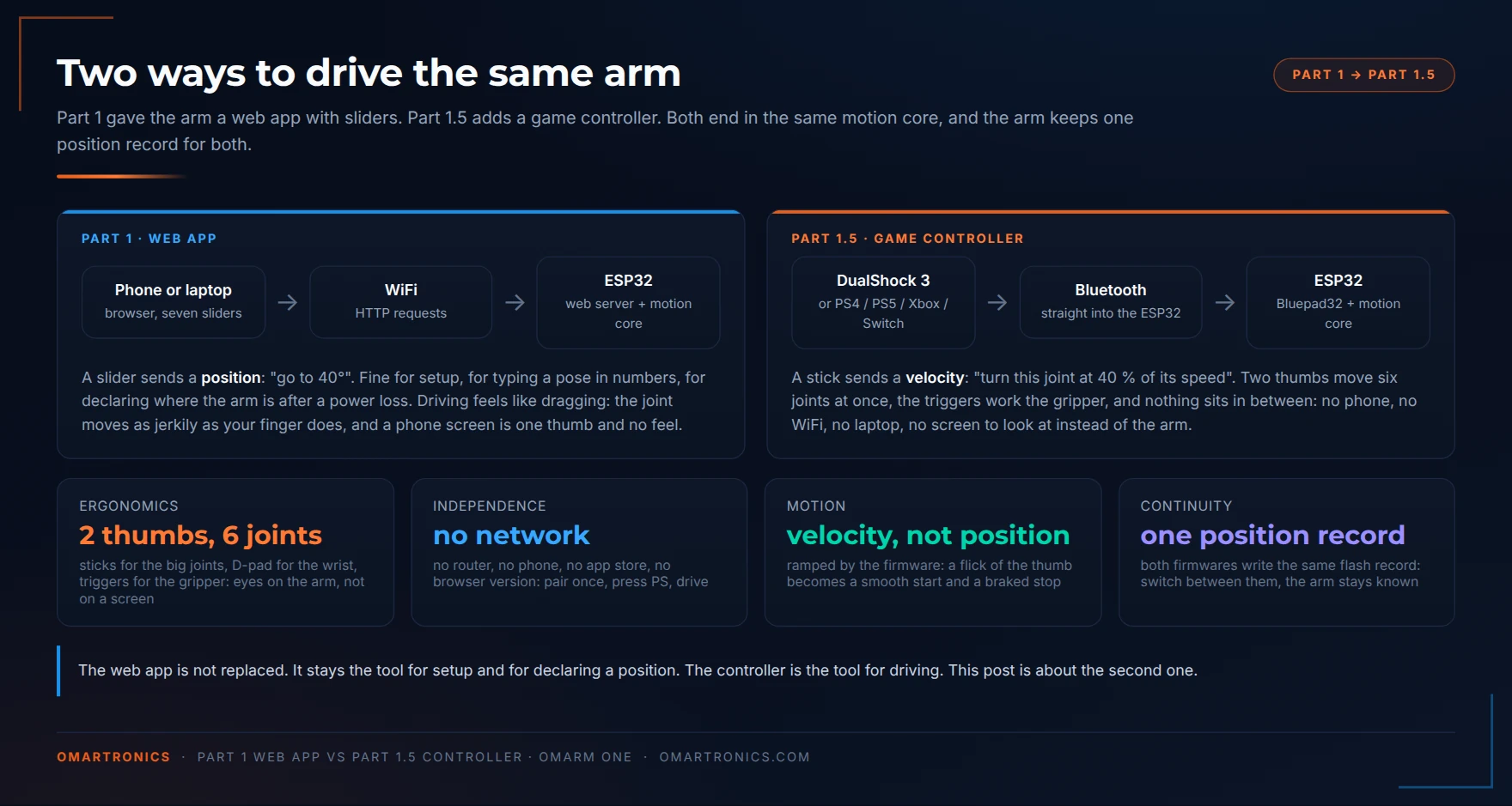
In Part 1 the arm got a web app. The ESP32 in the base brings up its own WiFi network, you open a page on your phone, and seven sliders move the six joints and the gripper. That is the right tool for setting the arm up: you see numbers, you can type a pose, and you can tell the firmware where the arm stands after a power cut. It is the wrong tool for driving. A slider sets a position: you drag it and the joint follows your finger. You watch the screen instead of the arm, one thumb moves one joint at a time, and when the phone’s screen locks, you lose control of the arm.
A game controller avoids these problems. A stick sets a velocity: push a little and the joint turns slowly, push more and it turns faster, let go and it brakes. The two sticks move four joints at the same time, the D-pad moves the two wrist joints, R1 and R2 work the gripper, and you keep your eyes on the arm. Because the controller talks to the ESP32 directly over Bluetooth, nothing else has to be switched on while you drive: no phone, no laptop.
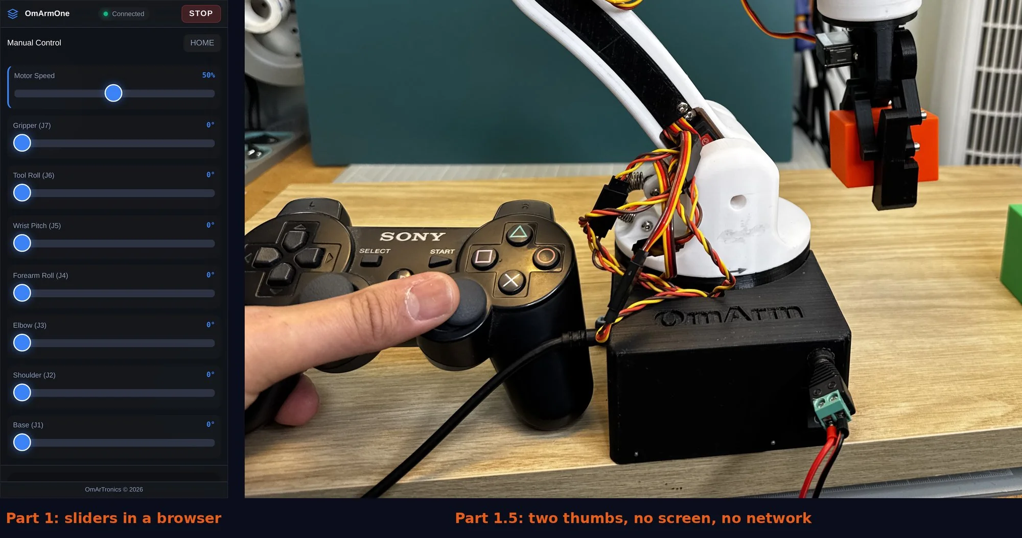
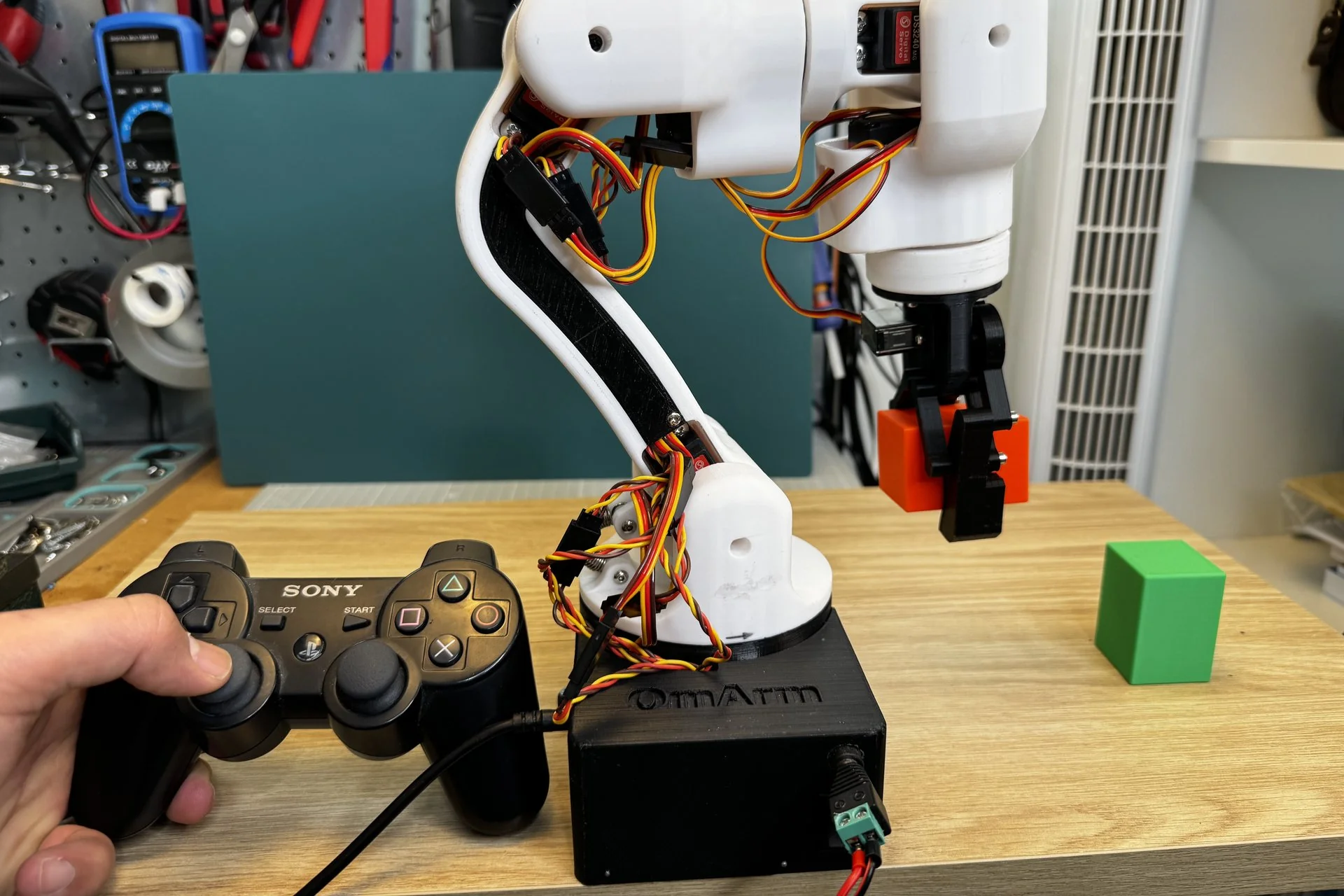
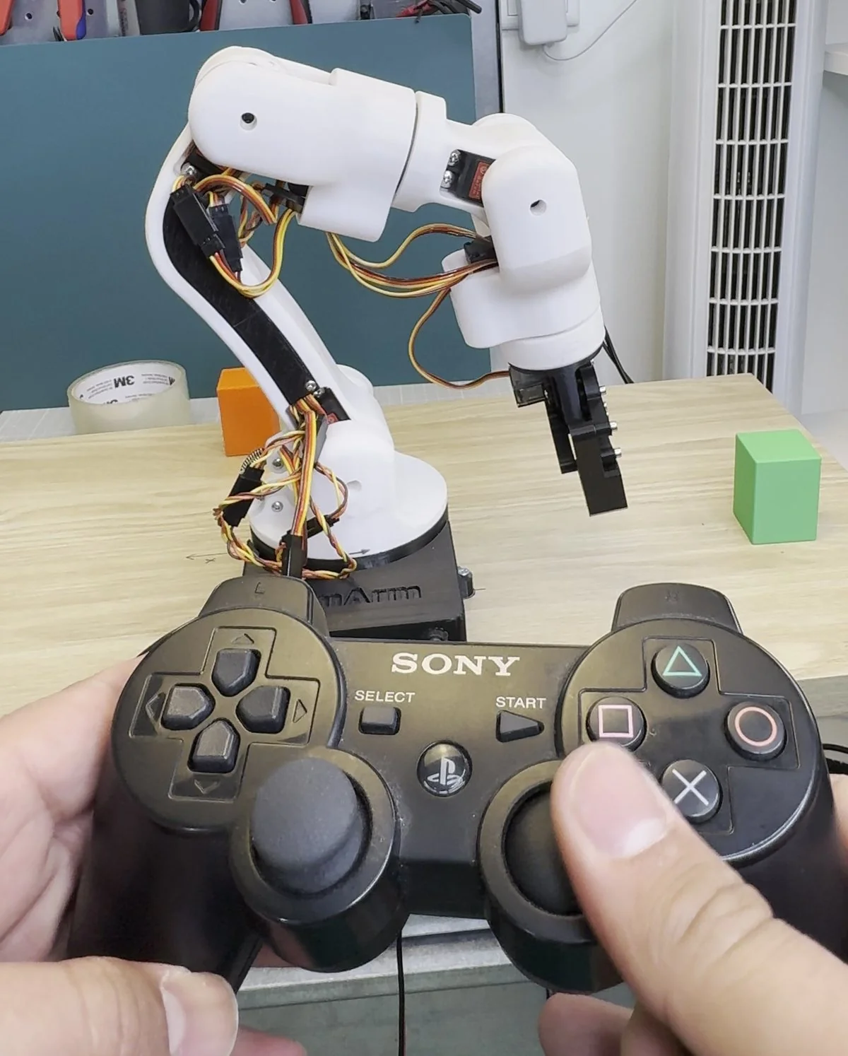
The controller in the photos is a PlayStation 3 DualShock 3, because I had one in a drawer. The firmware also works with other controllers: PS4, PS5, Xbox, Switch Pro and most third-party controllers run with the same code and the same mapping. Only the DualShock 3 needs an extra pairing step, and that step gets its own section.
At a glance
What you’ll build: A second firmware for the ESP32 in your arm. Flash it (upload it to the ESP32), pair a controller, and drive all six joints and the gripper with the sticks, the D-pad and the shoulder buttons. The firmware has four speed levels and an analog gas pedal on the L2 trigger. It also has a home button and a sequence of up to 16 poses that you record with one tap and play in a loop. The PS button is an emergency stop that latches: the arm stays frozen until you press Select. Each stick sets a joint speed (velocity control). A dead zone (a small range around the stick centre that is ignored), an expo curve (finer control near the centre) and a fixed braking rate shape the motion.
What you’ll learn: why a stick commands speed instead of position, which controllers and ESP32 variants work, how to pair a DualShock 3, and which safety rules the firmware enforces.
Time required: One evening. Ten minutes to install the board package and flash, ten to pair, the rest is driving.
Total cost: 0 € if you own a controller. A used DualShock 3 costs 10 to 20 €; make sure it is a real one (section 1), because most clones do not pair.
Difficulty: Easy, if Part 1 is done.
Safety: The arm moves faster under a stick than it ever did under a slider. The PS button freezes it instantly, and the first four seconds of motion after every start are capped at 15 % speed. The firmware does not move the arm until its position is known. Keep the servo power switch from Part 1 within reach of your free hand.
What you need: a finished OmArm One from Part 1, or any arm on the same ESP32 DevKit and PCA9685 electronics. A Bluetooth game controller from the table in section 1. A USB cable and the Arduino IDE. For a DualShock 3, also a PC for the one-time pairing step. No new parts, no new wiring.
Files you’ll need: the OmArmOne_Gamepad firmware and, optionally, the mapper tool. Both are in the GitHub repository linked at the end and in the complete package, which now carries this part next to Part 1 and includes a printable PDF of this guide.
1. Which controller do you have?
The model decides how the controller pairs. Turn the controller over and read the label.
| Controller | How to tell | Works? | Pairing |
|---|---|---|---|
| PlayStation 2 DualShock 2 | grey plug on a cable, no USB port, no LEDs | No | has no Bluetooth at all |
| PlayStation 3 DualShock 3 / Sixaxis | model CECHZC2E (EU), CECHZC2U (US), CECHZC2J (JP) on the back label; mini-USB port, four LEDs | Yes (the one in the photos) | the ESP32’s address is written into the controller once, section 4 |
| PlayStation 4 DualShock 4 | CUH-ZCT1 / ZCT2, light bar, micro-USB | Yes | hold Share + PS until the light bar blinks |
| PlayStation 5 DualSense | CFI-ZCT1, USB-C | Yes | hold Create + PS until the light bar blinks |
| Xbox One S / Series X|S | model 1708 or 1914, Bluetooth logo near the pair button | Yes | hold the pair button on the top edge |
| Xbox One (2013, model 1537 / 1697) | no Bluetooth logo | No | uses Xbox Wireless, not Bluetooth |
| Nintendo Switch Pro / Joy-Con | Pro: model HAC-013, USB-C, sync button on the top edge | Yes | hold the sync button until the LEDs run |
| 8BitDo and other third party | check the box for “Switch” or “Xbox” mode | mostly | start in Switch mode (Y + Start on most 8BitDo controllers; check the manual) or Xbox mode |
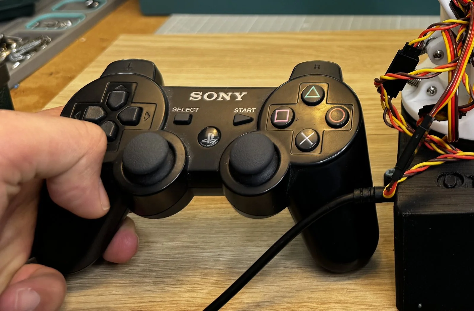
Two more checks on a DualShock 3 before you start. The battery must hold a charge; a controller that only works on the cable has a dead battery, and there is no cable mode here. And it must not be paired to a PS3 that is switched on in the same room, because the console connects to it first.
2. How it works, and why the ESP32 gets its own firmware
A game controller is a Bluetooth HID (Human Interface Device), the same device class as a wireless keyboard. To talk to one, the ESP32 needs a Bluetooth stack (the software that handles the radio protocol) that speaks HID and knows the quirks of each controller family. Bluepad32 is an open-source project that provides it. It supports every Bluetooth controller in the table above and presents all of them to your sketch (your Arduino program) as one abstract layout. That layout has two sticks, two triggers, four face buttons, two shoulder buttons, a D-pad and three system buttons. Your code never sees a PlayStation or an Xbox. It sees “right stick X” and “button A”.
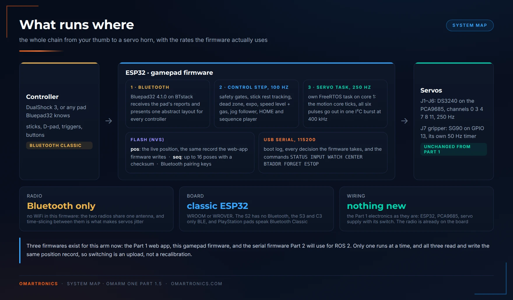
Bluepad32 swaps the ESP32’s Bluetooth stack for its own, which is why it ships as an Arduino board package rather than a library you could add from the Library Manager. Two constraints come with it.
It needs the original ESP32. PlayStation controllers use Bluetooth Classic, not Bluetooth Low Energy (BLE). The original ESP32 (WROOM, WROVER, the DevKit from Part 1) has both. The ESP32-S2 has no Bluetooth; the S3 and C3 have BLE only, enough for an Xbox Series controller but not for any PlayStation controller. An arm with the Part 1 electronics therefore works without changes.
It gets its own firmware. The Bluetooth radio and the WiFi radio share one antenna. They can run together only by time-slicing: the two radios take turns on the antenna. A servo task that has to wait for the radio brings back the jitter (irregular servo timing that makes the joints tremble) that Part 1 removed. So the gamepad firmware (OmArmOne_Gamepad) has no WiFi and no web server at all. The wiring, motion.h, servo_map.h and the stored position stay the same; only one radio is active.
The arm now has three firmware variants:
| Firmware | Radio | Talks to | Use it for |
|---|---|---|---|
OmArmOne_LittleFS (Part 1) | WiFi access point | browser on phone or PC | setup, typing poses, declaring the position |
OmArmOne_Gamepad (this part) | Bluetooth | game controller | driving by hand, recording and looping a sequence |
omarm_one_ros2_serial (in the repository since Part 1; explained in Part 3) | none, USB cable | ROS 2 (Robot Operating System 2, a software framework for robots) on a PC | MoveIt (the motion-planning software for ROS 2) on the real arm |
All three firmware variants share the same position record in flash memory. If you upload the gamepad firmware over the web-app firmware, the stored position stays valid. The same is true when you upload the web-app firmware back.
3. Install and flash
1. Add the board package. Arduino IDE → File → Preferences → Additional boards manager URLs. Keep whatever is already in the list (the plain ESP32 URL from Part 1 stays) and add a second line:
https://raw.githubusercontent.com/ricardoquesada/esp32-arduino-lib-builder/master/bluepad32_files/package_esp32_bluepad32_index.json
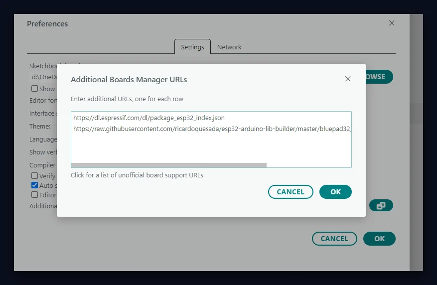
Then Tools → Board → Boards Manager, search Bluepad32, install Bluepad32 ESP32 (4.1.0 is the version this post was built with). It takes a few minutes.
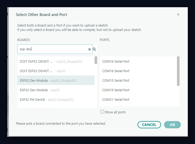
2. Board and port. Tools → Board → Bluepad32 ESP32 → ESP32 Dev Module. Or use the board selector at the top of the window and pick the entry marked esp32_bluepad32, not the plain esp32 one with the same name. Leave the partition scheme (how the ESP32’s flash memory is divided between program and data) on its default. Many Bluepad32 guides recommend “Huge APP”; this sketch does not need it. It compiles to about 758 kB, 57 % of the default 1.25 MB app partition. If you add a lot of your own code later and the upload fails with “sketch too big”, switch to Huge APP (3MB No OTA) then. That scheme gives the program 3 MB and reserves no space for OTA (over-the-air) updates over WiFi, which this firmware does not use. It uses no file system either, so nothing is lost.
3. Library. Adafruit PWM Servo Driver from the Library Manager. You have it from Part 1. Nothing else; Bluepad32 comes with the board package.
4. Open the sketch. firmware/OmArmOne_Gamepad/OmArmOne_Gamepad.ino from the repository. The IDE treats the folder as one program: open the .ino, the headers appear as tabs, one Upload builds all of it.
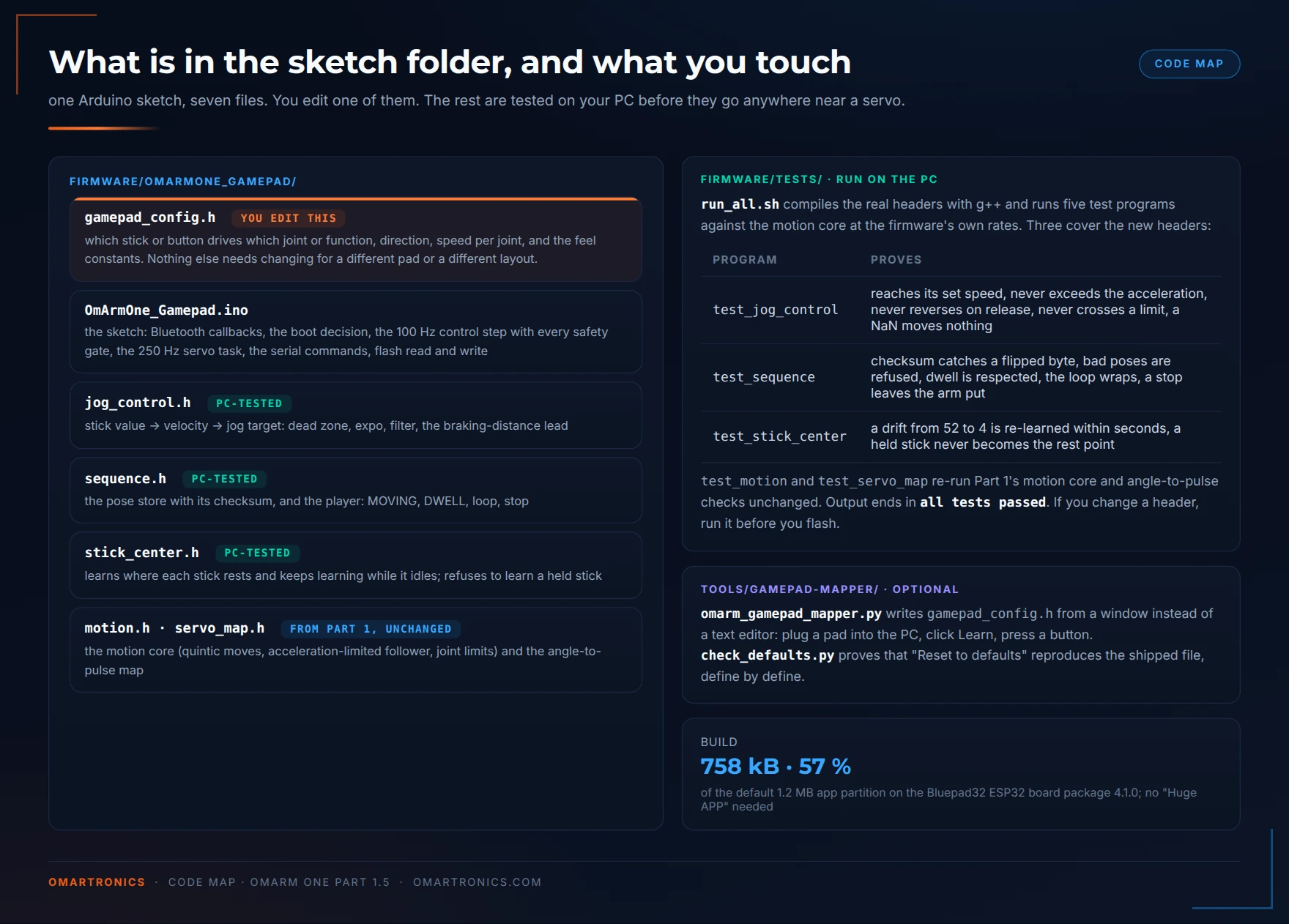
gamepad_config.h. The headers that contain the control logic are compiled and tested on your PC by the test script run_all.sh (section 7) before they run on the ESP32.5. Check the channel line. Same rule as Part 1: SERVO_CHANNELS[] = {0, 3, 4, 7, 8, 11} must match your wiring to the PCA9685. If it does in the web-app firmware, it does here.
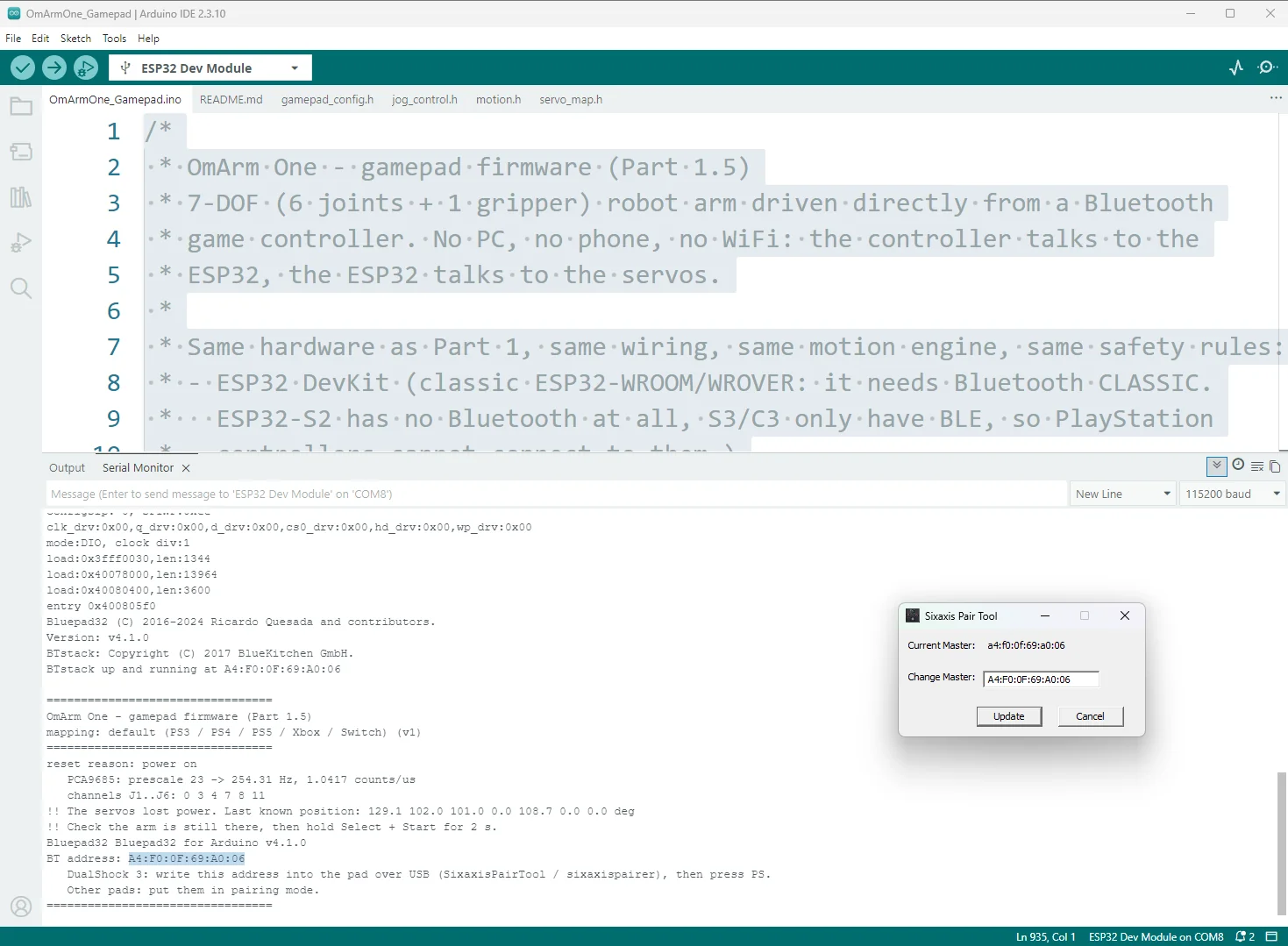
6. Switch the servo power off, close any open serial monitor, upload, then open the serial monitor at 115200 baud. An open serial monitor is the usual reason for “Failed to connect to ESP32: No serial data received”. If it still happens, hold the BOOT button on the board while the IDE says Connecting. You will see this:
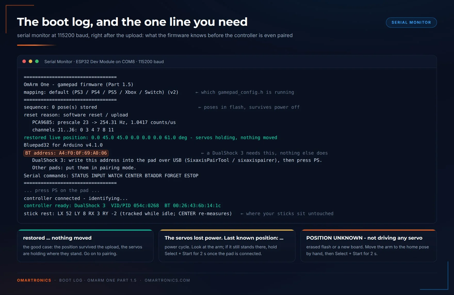
restored ... nothing moved is the good case. BT address is the number a DualShock 3 needs in the next section, and only a DualShock 3. Serial commands lists what you can type into the monitor.Check three lines. mapping: default ... (v2) names the gamepad_config.h that is running, so you know whether an edit reached the board. restored live position ... nothing moved means the position survived the upload and the servos were commanded to where they already stand. If you see The servos lost power instead, the firmware does not move the arm until you confirm the position with the controller (section 6).
4. Pairing, step by step
DualShock 3
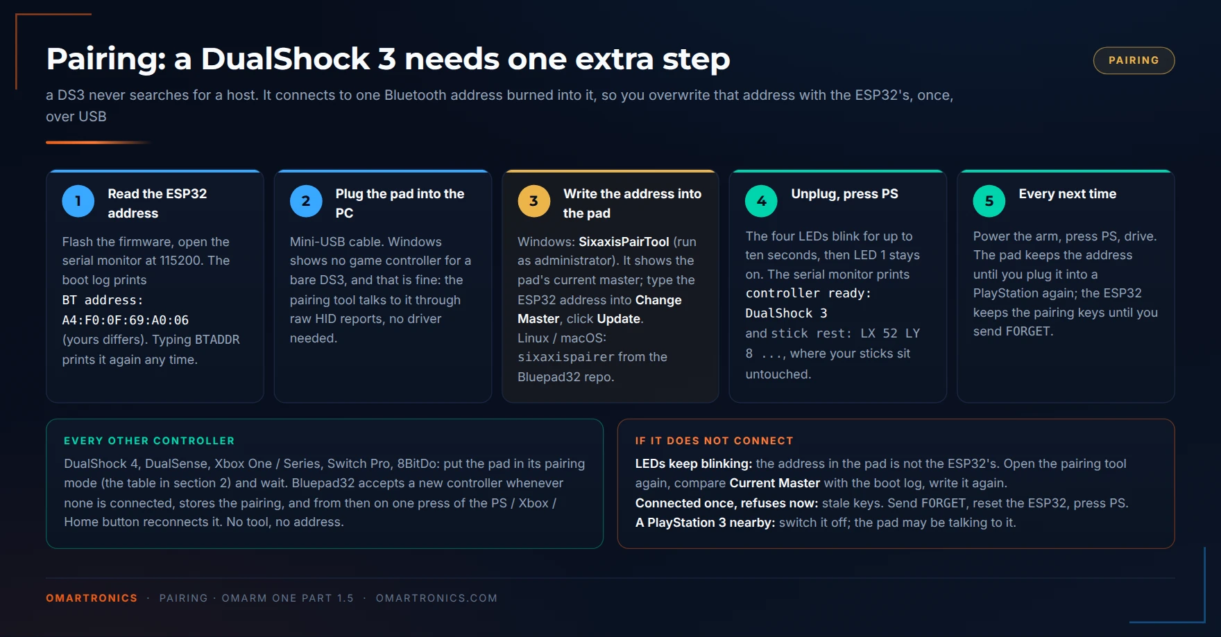
A DualShock 3 does not search for a host. It stores one host address, that of the last PlayStation it was connected to, and connects only to that address. To make it connect to the arm, you overwrite that address with the ESP32’s, once, over USB.
- Read the ESP32’s address from the boot log (
BT address: ...), or typeBTADDRinto the serial monitor and it prints the line again. - Plug the DualShock 3 into your PC with a mini-USB cable. Windows will not show a game controller for it. That is normal: there is no driver for a bare DualShock 3, and the pairing tool does not need one.
- Write the address into the controller. Windows: SixaxisPairTool. Run it as administrator. It shows the controller’s current master address (the stored host address); type the ESP32 address into the Change Master field and click Update. The tool’s author no longer distributes it, so you will find it on download mirrors. Check the installer with VirusTotal (a free online virus scanner) before running it; 0.3.1 is the last version. It communicates with the controller through raw HID reports: data packets that go to the device directly, without a driver. That is why Windows does not have to recognise the controller at all. Linux / macOS: the Bluepad32 repository has
tools/sixaxispairer. Build it (make sixaxispairer, needslibhidapi-dev) and runsudo ./sixaxispairer A4:F0:0F:69:A0:06with your own address. - Unplug the controller. Press the PS button. The four LEDs blink for up to ten seconds, then the serial monitor prints
controller connected - identifying...and, a moment later,controller ready: DualShock 3. Next comesstick rest: LX 52 LY 8 ..., the firmware’s measurement of where your sticks sit when nobody touches them. LED 1 stays on.
My own first pairing failed in the firmware, not in the controller. The DualShock 3 connected, but an early version asked for the controller type before Bluepad32 knew it and rejected the controller. The released firmware checks the type a moment later, in the control step.
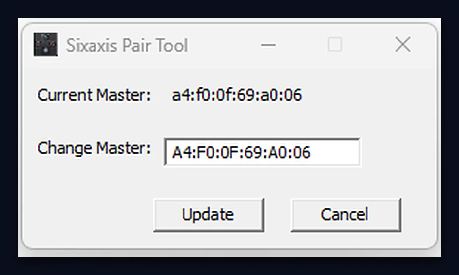
From then on the controller reconnects on a PS press every time the arm is powered. If you ever want it back on a PlayStation, plug it into the console with the cable once; the console rewrites the address.
Every other controller
Put the controller in pairing mode (table in section 1), and wait. Bluepad32 accepts new controllers whenever none is connected. Pairing is complete when the LEDs stop blinking and the serial monitor prints the model name. The pairing is stored on the ESP32, so next time you only press the PS, Xbox or Home button.
If a controller refuses to pair after it once worked, type FORGET into the serial monitor. That clears the stored keys on the ESP32 side, and you pair again from scratch.
5. The controls
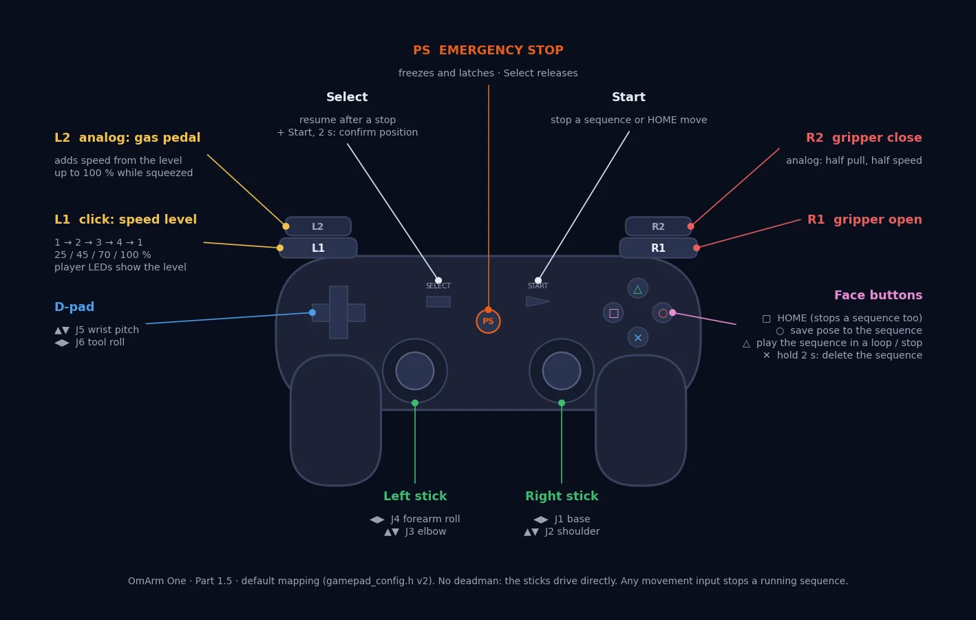
There is no button to hold before the arm moves. Push a stick and the joint turns; let go and it brakes to a stop. Section 9 explains what keeps this safe.
| Input | Function |
|---|---|
| Right stick left/right | J1 base, up to 70 deg/s |
| Right stick forward/back | J2 shoulder, up to 50 deg/s |
| Left stick forward/back | J3 elbow, up to 60 deg/s |
| Left stick left/right | J4 forearm roll, up to 60 deg/s |
| D-pad up/down | J5 wrist pitch, up to 60 deg/s |
| D-pad left/right | J6 tool roll, up to 90 deg/s |
| R1 / R2 | gripper open / close (R2 is analog: half pull is half speed) |
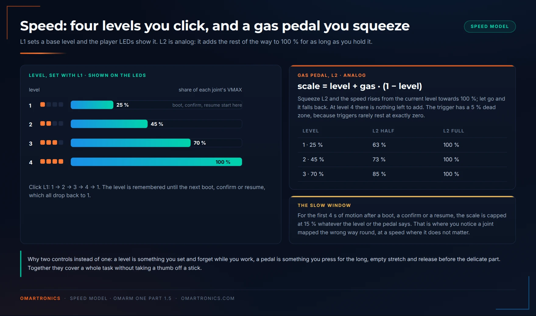
| L1 (click) | speed level 1 → 2 → 3 → 4 → 1: 25, 45, 70, 100 % of each joint’s maximum. The player LEDs show the level. Every boot, confirm and resume starts at level 1. |
| L2 (analog) | gas pedal: press it and the speed rises from the current level towards 100 %, release and it drops back |
| Square | HOME: every joint moves together to the home pose from Part 1 (angles in degrees: J1 0, J2 45, J3 45, J4 0, J5 0, J6 0, gripper 61). Also stops a running sequence first. |
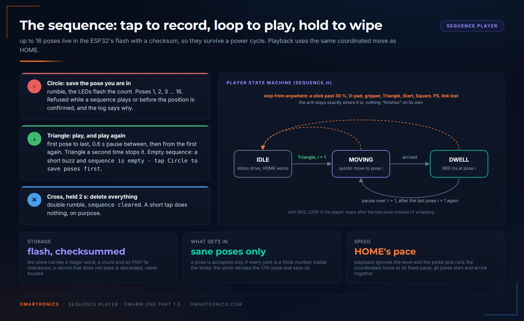
| Circle | save the current pose as the next step of the sequence (rumble, the LEDs blink the count). Up to 16 poses, stored in flash memory. |
| Triangle | play the sequence in a loop: first pose to last, 0.6 s pause between, then again from the first. Triangle again stops it. |
| Cross, hold 2 s | delete the whole sequence (double rumble). A short tap does nothing, on purpose. |
| Start | stop a running sequence or HOME move where it is |
| PS | EMERGENCY STOP. Freezes every joint where it is and latches. The servos keep holding; cutting their signal would let the arm drop. |
| Select | resume after a stop. Speed back to level 1, the next four seconds of motion are slow again. |
| Select + Start, hold 2 s | confirm the position after a power cycle, section 6 |
The per-joint speeds are not arbitrary. The shoulder carries the whole arm and gets the lowest limit; the tool roll carries only a gripper and gets the highest. Each number is MAP_Jx_VMAX in gamepad_config.h, and section 8 shows how to change them.
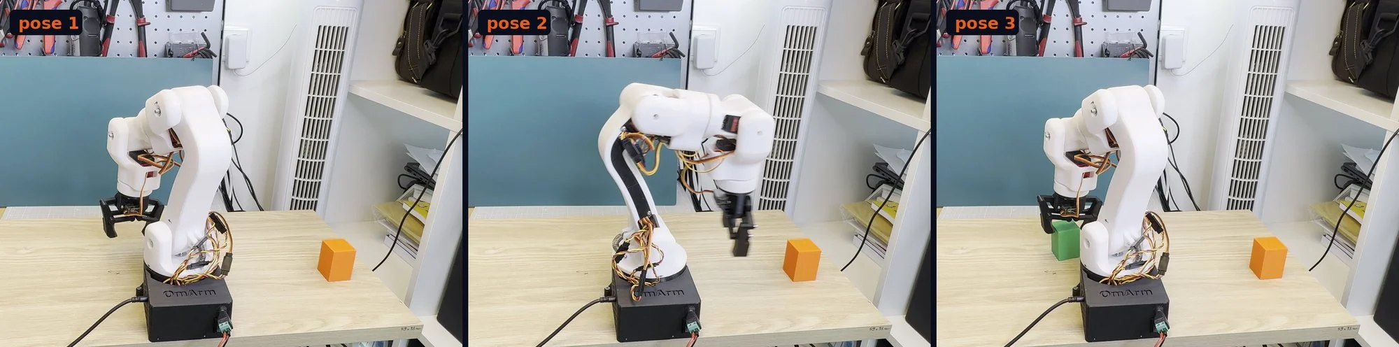
The sequence. Part 1’s web app could record poses too, but they lived in the browser and were gone after a reload. This one is written to the ESP32’s flash memory with a checksum (a number calculated from the data that shows whether the data was damaged). Switch the arm off and on again, and the sequence is still there (sequence: 3 pose(s) stored in the boot log). Drive to a pose, tap Circle. Drive to the next, tap Circle. Triangle plays them in a loop until you stop it, push a stick past 30 %, or press the D-pad, R1 or R2. Manual input always has priority, and the arm stops where it was interrupted.
While I filmed the video, the arm moved a cube around on its own for 20 minutes.
6. After a power cycle: the confirm gesture
Part 1 explained why an arm without position feedback must not move after its servos lost power. The stored position may be wrong, because gravity or a hand may have moved the arm while the servos were limp. The web app shows a warning and two confirm buttons. The controller has no screen, so the rule becomes a gesture: look at the arm, check it still stands where it was, then hold Select and Start together for two seconds. The controller rumbles, the servos energise at the stored position, and nothing moves.
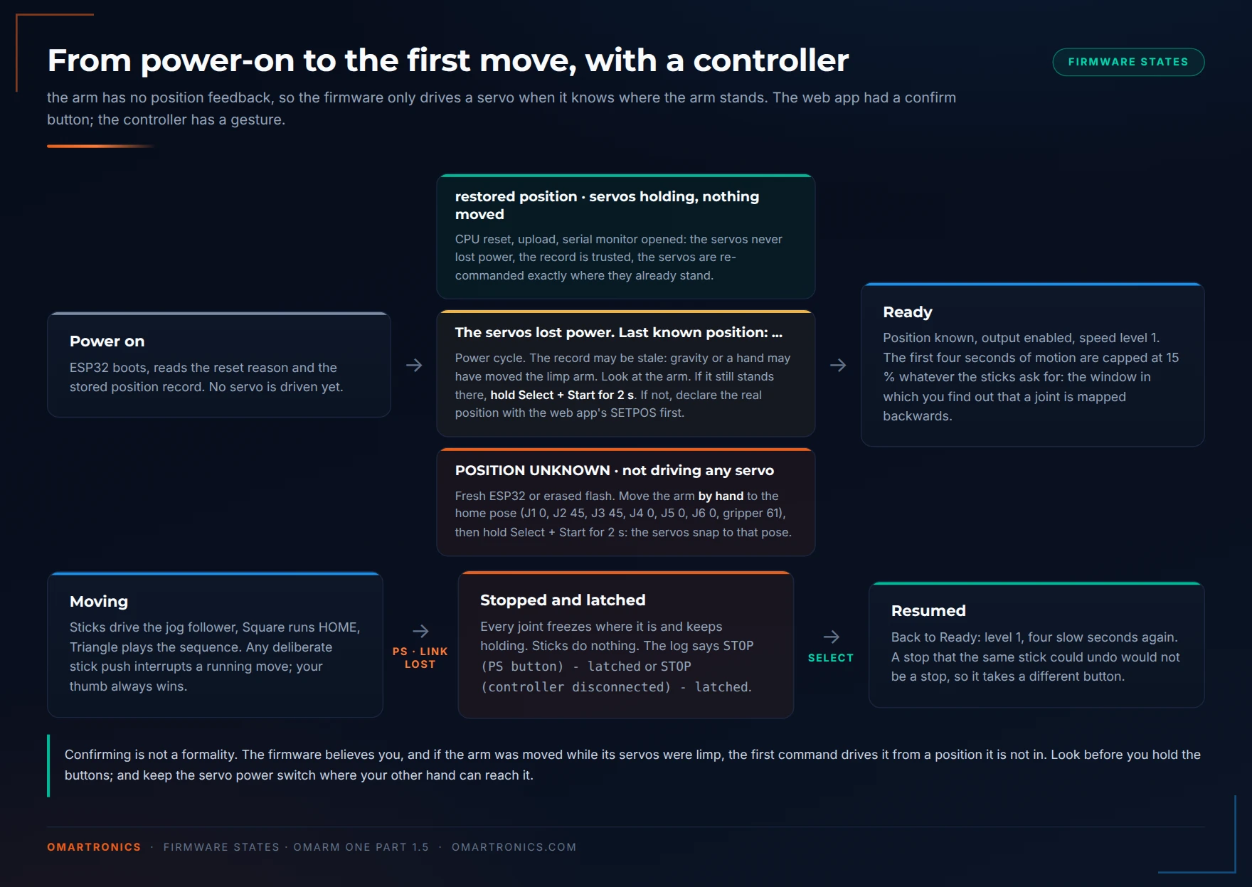
If the arm was moved while unpowered, do not confirm; flash the web-app firmware and declare the position with its banner buttons instead (Part 1, section 9). On a brand-new ESP32 with no stored position at all, the same gesture adopts the home pose, so move the arm to that pose by hand before you hold the buttons.
7. Why the motion is smoother than the sliders
Part 1 gave the arm two kinds of motion. The first is a coordinated point-to-point move with a quintic profile: velocity and acceleration are zero at both ends, and every joint arrives at the same time. The second is a jog follower for the sliders, which chases a moving target with limited acceleration and brakes early enough that it can never overshoot. The controller uses both. HOME and the sequence are coordinated moves. The sticks drive the jog follower, but differently from a slider.
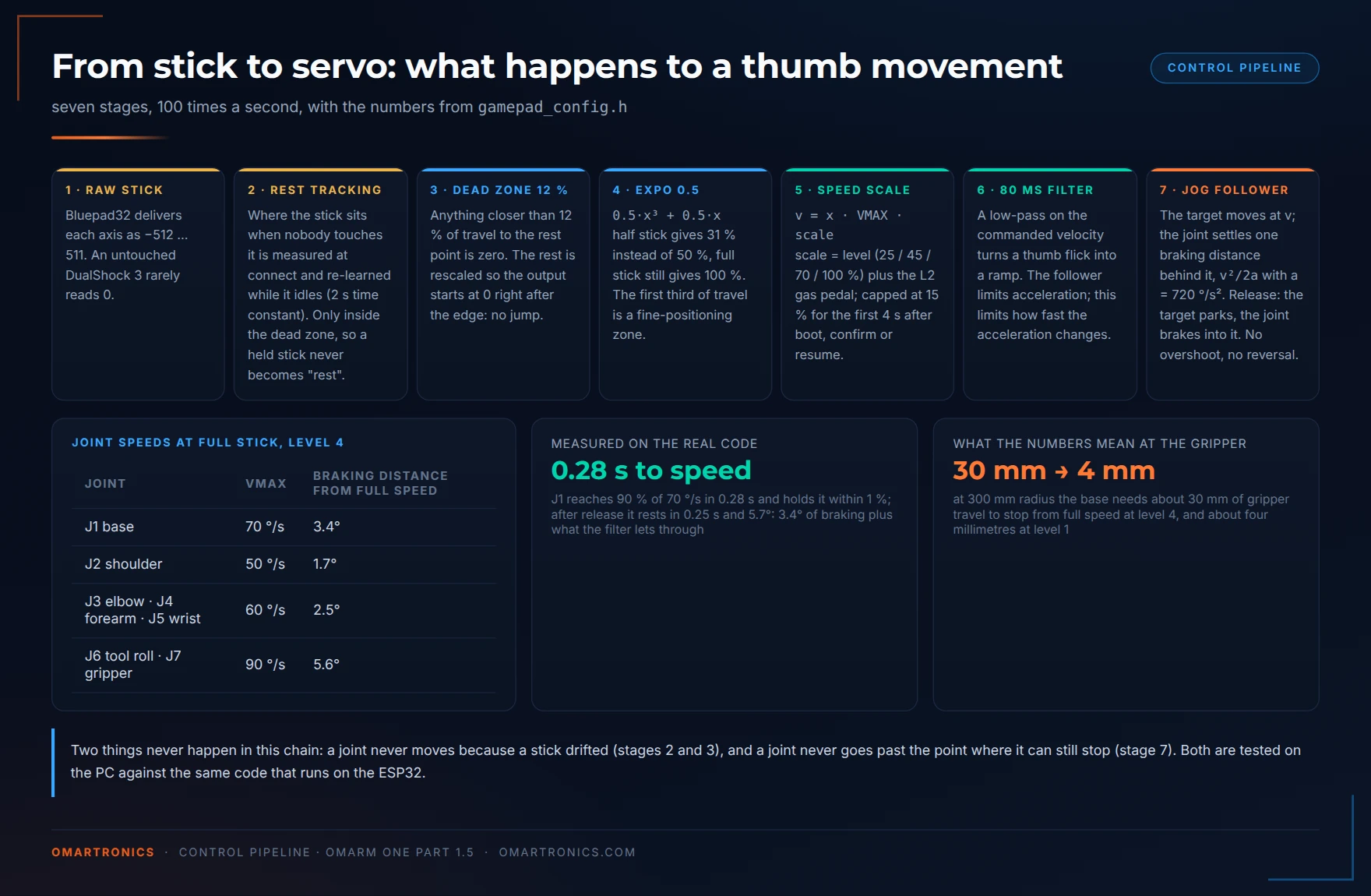
A slider sends a position. Drag it 20 degrees and the follower runs the joint 20 degrees and stops. A stick sends a fraction between −1 and +1, and the firmware turns that fraction into a velocity. Full stick means “turn this joint at its maximum speed”, half stick means half of it, centre means stop. The level and the gas pedal from section 5 scale it, and three more stages follow.
Rest position and dead zone. A stick that is not touched rarely reads exactly zero, and a worn DualShock 3 is worse: mine rests 10 % off centre, and not at the same spot twice. So the firmware measures where each stick rests when the controller connects, and keeps measuring while the stick is idle. It does this slowly enough that a stick you hold at a small deliberate deflection is never mistaken for “rest”. A ±12 % dead zone follows, rescaled so the first millimetre past it starts at zero speed rather than jumping to 12 %. Together, rest tracking and the dead zone keep an untouched controller from moving a joint and a drifting stick from blocking HOME or the sequence. A stick worn past 12 % can still cause creep; see Troubleshooting.
Expo curve. Thumbs are precise near the centre and coarse at the edge. The command is blended between linear and cubic: 0.5·x³ + 0.5·x. At half stick the joint runs at 31 % of its maximum instead of 50 %; at full stick it still reaches 100 %. The first third of travel becomes a fine-positioning zone.
Velocity filter. A thumb can flick a stick from centre to full in a few milliseconds. The commanded velocity passes through an 80 ms low-pass filter, so a flick becomes a ramp. The follower already limits acceleration; the filter also limits how fast the acceleration changes (the jerk), so the joint starts and stops smoothly.
The follower from Part 1 runs toward its target at the fastest speed from which it can still stop inside the remaining distance: v_stop = √(2·a·d). To make a joint cruise at velocity v, the target moves at v, and the follower settles exactly one stopping distance behind it: d = v²/(2a). With the shipped acceleration of 720 deg/s² and the base at 70 deg/s that is 3.4 degrees. Release the stick, and the target is parked at that stopping distance in front of the joint. The follower decelerates at 720 deg/s² and comes to rest right there. It cannot overshoot, because the target never lies beyond the stopping point, and it cannot bounce, because the follower never reverses direction.
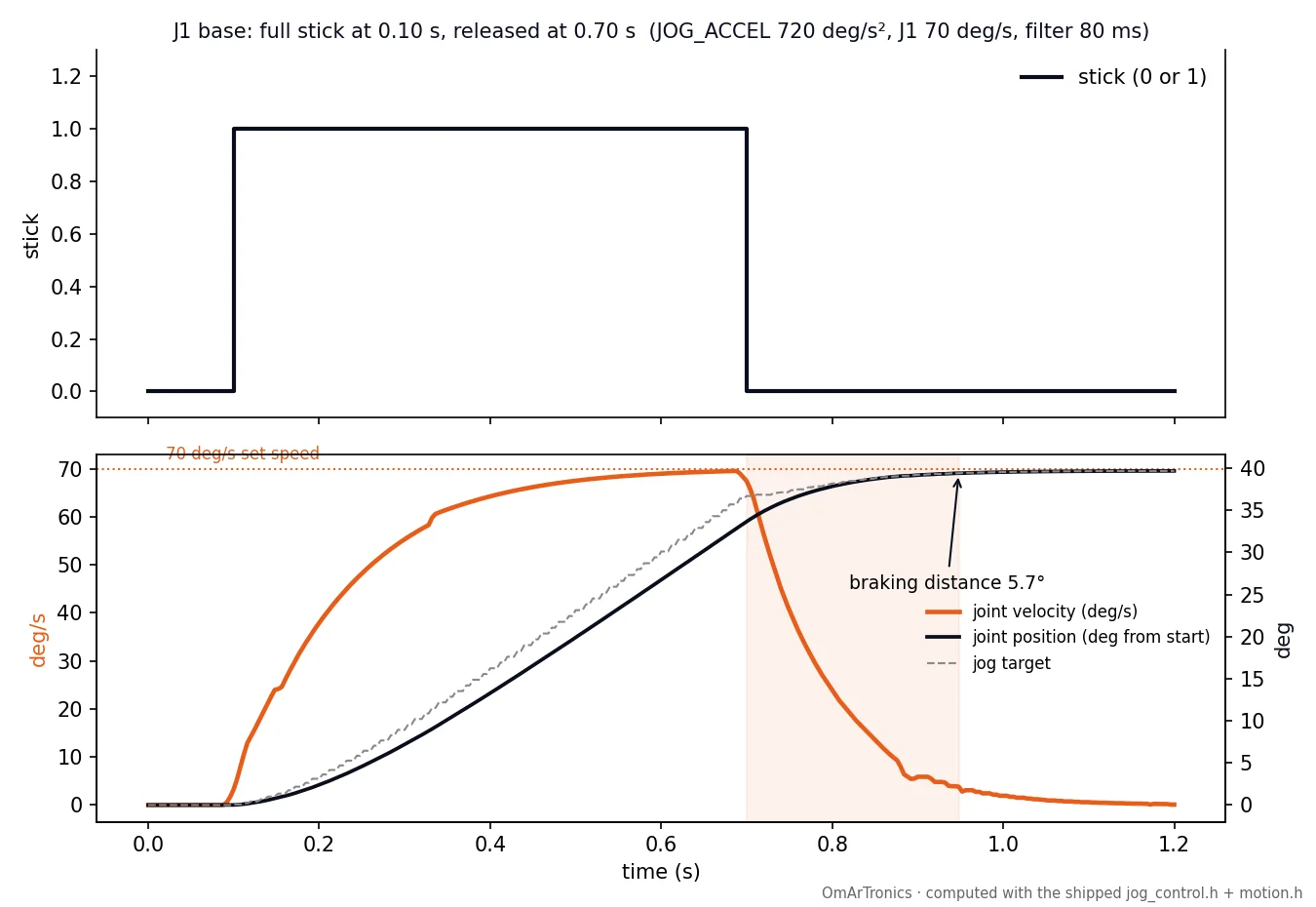
jog_control.h and motion.h that run on the ESP32, at the firmware’s own 100 Hz control and 250 Hz servo rates. The joint reaches 90 % of its 70 deg/s in 0.28 s and holds it within 1 %. After release it comes to rest in 0.25 s and 5.7 degrees: 3.4 of braking plus what the 80 ms filter lets through. Nothing in the curve goes backwards.That braking distance matters when you drive near a wall or a person. At full speed the base needs about six degrees to come to rest, which at 300 mm radius is 30 mm of gripper travel after you let go. At speed level 1 the base runs at 17.5 deg/s and that shrinks to a few millimetres.
Stick input and coordinated moves do not conflict. While HOME or the sequence is running and no stick is touched, the follower does not change the move. Push a stick clearly (past 30 % of travel, which drift never reaches) and the move is cancelled where it is.
All of this is tested on the PC before it runs on the ESP32. The script run_all.sh in the gamepad test folder compiles the real headers with g++ (a C++ compiler for the PC) and runs them against the motion core at the real rates. In the GitHub repository that folder is firmware/tests-gamepad/; in the complete package it is firmware/tests/ inside the Part 1.5 folder. The five programs and what each proves are in the code map in section 3. The run ends in all tests passed; if you change a header, run it before you flash.
8. Changing the mapping: by hand or with the mapper tool
Everything about the controls lives in gamepad_config.h. It is short, and it is meant to be edited.
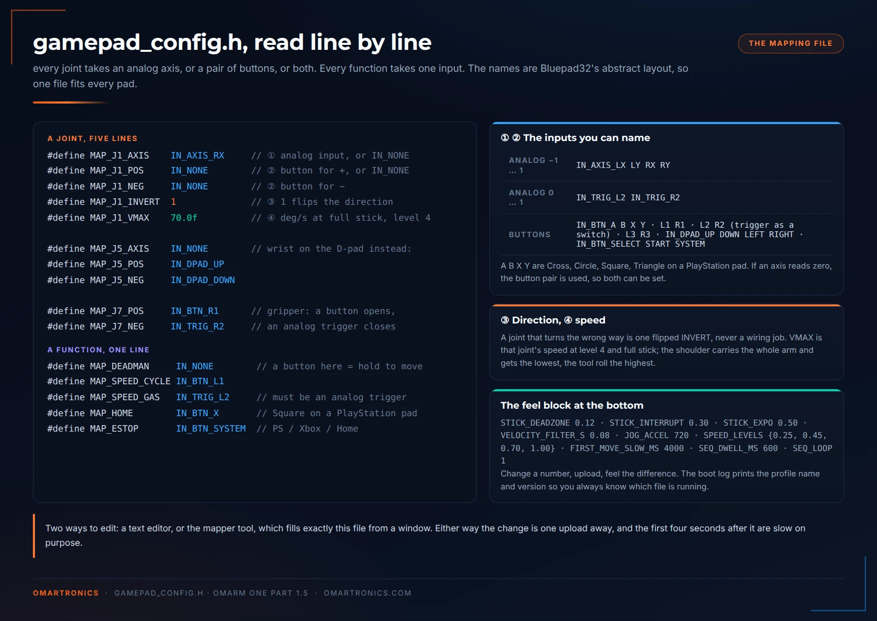
Typical edits: to put the shoulder on the left stick and the elbow on the right, swap two lines. To add a deadman button (nothing moves unless it is held), set MAP_DEADMAN to a button. To play the sequence once instead of looping, set SEQ_LOOP 0; SEQ_DWELL_MS sets the pause between poses. Each change needs one upload. The boot log prints the mapping name and version (mapping: default ... (v2)) so you know the change arrived, and the first four seconds after it are slow on purpose.
The mapper tool does the same with a controller in your hand instead of a text editor. It is a small Python program in tools/gamepad-mapper/. It needs two libraries: pygame (reads game controllers on the PC) and pyserial (serial communication with the ESP32 over USB):
pip install pygame pyserial
python omarm_gamepad_mapper.py
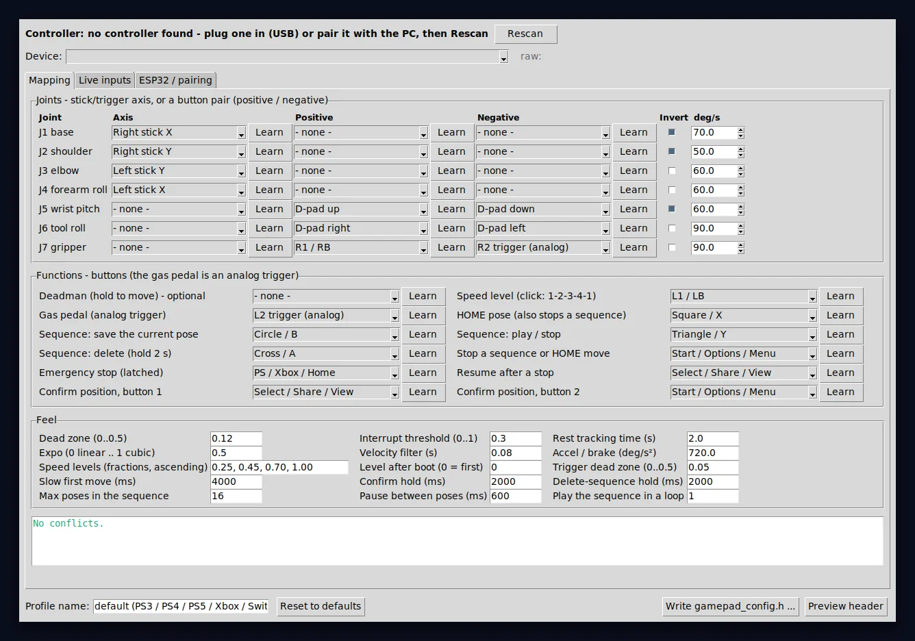
gamepad_config.h straight into the sketch folder. The screenshot was taken on Linux.It finds the controller and shows every stick and button live, so you know a controller works before you flash the ESP32. It learns bindings by touch. On its ESP32 tab it reads the BT address line from the arm over USB, with a button that copies it for the pairing tool. The “Reset to defaults” button restores the mapping this post describes. The script check_defaults.py in the same folder verifies this for every #define line in the header.
The tool works on any controller the PC sees as a game controller. SDL (Simple DirectMedia Layer, the library pygame uses to read controllers) maps common controllers on the PC to the same layout that Bluepad32 uses on the ESP32. You can learn a binding on an Xbox controller at the desk, flash the ESP32 and then drive with a DualSense. One exception: Windows has no driver for a bare DualShock 3, so the tool cannot see that one controller. Pick its inputs from the lists instead, or skip the tool altogether: the shipped header already is the DualShock 3 layout, and pairing does not need the tool either.
9. The safety layer
Part 1’s rules all still apply. No motion before the position is known. A stored position that survived a reset is trusted, and one that did not is confirmed by a human. The first move after a boot is slow. A failure on the I2C bus (the two-wire link from the ESP32 to the PCA9685) disables the servo output. The gamepad firmware adds four rules and adapts two Part 1 rules (slow start, confirmation) to a controller without a screen. Each one answers a specific way a wireless link, a worn stick or a screenless device can go wrong.
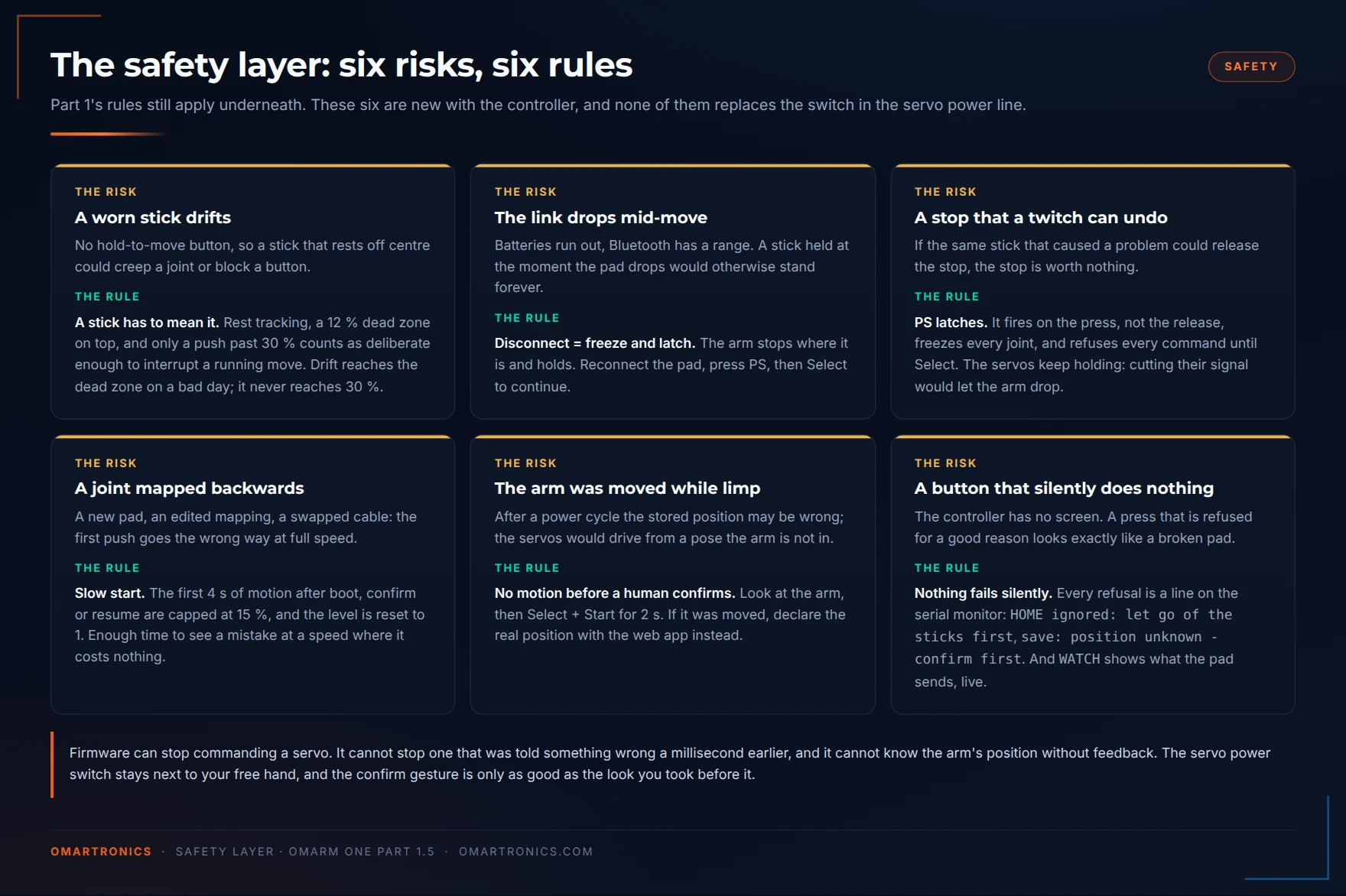
Only deliberate stick input counts. There is no hold-to-move button, so the firmware must separate a deliberate push from an accidental wobble. Rest tracking and a 12 % dead zone filter out the wobble. Only a deflection past 30 % is deliberate enough to interrupt a running move. If you prefer a deadman button, one line in gamepad_config.h gives you one.
Disconnect. Batteries run out and Bluetooth has a range; a DualShock 3 blinks its LEDs when its battery runs low. If the connection drops while a stick is held, the last command would otherwise stand forever. On a disconnect the arm freezes where it is and latches; reconnect the controller, press PS, then Select to continue.
Latched stop. The PS button fires on the press, not on the release, freezes the arm and refuses every command until Select is pressed. Sticks cannot release it, so the input that caused the problem cannot restart the arm.
Slow start. The first four seconds of motion after a boot, a resume or a confirm are capped at 15 % speed, whatever the level or the gas pedal says. The level itself is reset to 1. That is the window in which you find out that a joint is mapped the wrong way round.
No motion before a human confirms. Section 6 describes the confirm gesture. The firmware accepts the confirmation without checking; look before you hold the buttons.
Nothing fails silently. When the firmware refuses a button press, it prints the reason on the serial monitor. Examples: HOME ignored: let go of the sticks first, sequence is empty - tap Circle to save poses first, save: position unknown - confirm first. And WATCH streams every stick and button five times a second, so when something feels wrong you can see what the controller sends.
Two of these rules come from my own testing. My first version had L1 as a deadman button: hold it to move. After one evening it felt like a handbrake, so I removed it; rest tracking, the dead zone and the 30 % threshold do that job now. In an early version, the off-centre stick of my worn DualShock 3 also blocked HOME, and the firmware gave no reason. Since then every refusal prints its reason on the serial monitor.
As in Part 1: none of this replaces a switch in the servo power line. The firmware can stop commanding a servo; it cannot stop one that was told something wrong a millisecond earlier. Keep the switch where your other hand can reach it.
10. First drive: a bench checklist
Servo power off, arm in its home pose, nothing in the gripper. Then in this order:
- Boot and read the log.
restored ... nothing movedor a confirm prompt. Nothing else is acceptable;POSITION UNKNOWNon an arm that was set up in Part 1 means the flash memory was erased, so declare the position with the web-app firmware first. - Pair.
controller ready: DualShock 3in the log, thenstick rest: .... LED 1 on: speed level 1. - Confirm if asked. Look at the arm, then Select + Start for two seconds. The log says
position adopted. - Servo power on. The arm must not twitch. If it does, the stored position and the real arm disagree: power off, fix it with the web app.
- Right stick a little to the right. The base turns slowly to the right, and the log says
moving. If it turns left, flipMAP_J1_INVERT. Check each joint the same way. The first four seconds are slow whatever you do; for another slow pass, press PS and then Select. - Let go mid-move. The joint brakes to a stop; a moment later the log says
idle. - Press L2 while turning. The base speeds up with the trigger and slows down when you release it. Click L1 twice: three LEDs, and the same stick deflection is now much faster.
- PS button mid-move. Everything freezes, the log says
STOP (PS button) - latched. Sticks do nothing. Select releases it, and the LEDs are back to one. - Switch the controller off mid-move (hold PS for ten seconds on a DualShock 3). The arm freezes and latches. Switch the controller on, press PS, then Select.
- Square. The arm returns to the home pose, all joints together, in about two seconds.
- Drive a pose, tap Circle (rumble, LEDs blink once). Drive somewhere else, tap Circle again (two blinks). Triangle. The arm plays both poses and starts over. Nudge a stick: it stops where it is. Triangle again: it plays again. Hold Cross for two seconds: double rumble,
sequence cleared.
If all eleven checks pass, the setup is complete.
11. Troubleshooting
| Symptom | Cause | Fix |
|---|---|---|
| Upload fails: “No serial data received” | the serial monitor holds the port, or the auto-reset (the automatic switch of the ESP32 into upload mode) did not work | close the serial monitor; if it persists, hold BOOT on the board while the IDE says Connecting |
| Upload fails: “sketch too big” | you added code and outgrew the 1.25 MB app partition | Tools → Partition Scheme → Huge APP (3MB No OTA); this firmware uses no file system, nothing is lost |
Bluepad32.h: No such file | sketch compiled for the plain ESP32 board | Tools → Board → Bluepad32 ESP32 → ESP32 Dev Module (the entry marked esp32_bluepad32) |
| SixaxisPairTool says “no device found” | the controller is not in USB data mode, or the cable is charge-only | use a cable with data lines (many cheap mini-USB cables only charge). Plug the controller in before starting the tool, run the tool as administrator, and press PS once to wake the controller |
| DualShock 3 blinks, never connects | wrong or unwritten master address, or a clone | re-read BTADDR, write it again; check the back label for a Sony model number |
| DualShock 3 connects to something else | a PS3 nearby is on | switch the console off |
Controller connected but nothing moves, no moving in the log | position not confirmed, or stop latched | type STATUS: known=0 means confirm (Select + Start 2 s), estop=1 means Select. WATCH shows whether the sticks arrive at all |
| One joint moves the wrong way | direction of that axis | flip MAP_Jx_INVERT |
| Sticks move the wrong joints | swapped axes, or the controller reports a different layout | run the mapper tool’s Live inputs tab and rebind |
| A joint creeps with the stick untouched | rest tracking not settled yet, or a stick worn past 12 % | let go of the sticks for three seconds, or type CENTER; if it persists raise STICK_DEADZONE to 0.15 |
| Square or Triangle does nothing | a stick is not centred | the log says HOME ignored: let go of the sticks first with the values; WATCH shows them live |
| Motion feels laggy | filter too long | lower VELOCITY_FILTER_S to 0.05; below 0.03 the ramp is gone |
| Motion feels twitchy | acceleration too high | lower JOG_ACCEL to 480 |
late servo ticks in the log | Bluetooth stack starving the servo task | should not happen on the original ESP32; report it with the log |
| Controller worked, now refuses to pair | stale keys on the ESP32 | type FORGET, pair again |
12. FAQ
Can I keep the web app and the controller at the same time? Not in this firmware. The two radios share one antenna and the servo timing is the thing I refuse to compromise. Part 3’s serial firmware will take both a controller (through ROS 2) and the twin.
Can two controllers connect? Bluepad32 allows up to four; the firmware accepts the first and ignores the rest.
Can I use the sticks for the gripper and the triggers for a joint? Yes. Any analog input can drive any joint. Set MAP_J7_AXIS to a stick axis (in gamepad_config.h the gripper is J7). For the joint that moves to the triggers, set the two triggers as its POS and NEG inputs (one trigger for each direction).
Why does level 4 with the gas pedal not go any faster? Level 4 already is each joint’s VMAX, and those are set where the servos still track the profile cleanly under load. You can raise them in gamepad_config.h; the DS3240 reaches about 300 deg/s at 5 V (327 deg/s at 6 V) without load, but not with the arm’s inertia on it.
Will this work on OmArm Zero? The motion core is the same and the wiring is close. Zero uses the same six PCA9685 channels (0, 3, 4, 7, 8, 11), but as five joints plus the gripper on channel 11 instead of six joints and a gripper on an ESP32 pin. Change NUM_SERVOS, the channel table, the gripper output and the home pose and it should; I have not tested it.
13. What comes next
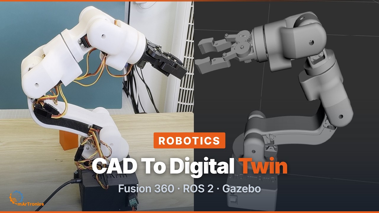
Part 2 is live. The arm now has a digital twin: the CAD model exported to URDF (Unified Robot Description Format, a text file that describes the arm’s links and joints). The model was audited and corrected, and it runs in RViz (the ROS 2 visualisation tool) and in Gazebo Harmonic (a physics simulator) on ROS 2 Jazzy.
The firmware still does not know where the gripper is in space. Six joint angles are not a gripper position; the maths that turns one into the other (forward kinematics) runs on the PC, in the digital twin.
Part 3 uses the serial firmware from section 2 and adds the ROS 2 driver and MoveIt 2 planning, so the controller you paired drives the twin on screen and the twin drives the arm. Part 4 adds a camera, and in Part 5 you tell the arm what to pick up.
If you build the controller setup, I would like to see your mapping. If you find a controller that does not pair, tell me the model number; the table in section 1 grows with every report.
Resources
- Gamepad firmware, mapper tool and tests (MIT): github.com/OmArTronics/OmArm-One →
firmware/OmArmOne_Gamepad/,firmware/tests-gamepad/,tools/gamepad-mapper/. - Bluepad32, the Bluetooth controller stack: bluepad32.readthedocs.io.
- The arm itself, STLs and build guide: OmArm One complete package in the shop and Part 1 build guide.