
OmArm One Series
Part 1: Build, statics and payload · Part 1.5: Drive it with a game controller · Part 2: The ROS 2 digital twin · Part 3: ros2_control, kinematics and MoveIt 2 (this post) · Part 4: Computer vision pick and place (coming soon) · Part 5: AI: grasping by name, by voice (coming soon)You need the digital twin from Part 2 and, for the second half, a finished OmArm One. Everything up to section 11 runs on a PC alone.
Video: the Part 3 walkthrough is coming to the OmArTronics YouTube channel; this paragraph is replaced by the player when it is live.
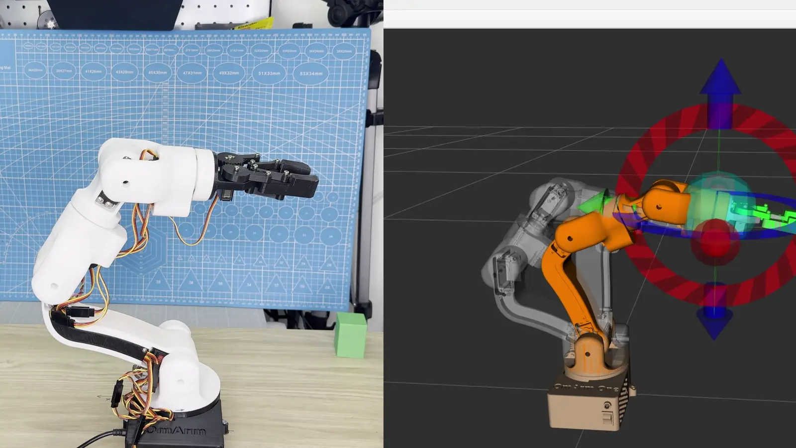
Part 2 ended with a model that looked right. The arm stood in RViz, it fell over in Gazebo when nothing held it, and the silhouette matched a photograph of the real machine. That is further than most CAD exports get, and it is still not a robot you can command.
Two things were missing, and they are what this part is about.
The first is that a model which looks right in a picture can still be wrong in every direction that matters. Photographs are forgiving: a joint that turns the wrong way looks identical to one that turns the right way, as long as you only ever look at one still frame. Move it, and the arm on screen goes left while the arm on the bench goes right. I found four of those in my own model, and I found them with a ruler and my eyes, not with software.
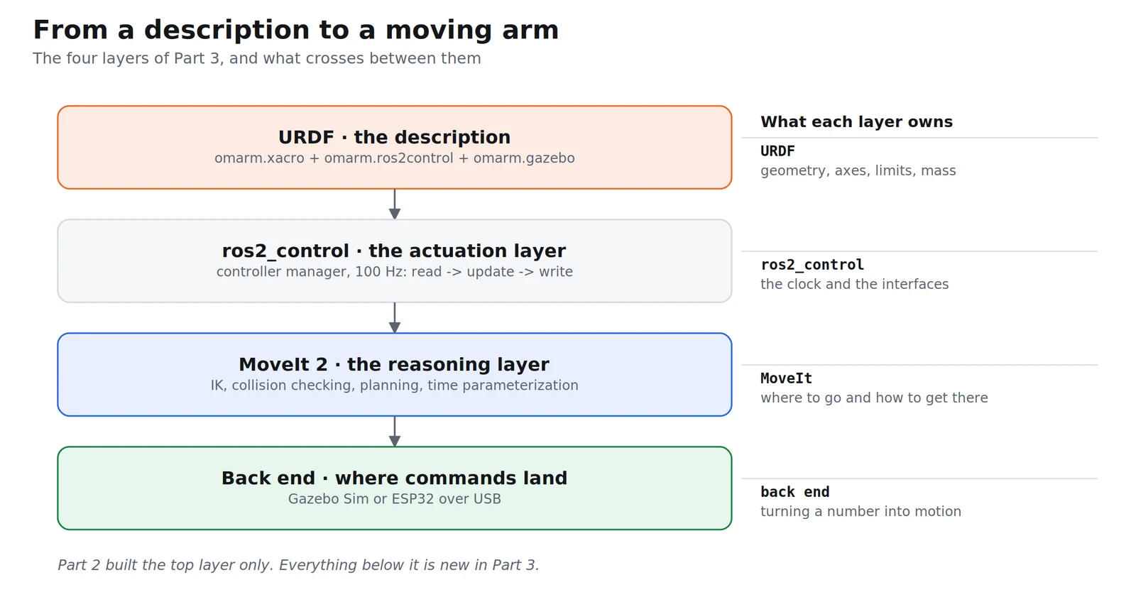
The second is that nothing in Part 2 could actually drive a joint. RViz draws whatever angles you feed it. Gazebo simulates physics on a model. Neither of them contains the piece that takes a command, converts it into something a motor understands, and reports back what the motor did. That piece is ros2_control, and once it is in place the same description runs a simulation and a real arm without changing a line.
And then the part everyone actually wants: giving the robot a point in space instead of six angles. Everything the OmArm One has done so far (sliders in Part 1, a thumbstick in Part 1.5, a joint trajectory message in Part 2) was the same operation dressed differently. You say the angles, the arm goes there. That is forward kinematics, and it is the easy direction. The hard direction is the useful one: here is where the gripper should end up, work out the angles yourself.
This post derives that hard direction for the OmArm One properly — a Denavit–Hartenberg table straight out of the URDF, a closed-form solution with all eight branches, and a number for how wrong the closed form is compared to the exact geometry. Then it hands the problem to MoveIt, which does the same thing with a numerical solver, adds collision checking and timing, and drives the real arm through the same interface it uses for the simulation.
At a glance
What you’ll build: a calibrated URDF that matches the physical arm joint for joint, a complete ros2_control setup with three controllers, a MoveIt 2 configuration package, and a hardware driver that runs a MoveIt-planned trajectory on an ESP32-driven arm over a single USB cable.
What you’ll learn: every way a CAD export can disagree with the machine it describes, and how to find each one. What a controller actually is in ROS 2 and who orchestrates them. How to derive DH parameters from a URDF and check them. The closed-form inverse kinematics of a 6R arm with a spherical wrist, with all eight solutions. Why trajectory planning is not the same as inverse kinematics, and what time parameterization adds. Every screen of the MoveIt Setup Assistant. How a position command becomes a servo pulse, and what has to be true for the arm not to jump when you start the stack.
Time required: an evening for the URDF audit if your arm is built. Half an hour for the MoveIt package. The hardware section depends on whether your firmware is already flashed.
Total cost: 0 €. Everything in this part is software, plus the arm from Part 1.
Software: Ubuntu 24.04 · ROS 2 Jazzy · MoveIt 2 · Gazebo Harmonic · ros2_control · Arduino IDE for the firmware.
Files: the complete workspace (omarm_description, omarm_hardware, omarm_moveit_config, omarm_simulation, the ESP32 firmware and the command-line tools) ships in the Part 3 download.
Table of contents
- What Part 2 left unfinished
- Every way a CAD export lies about your robot
- The audit: what actually changed in the URDF
- ros2_control: the layer that makes joints move
- The three controllers, and who orchestrates them
- Forward kinematics: what we have been doing all along
- Denavit–Hartenberg, derived from the URDF
- Inverse kinematics in closed form
- Why MoveIt solves it numerically anyway
- After IK: trajectories and time parameterization
- What MoveIt actually is
- Building the configuration package with the Setup Assistant
- MoveIt in RViz and Gazebo
- Talking to the real hardware
- Driving the real arm from MoveIt
- Troubleshooting
- FAQ
- What comes next
1. What Part 2 left unfinished
The package from Part 2 does three things. robot_state_publisher reads the URDF and turns a set of joint angles into a tree of coordinate frames. A slider window publishes those angles. RViz draws the result. Add Gazebo and the same description gets mass, gravity and contact.
What none of that does is move anything on purpose. The slider window is a publisher of numbers; Gazebo applies physics to a model; RViz is a viewer. When you spawned the arm in Gazebo at the end of Part 2 it sagged, because nothing was holding the joints. That sag is the honest picture of where Part 2 stopped: a complete description, zero actuation.
The gap has a name in ROS 2. ros2_control is the framework that sits between “a controller wants this joint at 0.8 rad” and “something physical made that happen”. It is the same framework whether the something physical is a Gazebo model or an ESP32 with seven servos on it, and that is the whole point. Section 4 gets into it properly.
But there is an order to this. Putting a control layer on top of a model that does not match the machine gives you a very reliable way to break the machine. So the audit comes first.
2. Every way a CAD export lies about your robot
The Fusion 360 URDF exporter writes a faithful description of the CAD assembly. Whether the CAD assembly is a faithful description of the thing on your bench is a separate question, and the answer is usually no. Here is the full list of what can disagree, in the order I would check them.
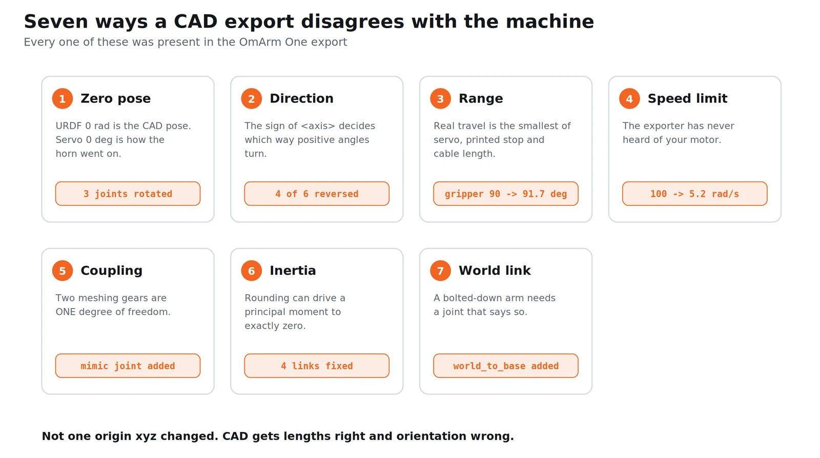
The zero pose. A URDF joint at 0 rad is whatever pose the assembly was in when you ran the exporter. A servo at 0° is whatever pose its horn was in when you bolted it on, and a splined horn can only be fitted in discrete steps. These agree only by luck. On the OmArm One four joints needed their zero rotated — the base by −90° about its own axis, then −77.70°, +77.92° and +90° on three more. The exact values are in the table in section 3.
The direction of rotation. This is the one that looks like nothing and breaks everything. A URDF joint has an <axis>, and the sign of that axis decides which way positive angles turn. A servo has its own idea, set by how it is mounted and which way the output shaft faces. Get it wrong and every command is mirrored: you ask for +30° and the joint goes to −30°. In a still photograph this is invisible. In motion it is immediate.
The range. The exporter writes whatever limits you set in CAD, or nothing. The real range is set by the servo’s own travel, by where the horn hits a printed stop, and by how far the cable loom will stretch. The number that belongs in the URDF is the smallest of those three, not the largest.
The velocity and effort limits. The exporter has no idea what motor you fitted. Part 2’s export carried velocity="100" on every joint. That is 100 rad/s, or 5730 °/s. The DS3240-180 is rated 0.20 s/60° at 5 V — 300 °/s with no load at all, and that is the optimistic end of the figure. A limit nineteen times faster than the motor is not a limit, it is a lie that planners will happily believe.
Coupled joints. The OmArm One’s gripper has two gears that mesh. Mechanically that is one degree of freedom. In the CAD export it is two independent revolute joints, and every planner that reads the file will think it can drive them apart.
Degenerate inertia. The exporter rounds. On small parts it rounds a principal moment of inertia to zero, which is physically impossible: it would mean mass with no extent about that axis. The ROS 2 documentation is explicit about the consequence: “When using realtime controllers, inertia elements of zero (or almost zero) can cause the robot model to collapse without warning, and all links will appear with their origins coinciding with the world origin.”
No fixed reference. A robot arm that is bolted to a table needs a joint that says so. Without it the base is free, and in Gazebo the whole arm is a rigid body lying in a gravity field.
No control description at all. The exporter does not write a <ros2_control> block. Section 4 explains why that means the model cannot be driven by anything.
The tools for finding most of these are not software. A ruler, a protractor, a printed angle template taped to the base, and the willingness to command one joint at a time and watch which way it goes. I moved each joint alone, compared the direction on screen with the direction on the bench, and wrote down the ones that disagreed. That took twenty minutes and found four.
3. The audit: what actually changed in the URDF
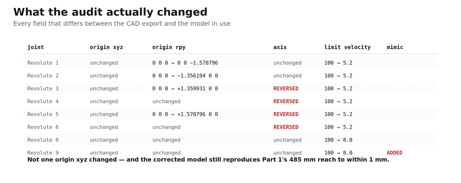
This is the complete diff between the file the exporter wrote and the file that MoveIt and the hardware driver use. I compared them mechanically: both normalised to LF line endings (the export uses CRLF, which otherwise reports every line as changed), then parsed as XML and compared attribute by attribute.
Joints
| Joint | Field | CAD export | Calibrated | What it means |
|---|---|---|---|---|
| Revolute 1 | origin rpy |
0 0 0 |
0 0 -1.570796 |
base rotated −90° about Z |
| Revolute 1 | limit velocity |
100 |
5.2 |
5.2 rad/s = 297.9 °/s |
| Revolute 2 | origin rpy |
0 0 0 |
-1.356194163 0 0 |
−77.70° about X |
| Revolute 2 | limit velocity |
100 |
5.2 |
|
| Revolute 3 | origin rpy |
0 0 0 |
1.359931089 0 0 |
+77.92° about X |
| Revolute 3 | axis |
1.0 0.0 -0.0 |
-1.0 0.0 -0.0 |
direction reversed |
| Revolute 3 | limit velocity |
100 |
5.2 |
|
| Revolute 4 | axis |
-0.0 0.984808 0.173648 |
0.0 -0.984808 -0.173648 |
direction reversed |
| Revolute 4 | limit velocity |
100 |
5.2 |
|
| Revolute 5 | origin rpy |
0 0 0 |
1.570796 0 0 |
+90° about X |
| Revolute 5 | axis |
1.0 0.0 -0.0 |
-1.0 0.0 0.0 |
direction reversed |
| Revolute 5 | limit velocity |
100 |
5.2 |
|
| Revolute 6 | axis |
-0.0 0.984808 0.173648 |
0.0 -0.984808 -0.173648 |
direction reversed |
| Revolute 6 | limit velocity |
100 |
5.2 |
|
| Revolute 8 | limit upper |
1.570796 |
1.6 |
90.00° → 91.67° |
| Revolute 8 | limit velocity |
100 |
8.0 |
8.0 rad/s = 458.4 °/s |
| Revolute 9 | limit upper |
1.570796 |
1.6 |
|
| Revolute 9 | limit velocity |
100 |
8.0 |
|
| Revolute 9 | mimic |
absent | joint="Revolute 8" multiplier="1" offset="0" |
new — the coupled gear |
world_to_base |
— | does not exist | fixed, world → base_link |
new — bolts the arm down |
Read that table as a pattern rather than a list. Not one origin xyz changed. Every length the exporter wrote was correct. What was wrong was orientation: four of the six arm axes turned the wrong way, and four joints needed a rotated zero. CAD gets geometry right and the relationship to the physical assembly wrong, every time.
Links
| Link | Field | Before | After |
|---|---|---|---|
| gripper_gear_left_1 | iyy |
0.0 |
1e-06 |
| gripper_gear_right_1 | iyy |
0.0 |
1e-06 |
| gripper_finger_left_1 | iyy |
0.0 |
3e-06 |
| gripper_finger_right_1 | iyy |
0.0 |
3e-06 |
world |
— | does not exist | new link, no geometry |
Four of the smallest parts came out of the exporter with one principal moment of inertia rounded to zero. Masses, centres of mass and every other inertia component are untouched.
Files
| File | Before | After |
|---|---|---|
omarm.xacro |
12 544 B | 13 836 B — plus a use_sim argument, a world link and the fixed joint |
omarm.ros2control |
103 B — an empty <robot> element |
7 425 B — the full control description |
omarm.gazebo |
2 121 B | 2 744 B — the gz_ros2_control plugin, inside an xacro:if |
materials.xacro |
187 B | 187 B — identical |
That second row is the one to notice. The CAD exporter produces a ros2_control file with nothing in it. Everything in section 4 had to be written by hand.
Does the corrected model still match the CAD?
Reversing axes and rotating zeros is exactly the kind of edit that can quietly ruin a model. So here is a check that does not depend on anyone’s opinion.
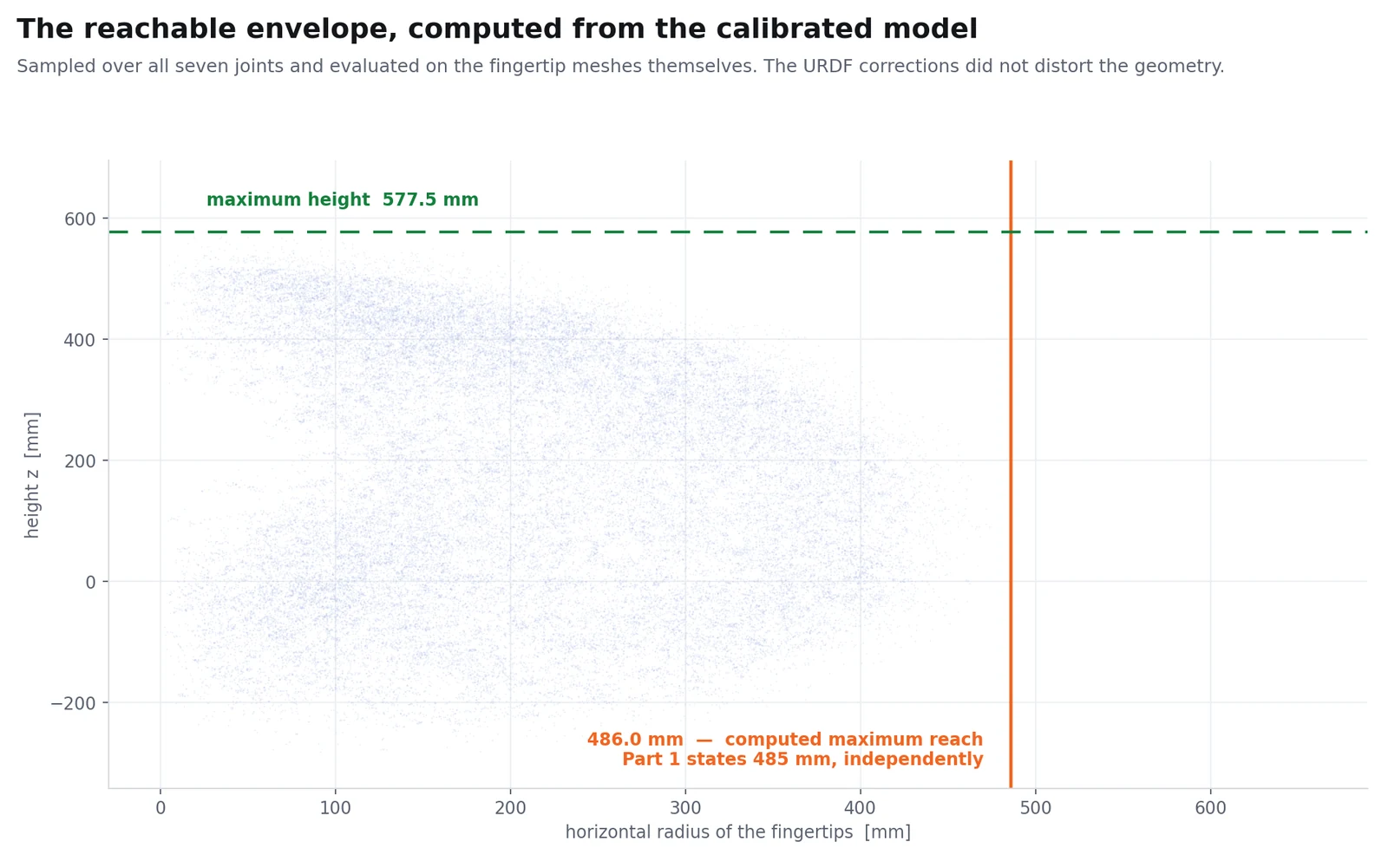
I computed forward kinematics from the calibrated URDF, optimised over all seven joints across their permitted ranges, and evaluated the position of every one of the 9 480 triangle vertices in the two fingertip meshes, with the mesh offsets taken from each link’s <visual><origin>. The largest horizontal radius any fingertip can reach:
486.0 mm.
Part 1 states a horizontal reach of 485 mm, derived independently from the CAD mass model. One millimetre apart, after four reversed axes and three rotated zeros. The corrections fixed the orientation without disturbing the geometry.
4. ros2_control: the layer that makes joints move
A controller in ROS 2 is not a PID loop, or not only that. It is a plugin with a fixed shape: it reads some state interfaces, writes some command interfaces, and gets called at a fixed rate by something that owns the clock. Everything else, how it decides what to write, is its own business.
The interfaces are the contract. A state interface is a named, typed value that flows from the hardware: Revolute 1/position, Revolute 1/velocity. A command interface is a named value that flows to it: Revolute 1/position. In the OmArm One’s description every arm joint exports exactly one command interface (position) and two state interfaces (position and velocity).
The piece that owns the clock is the controller manager. It runs a loop, and in each pass it does three things in a fixed order: it calls read() on the hardware, it calls update() on every active controller, and it calls write() on the hardware. That order is the reason the whole thing composes: every controller sees a consistent snapshot of the robot’s state, decides, and its decisions all leave together.
read() and write() are the two methods a hardware plugin must implement. The upstream documentation states the contract directly. For read(): “Read the current state values from the hardware. […] The data readings from the physical hardware has to be updated and reflected accordingly in the exported state interfaces.” For write(): “Write the current command values to the hardware. […] The physical hardware shall be updated with the latest value from the exported command interfaces.” Both receive “The time at the start of this control loop iteration” and “The measured time taken by the last control loop iteration”, and both are driven from the resource manager’s read and write loops: the controller manager orchestrates the cycle, the resource manager does the talking. The controller manager’s own update_rate parameter describes the loop in one line: “This loop reads states from hardware, updates controllers and writes commands to hardware.”
So the picture is:
                    controller manager  (100 Hz)
                             |
            +----------------+----------------+
            |                |                |
      read()           update() on          write()
            |          every controller        |
            v                                  v
   +--------------------------------------------------+
   |            hardware plugin                       |
   |   gz_ros2_control/GazeboSimSystem   (simulation) |
   |   omarm_hardware/OmArmSystem        (real arm)   |
   +--------------------------------------------------+
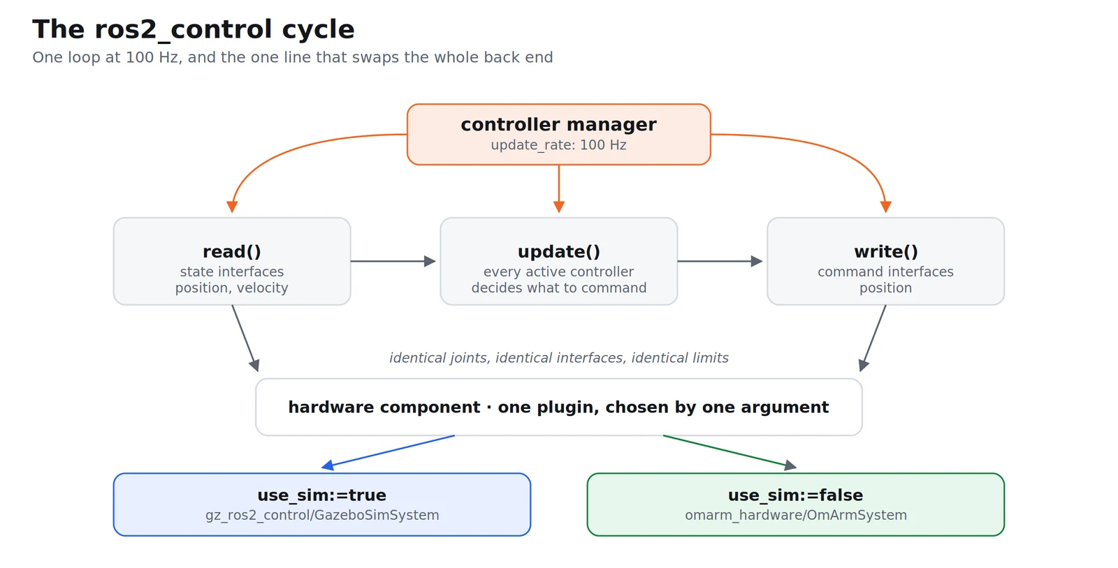
And here is the payoff, in one line of the OmArm One’s description:
<hardware>
  <xacro:if value="$(arg use_sim)">
    <plugin>gz_ros2_control/GazeboSimSystem</plugin>
  </xacro:if>
  <xacro:unless value="$(arg use_sim)">
    <plugin>omarm_hardware/OmArmSystem</plugin>
    <param name="device">auto</param>
    <param name="baudrate">115200</param>
    ...
  </xacro:unless>
</hardware>
Everything below that block (the joint names, the interfaces, the limits) is shared. One argument decides whether the commands end up in a physics engine or in an ESP32. A trajectory planned against the simulation runs unchanged on the arm, because nothing above the hardware plugin can tell the difference.
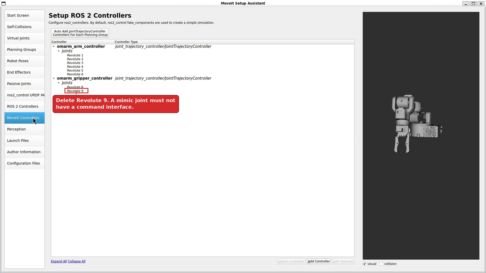
The seven joints listed in the block are Revolute 1 to Revolute 6 and Revolute 8. Revolute 9 is deliberately absent, and that is not a style choice: ros2_control states the rule outright. “The mimic joints must not have command interfaces but can have state interfaces.” The gear pair is one degree of freedom, so it gets one command.
5. The three controllers, and who orchestrates them
The configuration that the controller manager loads is omarm_moveit_config/config/ros2_controllers.yaml:
controller_manager:
  ros__parameters:
    update_rate: 100  # Hz

    omarm_arm_controller:
      type: joint_trajectory_controller/JointTrajectoryController
    omarm_gripper_controller:
      type: joint_trajectory_controller/JointTrajectoryController
    joint_state_broadcaster:
      type: joint_state_broadcaster/JointStateBroadcaster
Three controllers, and they do three different kinds of job.
joint_state_broadcaster is the odd one out: it writes no commands at all. It reads every state interface the hardware exports and republishes them as a sensor_msgs/JointState message on /joint_states. That topic is what robot_state_publisher consumes to build the TF tree, which is what RViz draws and what MoveIt uses to know where the robot is. Without this controller active, the model on screen is frozen no matter what the arm does. It is a broadcaster, not a controller, and the documentation is blunt about the difference: “Broadcasters are not real controllers, and therefore take no commands.”
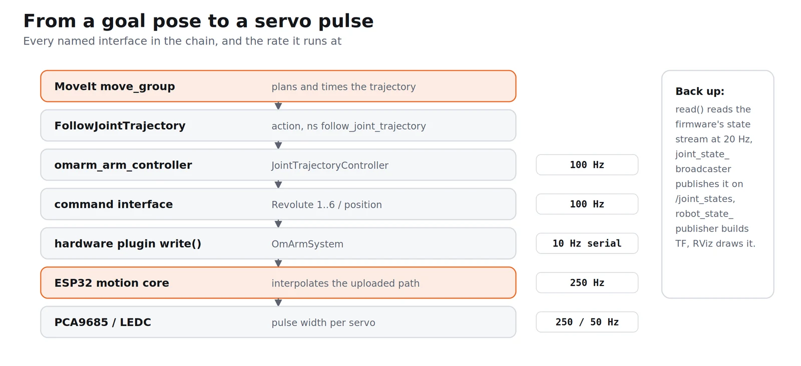
omarm_arm_controller is a JointTrajectoryController over the six arm joints. It takes a whole time-stamped path (joint positions with timestamps) and interpolates between the waypoints, writing a position command on every cycle of the control loop. It exposes that capability as a FollowJointTrajectory action, which is the interface MoveIt speaks.
omarm_gripper_controller is the same type over the single joint Revolute 8.
Both trajectory controllers are configured with position as the only command interface and position plus velocity as state interfaces, the same set the hardware exports, which is the condition for them to claim it at all.
On the MoveIt side, moveit_controllers.yaml names the same two controllers and tells MoveIt how to reach them:
moveit_controller_manager: moveit_simple_controller_manager/MoveItSimpleControllerManager
moveit_simple_controller_manager:
  controller_names: [omarm_arm_controller, omarm_gripper_controller]
  omarm_arm_controller:
    type: FollowJointTrajectory
    action_ns: follow_joint_trajectory
    default: true
    joints: ["Revolute 1", ..., "Revolute 6"]
So the chain of custody for a motion is: MoveIt plans a trajectory, hands it to omarm_arm_controller through a FollowJointTrajectory action, the controller interpolates it at 100 Hz and writes position commands, the hardware plugin’s write() turns those into whatever the back end needs, and joint_state_broadcaster carries the result back up so everyone can see where the arm is.
There is one deliberate exception on the real hardware, and section 14 explains why: the driver serves that action itself instead of letting a JointTrajectoryController do it.
6. Forward kinematics: what we have been doing all along
Every way the OmArm One has been driven so far is the same operation.
In Part 1 the web app showed seven sliders; each slider was a joint angle. In Part 1.5 the thumbsticks commanded joint velocities, which integrate into joint angles. In Part 2 the arm was moved by publishing a JointTrajectory message with six numbers in it: joint angles again. Different interfaces, one question: given the angles, where does the arm end up?
That is forward kinematics, and it is the easy direction because it is a chain of multiplications with exactly one answer. Each joint contributes a fixed transform (where the joint sits relative to the previous one) followed by a rotation about its axis by the current angle. Multiply them in order and you have the pose of the tool in the base frame.
In URDF terms each joint’s fixed part is <origin xyz rpy> and its variable part is a rotation about <axis>:
T_i = Trans(xyz_i) · Rot_rpy(rpy_i) · Rot_axis(axis_i, q_i)
T_tool = T_1 · T_2 · … · T_6 · T_fixed
One detail here is worth getting right, because everything downstream inherits it: what rpy means. The ROS wiki is the normative reference, but it is currently behind an anti-bot wall, so I read the parser instead. In urdfdom_headers, Rotation::setFromRPY(roll, pitch, yaw) builds the quaternion product q_z(yaw) · q_y(pitch) · q_x(roll), which is
R = Rz(yaw) · Ry(pitch) · Rx(roll)
— fixed-axis rotations applied in the order X, then Y, then Z. And urdf_parser/src/pose.cpp hands the three numbers of the attribute to that function positionally, so the first number is roll, the second pitch, the third yaw.
Two more things the parser source settles, which matter later: the parser does not normalise <axis> (the word normalize does not appear in joint.cpp — consumers normalise it, the file keeps whatever you wrote), and in <limit> the attributes effort and velocity are required: omit either and parsing fails outright, while lower and upper quietly default to 0.
I implemented the chain above and checked it against scipy.spatial.transform.Rotation: from_euler('xyz', …) over 2000 random angle triples agreed to 5.55 · 10⁻¹⁶, and the axis-angle rotation against from_rotvec to 9.99 · 10⁻¹⁶. That is machine precision, and it means the numbers in the rest of this post are computed in the same convention the URDF parser uses.
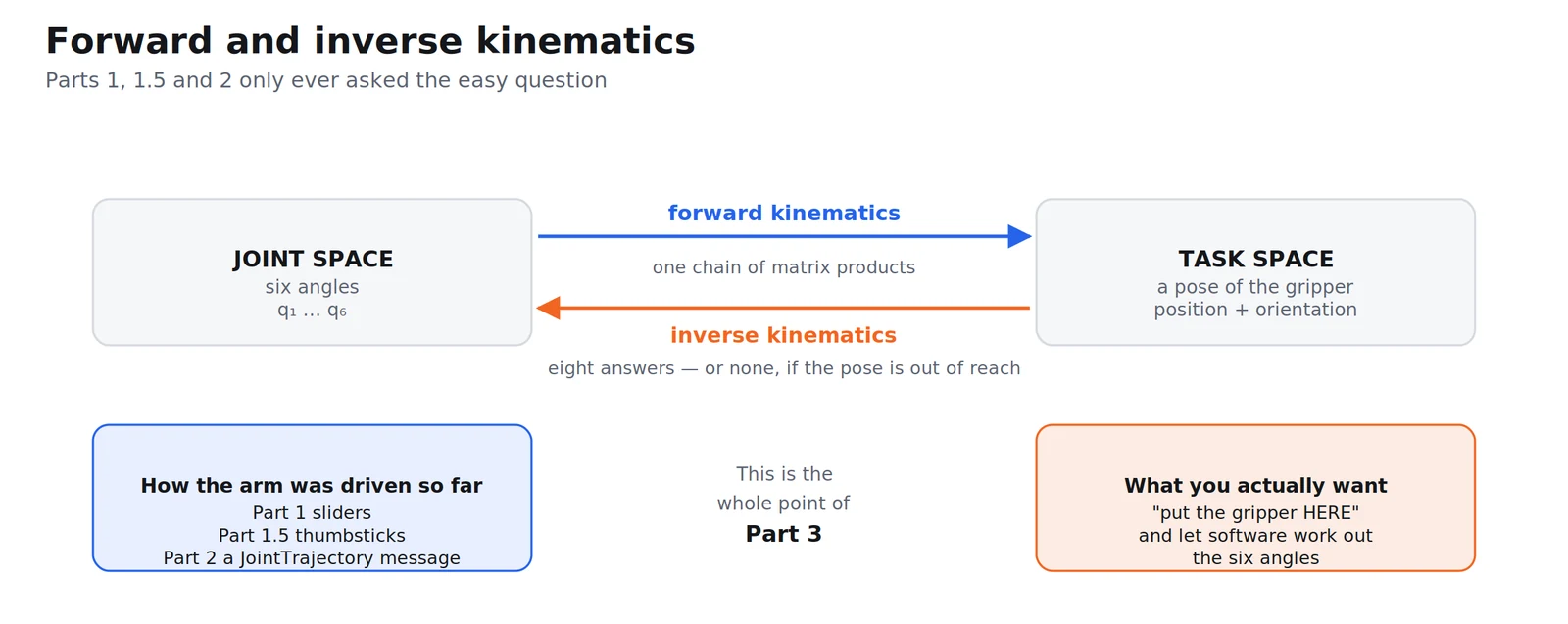
Forward kinematics is also what robot_state_publisher has been doing since Part 2. It is not a new idea, it is the thing that was drawing your arm in RViz all along. The new idea is running it backwards.
7. Denavit–Hartenberg, derived from the URDF
The next two sections are the derivation. They work out, by hand, the mathematics that MoveIt performs for you. Nothing later in this post depends on them: if you want the arm moving today, go straight to section 9 and come back when you are curious about what the solver is doing. If you want to know why it works, read on.
A URDF describes a robot in a way that is convenient to write: every joint carries its own little transform, in whatever frame the CAD happened to use. That is fine for drawing, and awkward for algebra. The Denavit–Hartenberg convention describes the same robot with the minimum number of parameters (four per joint instead of six) by choosing the coordinate frames rather than accepting them.
The four parameters, and what each one is:
| Parameter | Name | Meaning |
|---|---|---|
| joint offset | distance between the coordinate systems along the current joint axis (variable for a prismatic joint) | |
| joint angle | rotation about the current joint axis (variable for a revolute joint) | |
| link length | the shortest distance — the common normal — between the previous joint axis and the new one | |
| link twist | the angle between the two joint axes, measured about that common normal |
The transform from frame to frame is then always the same four operations:
The reason this convention exists is that it forces every joint into an identical shape, which is what makes a general inverse-kinematics derivation possible at all.
Deriving the table
You do not guess these numbers, you construct them. The procedure:
- Write each joint axis as a line in the base frame (a point it passes through and a unit direction) with all joint angles at zero.
- For each consecutive pair of axes, find the common normal: the unique line segment perpendicular to both. Its length is , its direction becomes the axis of the frame.
- Place frame with its along joint axis and its origin at the foot of that common normal.
- Read and off as the translation and rotation along and about the previous .
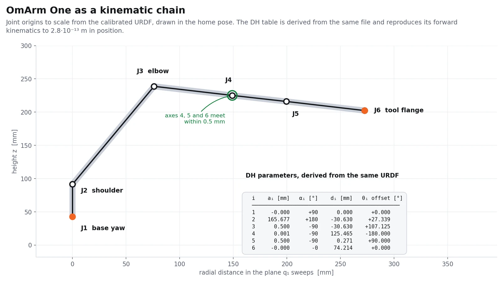
Applied to the calibrated omarm.xacro, that gives:
| i | [mm] | [°] | [mm] | offset [°] |
|---|---|---|---|---|
| 1 | 0.000 | +90.000 | 0.000 | 0.000 |
| 2 | 165.677 | 180.000 | −30.630 | +27.339 |
| 3 | 0.500 | −90.000 | −30.630 | +107.125 |
| 4 | 0.001 | −90.000 | +125.465 | −180.000 |
| 5 | 0.500 | −90.000 | +0.271 | +90.000 |
| 6 | 0.000 | 0.000 | +74.214 | 0.000 |
Checking it two ways
A DH table that is nearly right is worse than none, so both checks are worth stating.
First: every relative transform between consecutive DH frames has to fit the four-parameter form exactly. If the frames were placed wrongly there would be a residual: a translation along , say, which the form cannot express. The maximum residual across all six links is 0, to machine precision.
Second: forward kinematics computed from the table has to reproduce forward kinematics computed directly from the URDF. Over 5 000 random joint configurations the tool position agrees to 2.8 · 10⁻¹³ m and the rotation matrix to 3.8 · 10⁻¹² (a ratio, not a length). The table is not an approximation of the URDF, it is a rewriting of it.
What the table says about the arm
mm is the upper arm. mm is the forearm. mm is the distance from the wrist centre to the tool flange.
and are both −30.630 mm, and flips the sign of the second one. They cancel. In the language of arm design, the OmArm One has no shoulder offset, which is not obvious from looking at it, and which makes the inverse kinematics considerably nicer.
And then the four small numbers: , , and mm. In an arm with a true spherical wrist (three axes meeting at one point), all four would be exactly zero. Measured directly, the common normals between the wrist axes are:
| axis pair | distance |
|---|---|
| 4 ↔ 5 | 0.001 mm |
| 5 ↔ 6 | 0.500 mm |
| 4 ↔ 6 | 0.271 mm |
Half a millimetre. That is the same order as the rounding in the file itself: rpy values are written with six decimal places, so π/2 appears as 1.570796 instead of 1.5707963…, and errors of that size propagate into the geometry.
8. Inverse kinematics in closed form
Set those four small numbers to zero and the OmArm One becomes, exactly, an anthropomorphic 6R arm with a spherical wrist, the configuration for which a closed-form solution has been known for decades. The question is what that idealisation costs.
Measured over 20 000 random joint configurations, comparing the tool pose of the idealised model against the exact one:
| position error | mean 0.843 mm, median 0.895 mm, max 1.069 mm |
| orientation error | 0.0000° |
Orientation is untouched because only lengths were zeroed, not axis directions. Just over a millimetre of position, worst case. Keep that number; it comes back at the end of the section.
Step 1: the wrist centre
A spherical wrist means joints 4, 5 and 6 all rotate about axes through one point. That point, the wrist centre, depends only on joints 1, 2 and 3, which is what makes the problem tractable: position and orientation decouple.
From a target tool pose :
where is the fixed transform from the DH end frame to tool_link_1, and is the third column of the rotation of , the approach axis. Back off mm along it and you are at the wrist centre.
Step 2: joints 1 to 3, from the position
Working the geometry symbolically for the idealised table gives, with mm, mm, and :
Verified against the numerical forward kinematics over 3 000 configurations: largest disagreement 4.72 · 10⁻¹⁶ m.
The structure of the first line is the whole story. and carry the same factor , which says the wrist centre always lies in the vertical plane that sweeps. That is the formal statement of “no shoulder offset”, and it means comes straight out of the target with no correction term:
(atan2 is the two-argument arctangent every language ships. It takes the two coordinates separately rather than their ratio, so it knows which quadrant the angle is in — which plain atan cannot.)
Two branches, because the arm can reach the same point facing forwards or reaching backwards over its own shoulder.
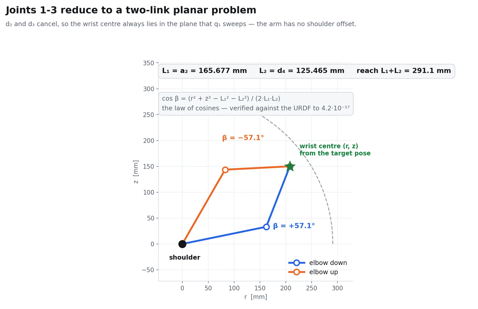
With fixed, project the wrist centre into that plane — , signed, and — and what is left is the oldest problem in robotics: a two-link planar arm. Squaring and adding the two equations above collapses them into
which is the law of cosines wearing a different hat. (Checked over 5 000 value pairs: largest deviation 4.16 · 10⁻¹⁷. And is exactly the offset of joint 3 in the DH table — the table and the equation close on each other.)
So depends only on how far away the target is, never on the direction. Solve it with the standard construction:
The in is elbow-up and elbow-down. If the target is out of reach and there is no solution at all, which is the honest answer, and one a numerical solver can only give you by failing to converge.
Step 3: joints 4 to 6, from the orientation
Joints 1 to 3 have used up the position. What is left for the wrist is the rotation
and for the idealised chain that product has the form
This looks like it needs its own derivation, and it does not, because of one identity — which I checked numerically rather than trusting it:
Substitute it and move the constant to the left-hand side:
That is an ordinary ZYZ Euler decomposition, which every linear algebra library can do. With and from the DH table:
and the second ZYZ branch gives the flipped wrist.
The eight solutions, and whether they work
Two shoulder branches × two elbow branches × two wrist branches = eight solutions for any reachable pose. In the test below, every single target produced exactly eight: minimum 8, maximum 8, mean 8.0 over 2 000 targets.
The test itself: pick a random joint configuration, compute its tool pose, throw away the angles, solve the inverse problem from the pose alone, then run forward kinematics on the answer and compare.
| Check | Position error | Orientation error |
|---|---|---|
| against the idealised model | max 6.48 · 10⁻¹³ mm | max 2.7 · 10⁻⁶ ° |
| the same solution on the exact URDF model | max 1.0684 mm, mean 0.7316 mm | 0.00000° |
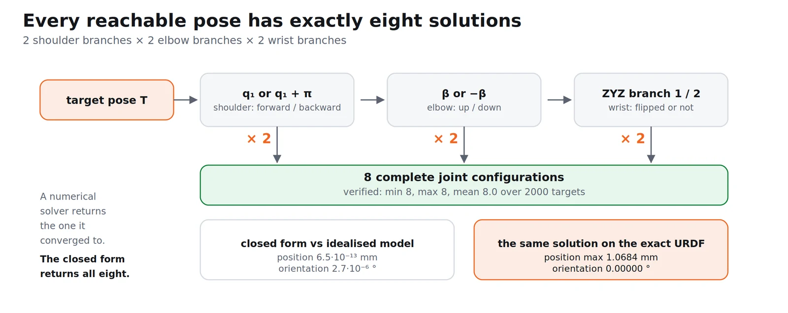
The closed form is mathematically exact. The price of ignoring the wrist’s half millimetre is at most 1.07 mm at the tool.
For a printed arm that is nothing, and it is worth seeing why with numbers rather than a shrug.
The PCA9685 divides its period into 4096 counts, and its prescaler is an integer. Asking for 250 Hz off a 25 MHz oscillator gives prescale 23, and the chip actually runs at 254.31 Hz: a period of 3932.16 µs, so 1.0417 counts per microsecond. The servo’s 500–2500 µs range is therefore 2083 counts for 180°, which is 0.0864° per count. At the 291.142 mm lever formed by , one count moves the wrist centre 0.44 mm.
So the worst-case error of the closed-form solution is about two and a half counts of the PWM chip, before the servo’s own deadband, the backlash in a printed gear, or the flex in a PLA link. The idealisation is not the limiting factor in this machine, and it is not close to being one.
9. Why MoveIt solves it numerically anyway
The last two sections derived an exact, closed-form answer for this arm. MoveIt uses none of it. The configuration it actually loads is four lines:
omarm_arm:
  kinematics_solver: kdl_kinematics_plugin/KDLKinematicsPlugin
  kinematics_solver_search_resolution: 0.005
  kinematics_solver_timeout: 0.05
KDL is a numerical solver. It iterates, on the exact geometry of the URDF (including the half millimetre) until it converges or the 50 ms timeout runs out.
That is the right default, and the closed form above is still worth having. Three reasons.
A numerical solver works on any chain you hand it, without anyone deriving anything. Change a link length, add a tool, and it keeps working. A closed-form solver is a piece of code that encodes one specific geometry, and every edit to the URDF invalidates it silently.
The closed form tells you things the numerical one cannot. Eight solutions, exactly, always: a numerical solver returns the one it happened to converge to. Out of reach is a clean algebraic fact rather than a timeout. And the derivation is what proves the arm is solvable at all.
And when you do want closed form in production, you generate it rather than write it. MoveIt ships tooling for exactly that: “MoveIt provides tools to generate an IKFast kinematics plugin for MoveIt using the OpenRAVE generated cpp files”, driven by auto_create_ikfast_moveit_plugin.sh, which takes the robot and the chain as arguments:
ros2 run moveit_kinematics auto_create_ikfast_moveit_plugin.sh \
  --iktype Transform6D \
  omarm.urdf omarm_arm base_link tool_link_1
The generated plugin replaces the kinematics_solver line. That is the right move when 50 ms of iteration per query is too slow. For an arm moving at 50 °/s, it is not.
10. After IK: trajectories and time parameterization
Inverse kinematics answers one question: which joint angles put the gripper there. It says nothing about how to get from here to there, and nothing about when.
That gap is bigger than it sounds. Suppose you solve IK for the target and command those six angles directly. Every joint starts at once and runs at whatever speed it can manage, so the fast joints arrive early and the slow ones drag. The gripper’s path through space is whatever falls out of that: not a line, not an arc, just a curve nobody chose. Along the way it may pass through the table. And the arm snaps into motion at full acceleration, which on a printed arm with plastic horns is how you strip a gear.
Three separate problems, three separate layers.
Path planning picks the sequence of configurations from start to goal that keeps the robot out of collision: with the world, and with itself. For a 6-DOF arm this is a search in a six-dimensional space where the forbidden regions have no simple shape, which is why the standard answer is sampling-based: scatter random configurations, keep the collision-free ones, connect them into a graph, find a path through it. OMPL is the library of those planners that MoveIt uses by default.
Trajectory optimization takes a path that works and makes it better: shorter, smoother, further from obstacles. A sampled path is valid but rarely elegant; it wanders, because random points do. Shortcutting and smoothing passes clean that up.
Time parameterization is the last step and the one people forget. Up to here the path is a list of configurations with no clock attached. Time parameterization assigns each waypoint a timestamp such that no joint ever exceeds its velocity or acceleration limit — which is exactly why those limits have to be honest, and exactly why velocity="100" from the CAD export was dangerous rather than merely wrong. Feed a planner a limit nineteen times higher than the motor can deliver and it will produce a beautifully timed trajectory the arm cannot follow.
The limits the OmArm One hands to that step live in joint_limits.yaml:
default_velocity_scaling_factor: 0.50
default_acceleration_scaling_factor: 0.50

joint_limits:
  "Revolute 1":
    has_velocity_limits: true
    max_velocity: 1.75          # rad/s = 100.3 deg/s
    has_acceleration_limits: true
    max_acceleration: 3.5       # rad/s^2
  ...
  "Revolute 8":
    max_velocity: 3.0           # rad/s = 171.9 deg/s
    max_acceleration: 8.0
Two things to read here. The arm joints are capped at 1.75 rad/s, a third of what the URDF permits (5.2 rad/s) and well under the DS3240’s 300 °/s no-load figure, because a loaded arm is not an unloaded one. And the scaling factors are the dial you actually turn day to day: 0.50 means “plan at half the stated limits”. Raising them is a two-line change, and lowering them is the first thing to try when a move looks violent.
The gripper is allowed to be quicker than the arm (3.0 rad/s against 1.75) because it carries no arm weight, and because a slow gripper is what makes a pick look sluggish even when the arm itself is fast.

11. What MoveIt actually is
MoveIt is not one algorithm. It is the assembly of everything in the last five sections into a single service, and the reason it is worth using is that the pieces have to agree with each other and doing that by hand is where projects die.
What it holds together:
- the robot model, read from the same URDF as everything else, plus a semantic layer (the SRDF) that says which joints form an arm, which links form a gripper, and which pairs of links can never touch;
- a planning scene (the robot plus whatever else is in the world), which is what collision checks run against;
- kinematics, the IK plugin from section 9;
- planners behind one interface: “MoveIt integrates directly with OMPL and uses the motion planners from that library as its primary/default set of planners”, with the Pilz industrial motion planner and CHOMP also available by default;
- time parameterization, section 10;
- execution, which hands the finished trajectory to a controller through
FollowJointTrajectoryand monitors it.
From the outside, move_group is one node that takes “put the gripper here” and returns either a timed, collision-free trajectory or a refusal. Everything in sections 6 to 10 happens inside it, which is why the demo at the end looks like nothing is happening: you drag a marker, the arm moves, and the IK, the sampling, the smoothing and the timing are all invisible.
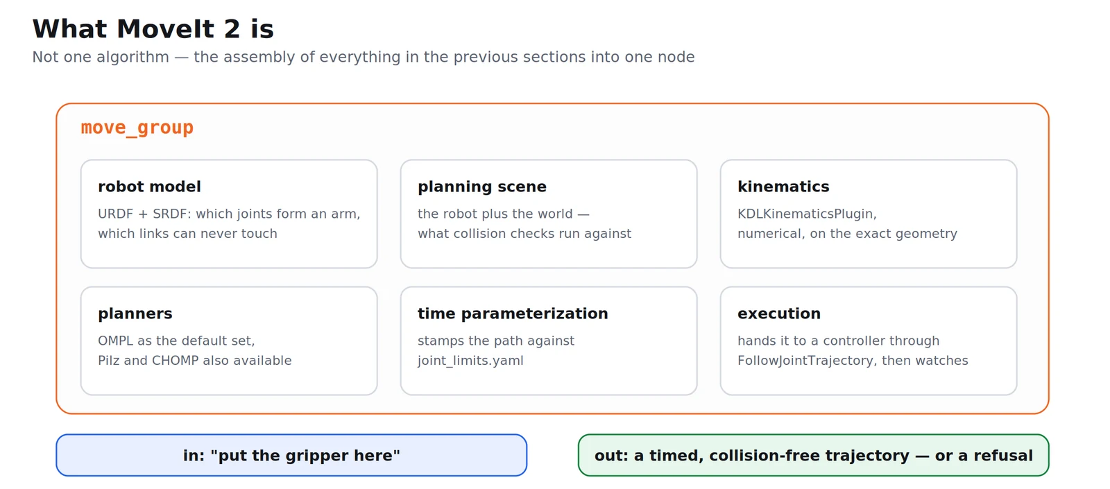
That invisibility is exactly why the previous sections exist. When it works, you do not need to know. When it does not — when the planner reports failure on a pose that is clearly reachable, or the arm takes a bizarre route to a point right in front of it — the fault is always in one of those layers, and you cannot debug a layer you have never seen.
12. Building the configuration package with the Setup Assistant
MoveIt’s configuration is a package of YAML and launch files. You can write it by hand; nobody does, because the Setup Assistant generates it from the URDF and then you correct the two or three things it got wrong.
Launch it with:
ros2 launch moveit_setup_assistant setup_assistant.launch.py
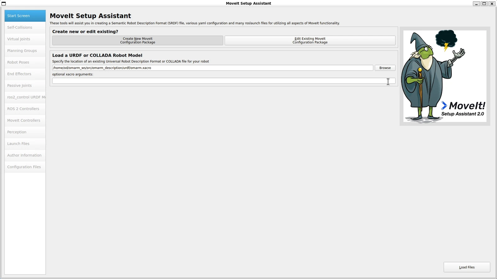
Start screen
Choose Create New MoveIt Configuration Package and point it at the xacro — the calibrated one, not the export. Everything the assistant generates inherits the model’s mistakes, so the audit in section 3 has to come first.
Self-collisions
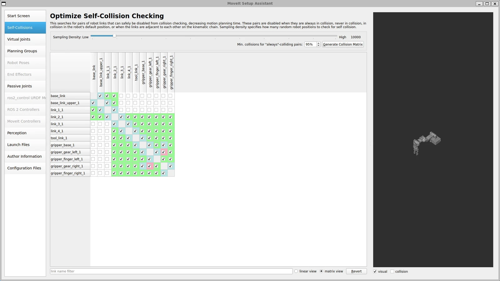
The assistant samples the joint space and works out, for every pair of links, whether they can ever touch. Pairs that are always in collision, never in collision, adjacent in the chain, or in collision in the default pose get written into the SRDF as disable_collisions entries with a reason.
This is not cosmetic. Every pair that stays enabled is checked on every collision query, thousands of times per plan. The OmArm One’s SRDF ends up with 42 disabled pairs: 11 tagged Adjacent, 30 Never and one Default.
Virtual joints
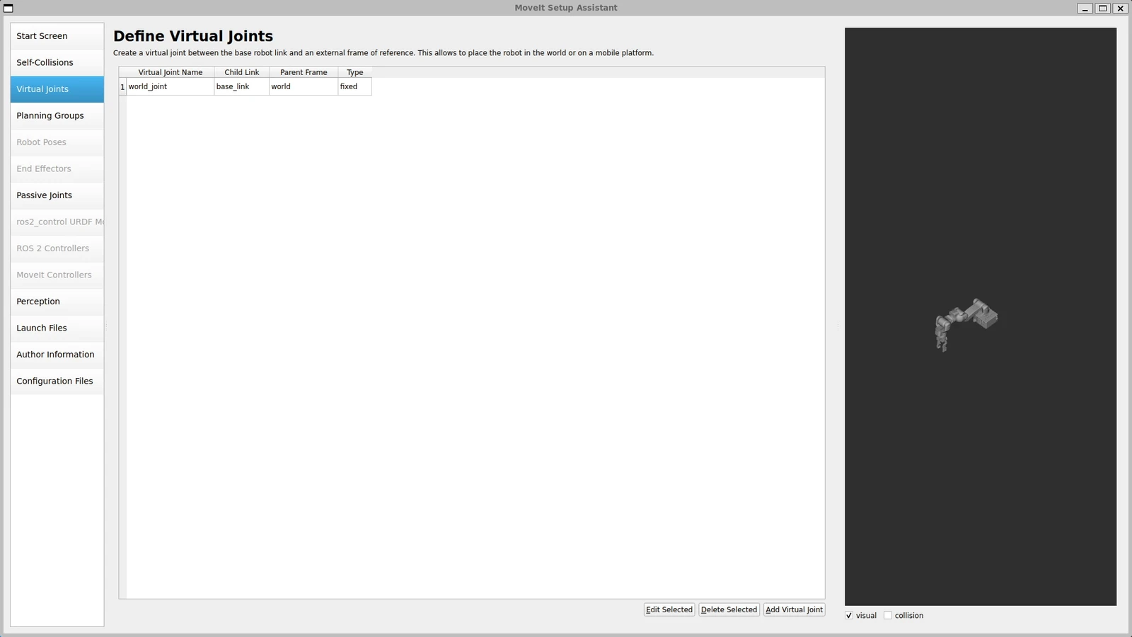
A virtual joint connects the robot’s base to something outside the robot. The OmArm One is bolted to a table, so it gets one fixed joint from world to base_link. In the generated SRDF:
<virtual_joint name="world_joint" type="fixed" parent_frame="world" child_link="base_link"/>
If your arm sits on a mobile base, this is where that would be a floating or planar joint instead.
Planning groups
A planning group is the set of joints a planner is allowed to move. The OmArm One gets two.
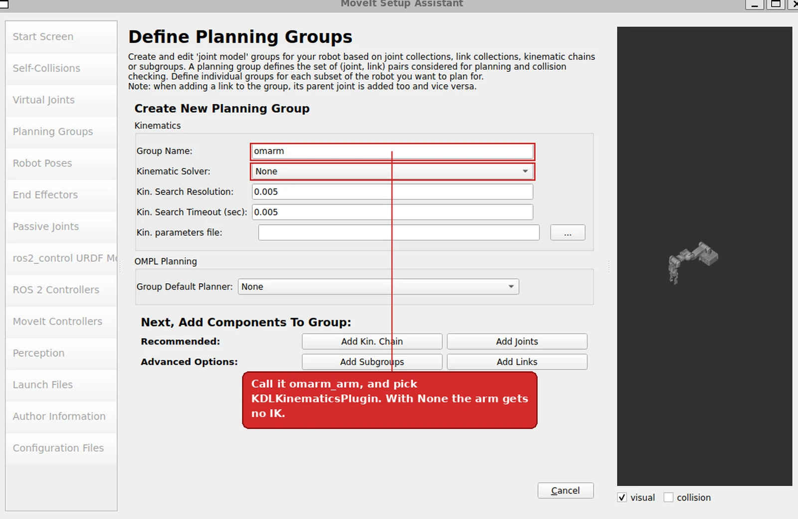
omarm_arm is defined as a kinematic chain from base_link to tool_link_1. Defining it as a chain rather than a list of joints is what lets MoveIt attach an IK solver to it: a solver needs a base and a tip, not a bag of joints.
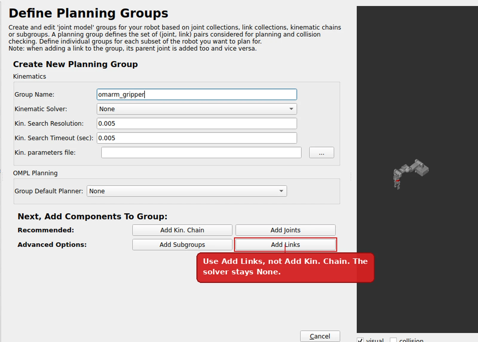
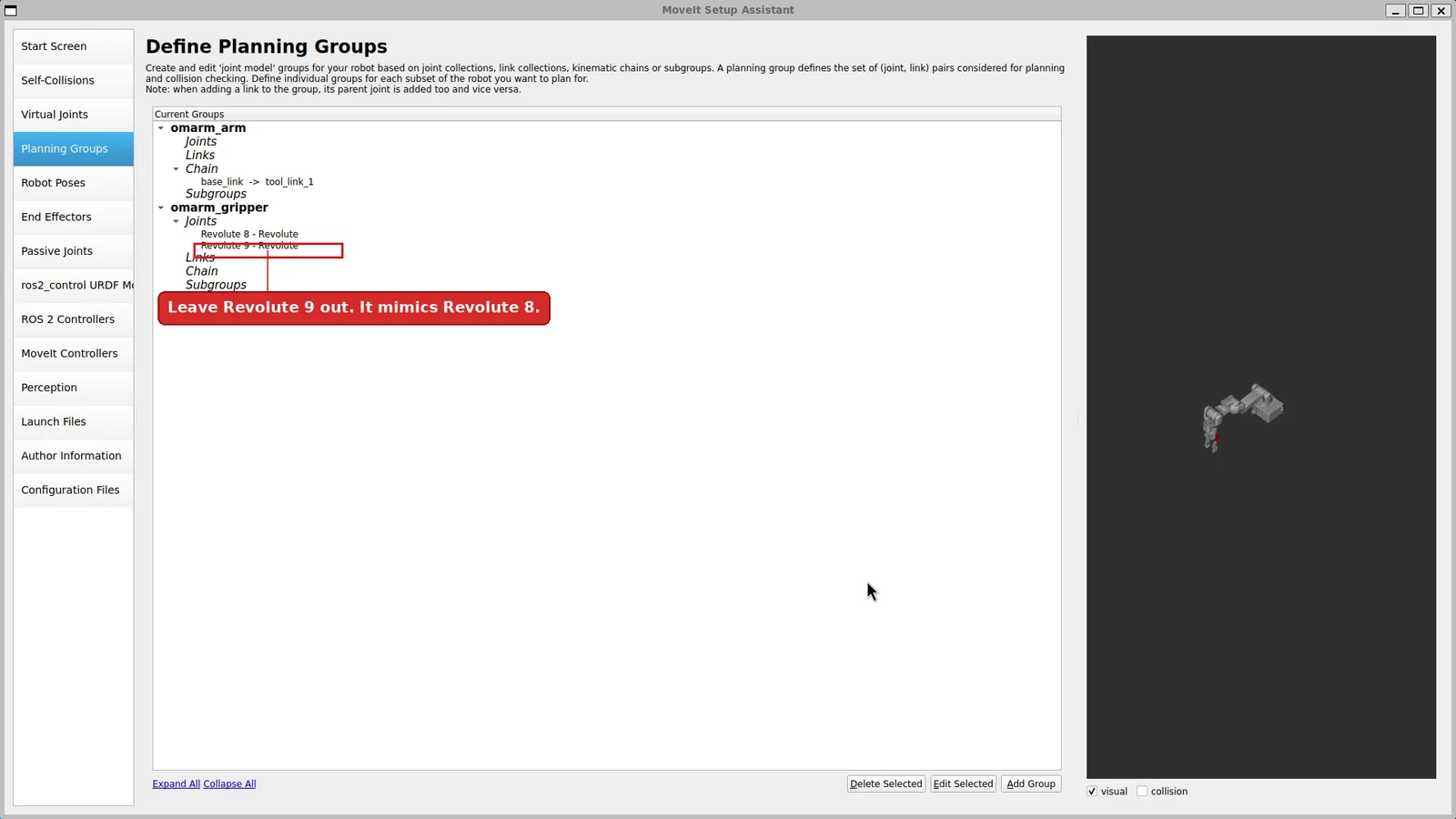
omarm_gripper is defined by its links plus the joint Revolute 8. Listing the links matters: without them the group has no geometry, and the end-effector’s interactive marker in RViz ends up with no usable size or pose, drawn near the model root instead of at the gripper. It looks like a loose part floating next to the base, and the cause is an empty link list.
The kinematic solver dropdown is where KDL gets selected for the arm group; the gripper group needs none, because nothing plans a pose for it.
Both groups finished, as the assistant lists them:
Robot poses
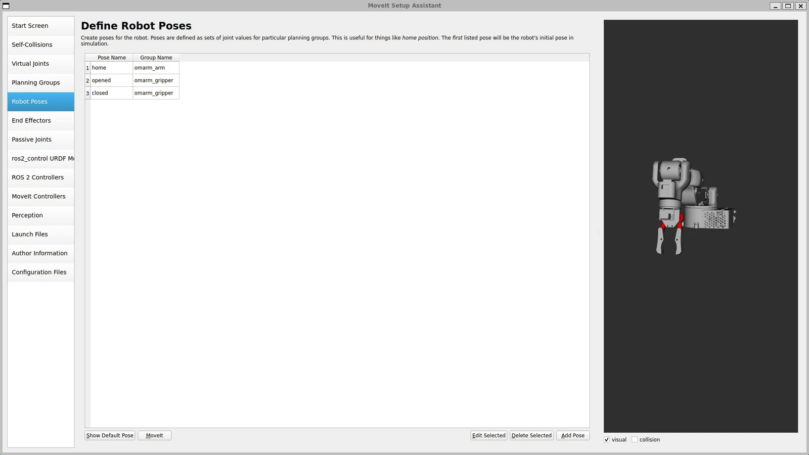
Named configurations, so that “go home” is one call instead of six numbers. The OmArm One defines three:
<group_state name="home" group="omarm_arm">
  <joint name="Revolute 1" value="1.5707"/>  ...
</group_state>
<group_state name="opened" group="omarm_gripper">
  <joint name="Revolute 8" value="1.1236"/>
</group_state>
<group_state name="closed" group="omarm_gripper">
  <joint name="Revolute 8" value="0"/>
</group_state>
opened is 1.1236 rad, which is 64.4°. The joint’s limit is 1.6 rad (91.7°), so that leaves 27° of reserve before the mechanical end — deliberately, because driving a servo into its stop is how you burn it out while it is sitting still.
End effectors — and the error worth showing
This is the step that fails, and the failure is instructive.
The obvious entry is: end effector gripper, group omarm_gripper, parent link gripper_base_1, the link the gripper is bolted to.
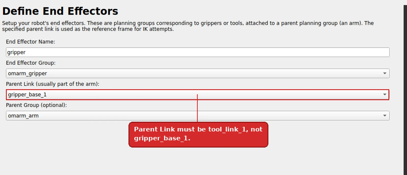
The assistant refuses:
The specified parent group ‘omarm_arm’ must contain the specified parent link ‘gripper_base_1’.
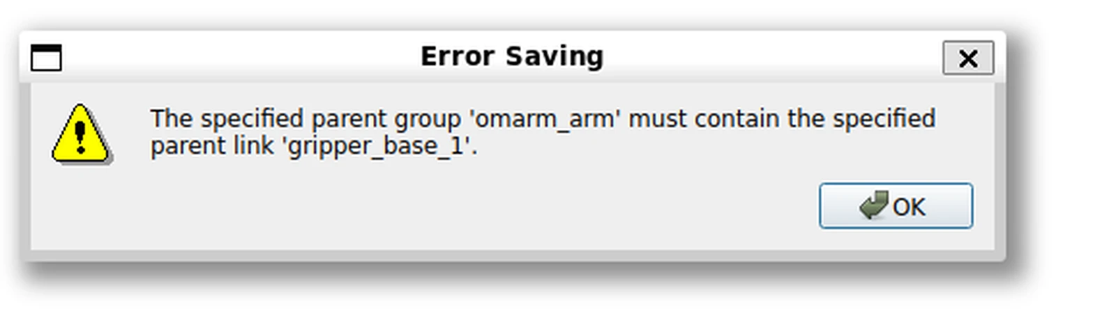
The message is exactly right and easy to misread. The arm group was defined as the chain base_link → tool_link_1. gripper_base_1 is one fixed joint beyond the tip, so it is not in the arm group. The parent link of an end effector has to be a link the arm group owns, because that link is the frame IK aims at.
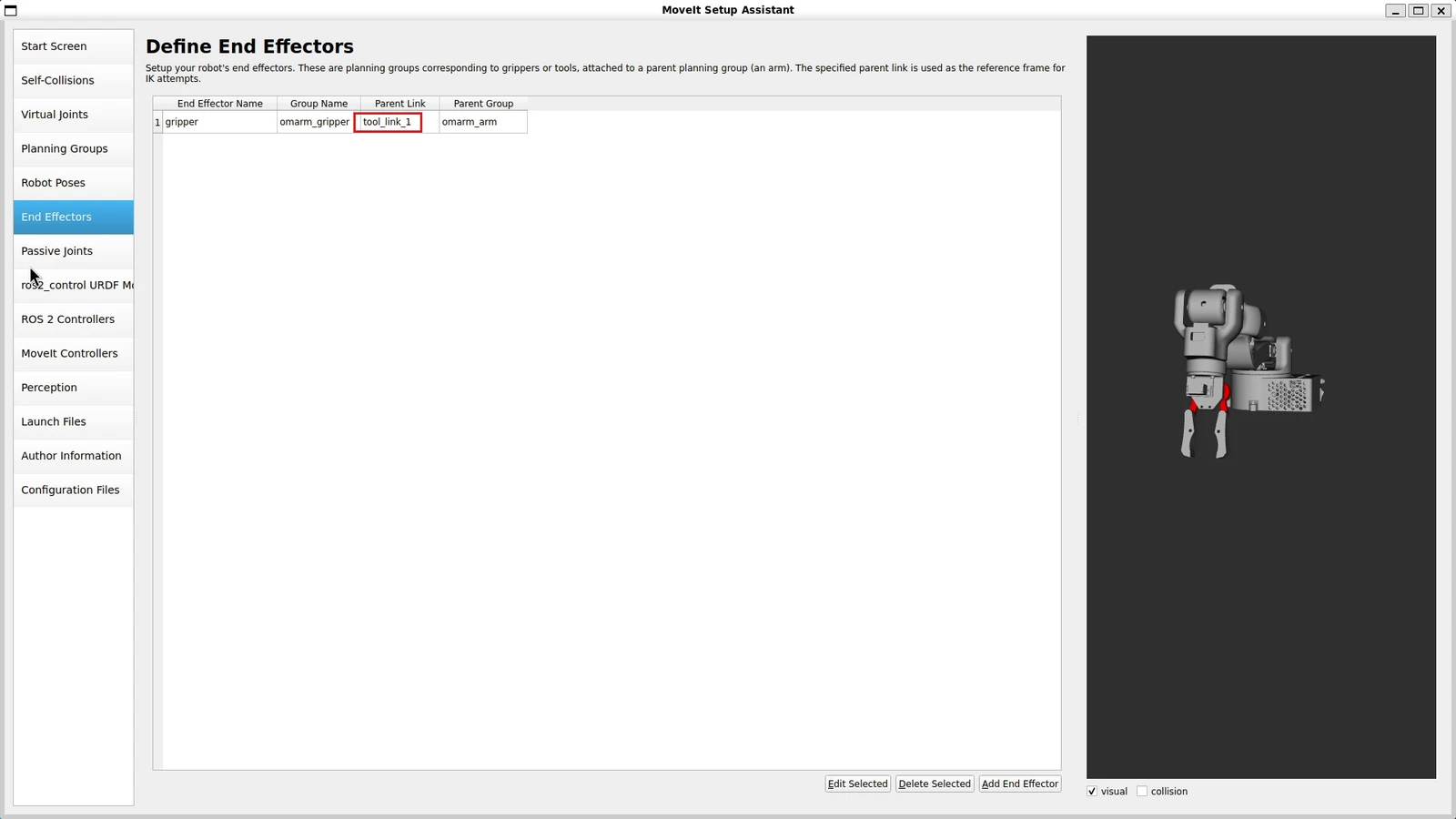
The fix is one word: parent link tool_link_1. Which is what the finished SRDF contains:
<end_effector name="gripper" parent_link="tool_link_1" group="omarm_gripper" parent_group="omarm_arm"/>
Passive joints
Joints that are not actuated and whose state nobody publishes. The OmArm One has none in this sense: Revolute 9 is coupled to Revolute 8 through the mimic tag in the URDF, which is a different mechanism and is handled there.
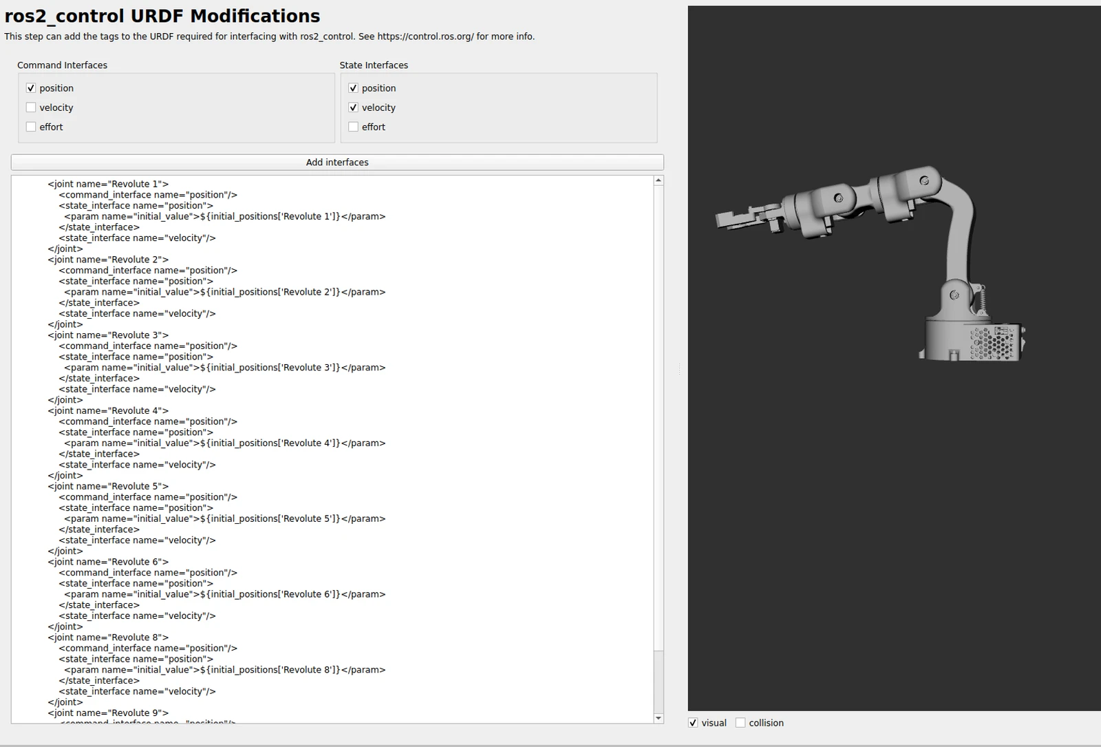
ros2_control URDF modifications
The assistant can write the <ros2_control> block for you. Tick position under command interfaces, and position and velocity under state interfaces, matching what the joints actually offer.
Treat the generated block as a starting point. The version this workspace ships is hand-written on top of it, because the generated one has no notion of two interchangeable back ends, no hardware parameters, and no per-joint calibration.
ROS 2 controllers and MoveIt controllers
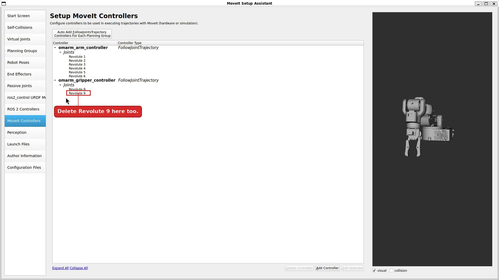
Two separate screens for two separate files. ROS 2 Controllers writes ros2_controllers.yaml, which is what the controller manager loads. MoveIt Controllers writes moveit_controllers.yaml, which is how MoveIt finds them. The button on each screen adds one controller per planning group, which for the OmArm One is the right answer: omarm_arm_controller over Revolute 1–6, omarm_gripper_controller over the gripper.
Launch files, author information, generate
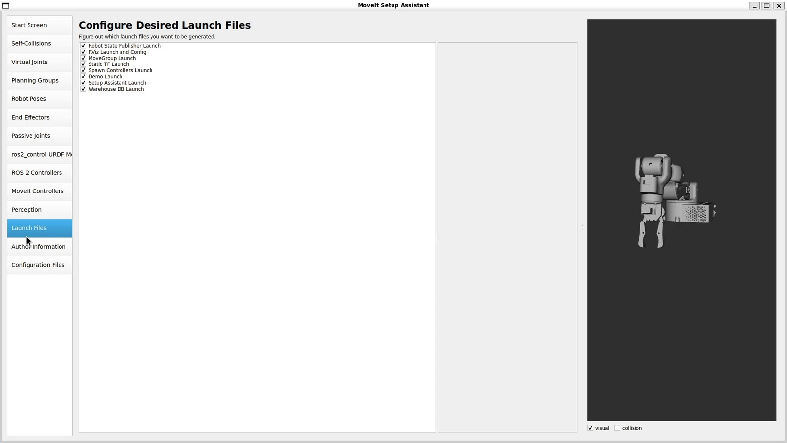
Leave the launch file selection at its defaults. Fill in the author fields: the package will not generate without them. Then pick an output directory and generate.
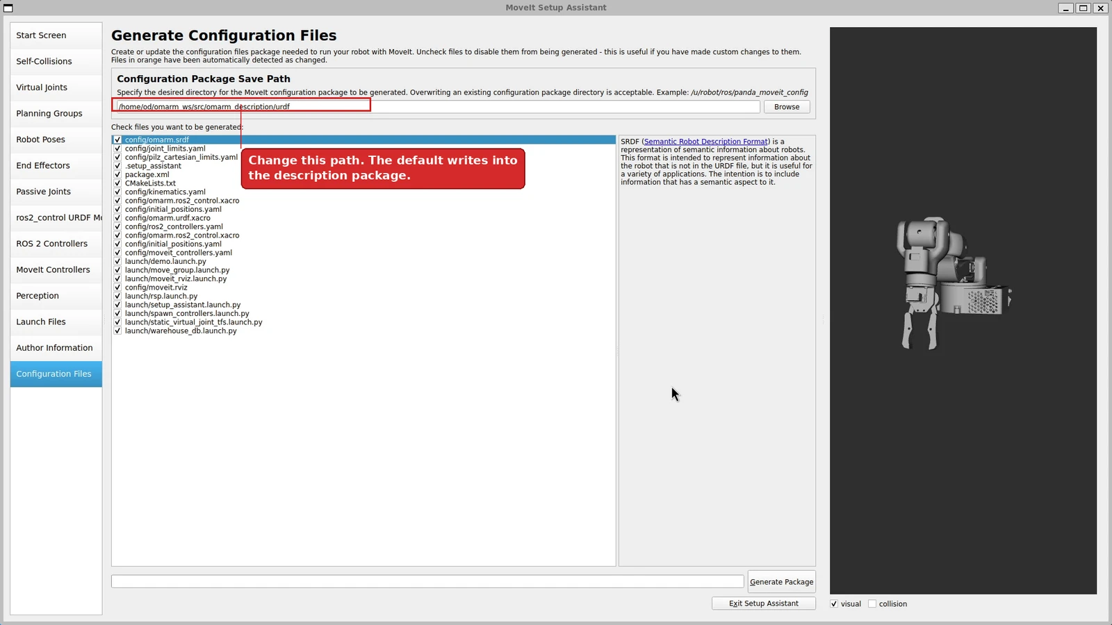
The one field worth a second look is the save path. The assistant offers a directory inside the description package; the configuration belongs in its own package instead.

Build and source:
colcon build --packages-select omarm_moveit_config
source install/setup.bash
13. MoveIt in RViz and Gazebo
The generated package brings its own demo launch:
ros2 launch omarm_moveit_config demo.launch.py
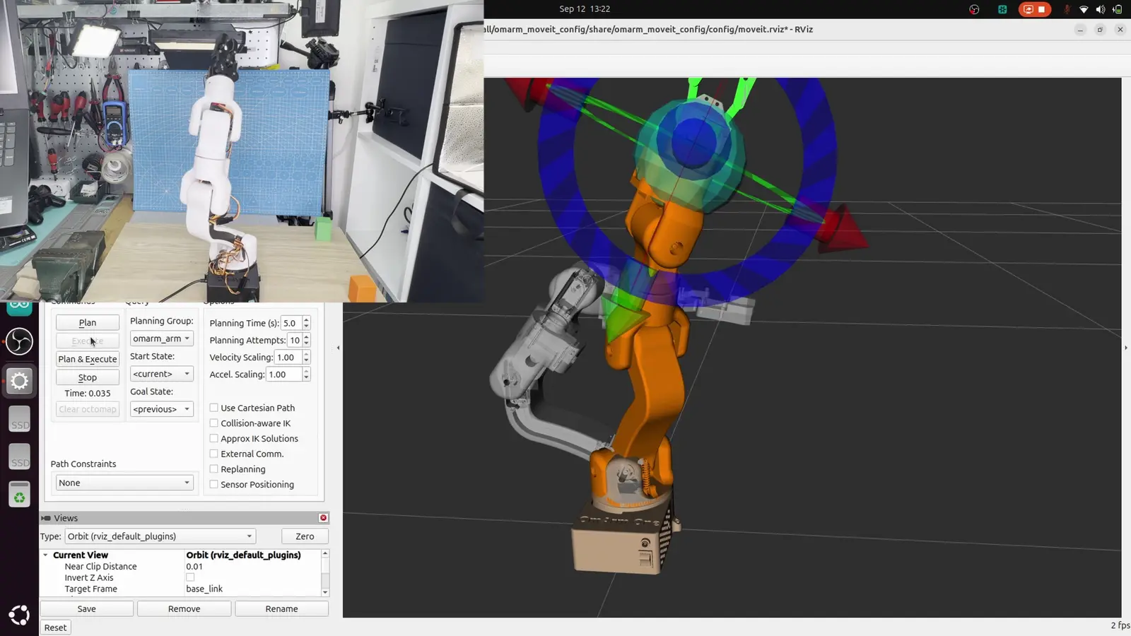
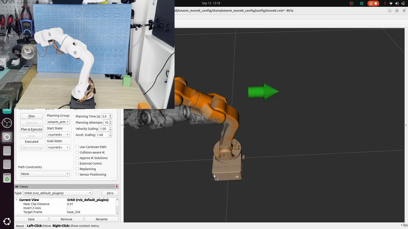
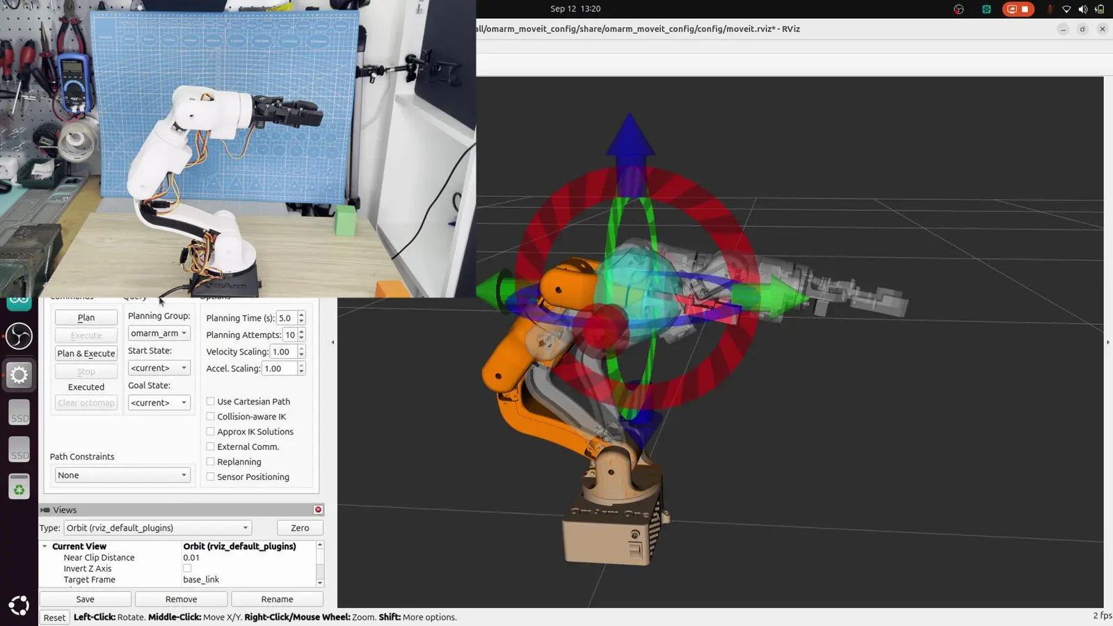
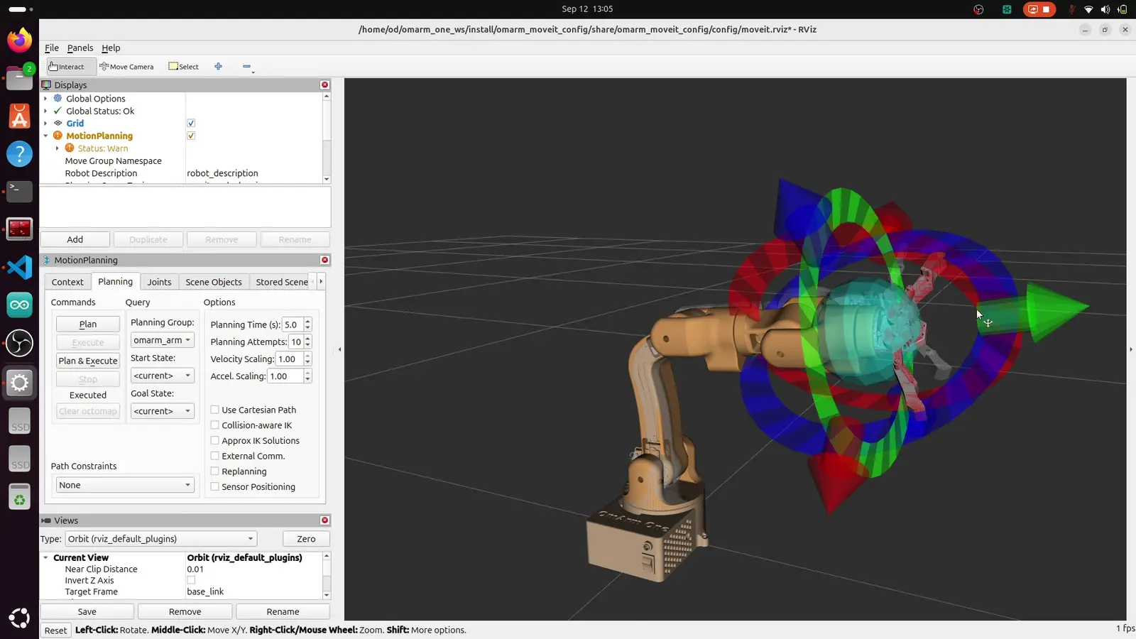
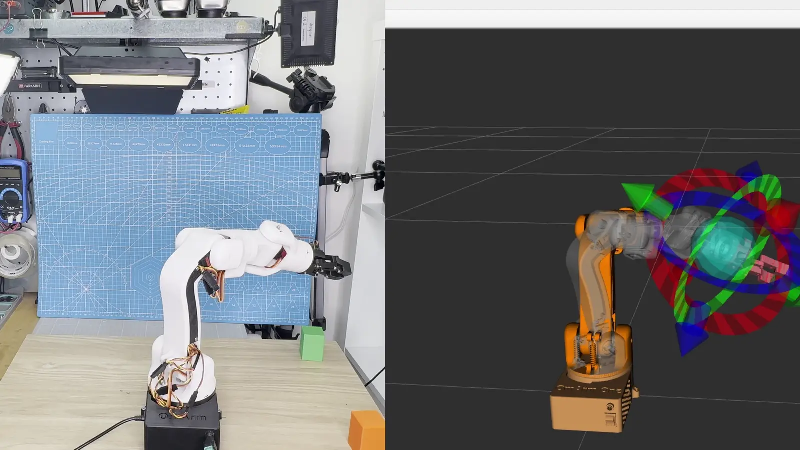
RViz opens with the MotionPlanning panel. Two robots are drawn on top of each other: the current state, and an orange ghost that is the goal. Drag the interactive marker at the gripper, press Plan, and the ghost walks through the planned trajectory. Press Execute and the real state follows.
Every one of the last eight sections is running inside that one drag. The marker gives a pose. MoveIt calls KDL for IK. The planner samples a collision-free path. The smoother tidies it. Time parameterization stamps it against joint_limits.yaml. The result goes to omarm_arm_controller as a FollowJointTrajectory goal, the controller interpolates at 100 Hz, and joint_state_broadcaster carries the state back so RViz can draw it.
For physics, the same configuration launches against Gazebo instead:
ros2 launch omarm_moveit_config moveit_gazebo.launch.py
This is where the use_sim argument from section 4 earns its place. With use_sim:=true the URDF emits the gz_ros2_control plugin and the hardware plugin becomes gz_ros2_control/GazeboSimSystem; with it false, neither appears. The controllers, the joint names, the interfaces and the limits are identical either way — which is the condition for a trajectory planned here to run unchanged on the arm.
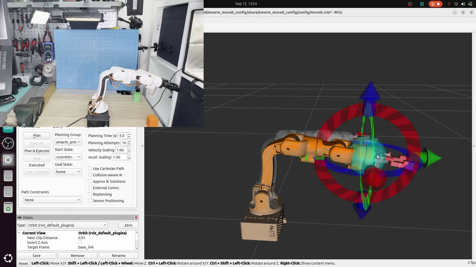
Two things are worth doing in simulation before touching the hardware. Plan a motion that would hit the table and watch the planner refuse or route around it. That is the collision layer proving it is on. And plan the same motion at default_velocity_scaling_factor 0.25 and 0.75, and watch the difference: same path, different clock.
14. Talking to the real hardware
A servo is not a joint. It has no encoder you can read, no notion of a trajectory, and no opinion about where it is. It takes a pulse width and holds whatever angle that pulse means, as fast as it can get there. Everything between a MoveIt trajectory and that pulse has to be built.
On the OmArm One that “everything” is three pieces: firmware on the ESP32, a wire protocol, and a ros2_control hardware plugin on the PC.
The firmware side
The arm’s six DS3240-180 servos hang on a PCA9685 over I²C, on channels {0, 3, 4, 7, 8, 11}. The SG90 gripper does not: it sits on GPIO 13 driven by the ESP32’s own LEDC peripheral at 50 Hz. The arm channels run at PWM_FREQ_HZ = 250, which the DS3240 accepts and which buys resolution: the finer the PWM period is divided, the finer the angle steps.
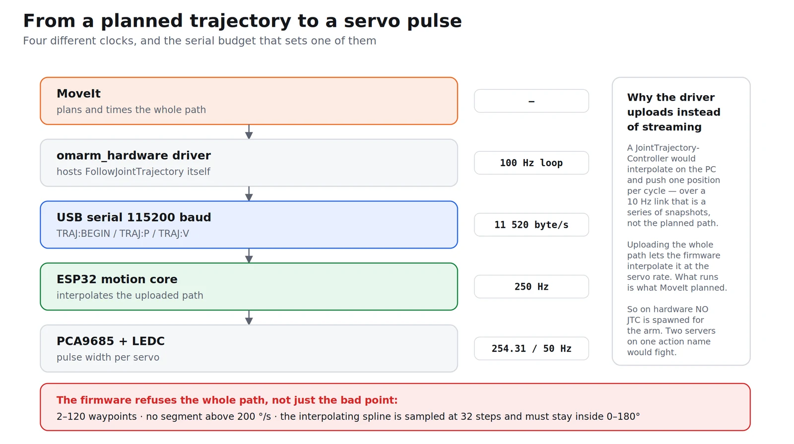
The firmware does not just forward pulses. xTaskCreatePinnedToCore(servoTask, "servo", 4096, nullptr, 3, &servoTaskHandle, 1) puts a motion core on its own task under FreeRTOS, the small real-time scheduler the ESP32 runs, pinned to core 1, woken by vTaskDelayUntil every SERVO_TICK_MS: 1000/250, so 4 ms, so 250 Hz. Serial parsing happens on the other core and cannot stall it. That core is what enforces the arm’s safety envelope. Three constants from motion.h define it:
| Constant | Value | What it bounds |
|---|---|---|
MOTION_MAX_TRAJ_POINTS |
120 | the longest trajectory it will accept |
MOTION_TRAJ_VMAX_HARD |
200 °/s | the fastest segment it will accept |
MOTION_TRAJ_VPEAK_MAX |
300 °/s | the fastest the interpolating spline may peak |
A trajectory that breaks any of those is refused as a whole, before a single servo moves. The firmware says why, in plain words: TRAJ count must be 2..120, TRAJ timestamps must increase, TRAJ angle outside 0-180, TRAJ segment exceeds the hardware speed limit, TRAJ spline would leave 0-180 between waypoints.
That last one is the interesting one. The firmware does not merely check the waypoints you sent; it samples the spline between them (MOTION_TRAJ_CHECK_STEPS = 32) and refuses if the interpolated curve would swing outside the servo’s range even though every waypoint is inside it. A trajectory can be legal at every point you specified and illegal in between.
The wire protocol
One USB cable, 115200 baud, line-based text in and JSON out. The commands, read out of the firmware’s parser:
| Command | Meaning |
|---|---|
STATUS |
full state as JSON |
SETPOS:<7 angles> |
tell the firmware where the arm physically is |
MOVE:<7 angles> |
go to these angles at the current speed limits |
LIMITS:<vmax>,<amax> |
set the speed envelope for the session |
STREAM:ON,<hz> / STREAM:OFF |
turn the state stream on at 1–100 Hz |
TRAJ:BEGIN,<n> |
start uploading a trajectory of n points (2–120) |
TRAJ:P,<idx>,<t_ms>,<7 angles> |
one waypoint |
TRAJ:V,<idx>,<7 velocities> |
the velocities at that waypoint |
ESTOP |
stop now |
HOME / ZERO |
go to the stored home |
SETPOS is the one that looks strange and matters most. The firmware refuses to move at all until it has been told where the arm is, because a servo cannot be asked. Power the board up and it does not know whether the arm is folded or extended; commanding anything would be a jump from an unknown pose to a known one at full speed. So the driver has to say “the arm is here” before anything else works.
The driver side
omarm_hardware/OmArmSystem is the ros2_control plugin. It implements the lifecycle (on_init, on_configure, on_activate, on_deactivate) plus read() and write(), and it does two things beyond the minimum.
It converts, per joint, on the PC. The conversion from a URDF angle to a servo angle is one line:
const double deg = c.offset_deg + c.scale * rad * 180.0 / M_PI;
const double clamped = std::min(c.max_deg, std::max(c.min_deg, deg));
Four numbers per joint: offset_deg (servo degrees at 0 rad), scale (servo degrees per URDF degree; −1 mirrors the joint), and a min_deg/max_deg clamp. They are read from <param> tags on the joint, which means recalibrating an arm never requires reflashing the ESP32. The firmware only ever speaks servo degrees.
Worth noting what the shipped configuration does with that mechanism: nothing. No joint overrides the defaults: offset 0, scale 1, clamp 0…180. Every correction lives in the URDF geometry instead, where it is visible to the simulation too. A calibration that sits only in the driver is invisible to Gazebo, and then the model and the machine disagree again in exactly the way section 3 was about.
The clamp is deliberately noisy. A silent clamp is the worst failure mode a calibration offset can have: the arm quietly stops short of the commanded angle and every layer above still believes it arrived.
It serves FollowJointTrajectory itself. This is the one place where the real arm differs structurally from the simulation, and the reason is the firmware’s TRAJ interface. A JointTrajectoryController interpolates the path itself and writes one position per control cycle, which over a 10 Hz serial link would be a stream of snapshots, not the path MoveIt planned. The driver instead takes the whole trajectory, uploads it with TRAJ:BEGIN / TRAJ:P / TRAJ:V, and lets the firmware interpolate it at 250 Hz. What executes is the planned path, at the servo rate, not a serial-rate approximation of it. MoveIt cannot tell the two apart: same action name, same semantics.
Which is why, on the real robot, no JointTrajectoryController is spawned for the arm. Two servers on one action name would fight over the command interfaces. The gripper keeps its controller. It is one joint, and streaming position commands to it is fine.
The serial budget
115 200 baud is 11 520 bytes per second, and that number decides the defaults. The driver’s send_rate_hz is 10 and stream_rate_hz is 20, not because those are round numbers but because a command reply and a state line have measurable sizes and they have to fit.
The trap here is thinking of the rate as free. Every command the driver sends is answered, so raising the send rate to get a snappier gripper raises the reply traffic in lockstep. Past a certain point the link is the bottleneck and commands wait behind replies, which is the opposite of what was wanted. The fix is a smaller reply, not a higher rate, which is why trajectory uploads are acknowledged with a short {"ok":1} rather than a full status line.
Starting from where the arm actually is
The last piece is what happens at activation, and it is the difference between a stack that starts safely and one that throws the arm across the bench.
The naive version puts a hardcoded start pose in the URDF and commands it. The arm is wherever it was left; the controller commands home; the first write is a full-speed jump. The driver instead asks the firmware for the arm’s real position while activating and adopts it into both the state and the command, so every controller starts from where the arm already is and the first commanded motion is zero.
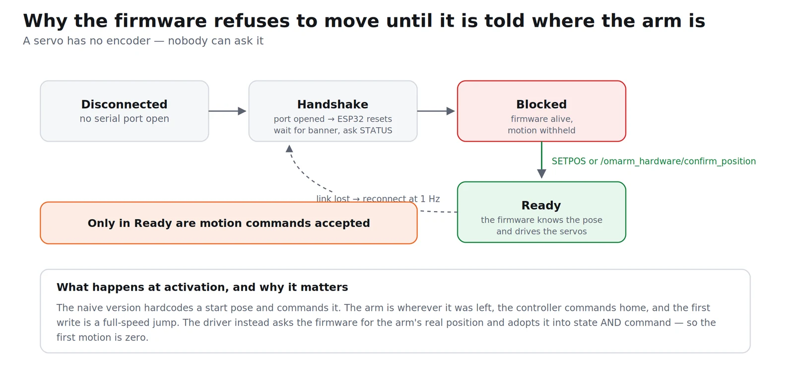
The initial_value entries in omarm.ros2control are therefore the simulation’s start pose. On hardware they are a placeholder that gets overwritten before anything moves.
15. Driving the real arm from MoveIt
Plug the ESP32 in. The driver finds the port by USB vendor and product id across /dev/ttyUSB* and /dev/ttyACM*, so no udev rule is needed.
The stack is started by a script rather than by hand:
bash tools/restart_hardware.sh
It stops anything already running, waits, and relaunches. The two details in it are worth copying into your own projects.
It sends SIGTERM first, not SIGKILL. That lets the driver run on_deactivate, which sends ESTOP and STREAM:OFF so the board is not left talking into a closed port. Only processes that are still alive six seconds later get SIGKILL.
And the kill patterns live inside the script, not on your command line. Typing pkill -f "ros2 launch omarm_moveit_config demo_hardware" into a shell makes pkill match the very command line that contains the pattern, so the shell kills itself before it reaches the launch. That one has cost everybody an afternoon at least once.
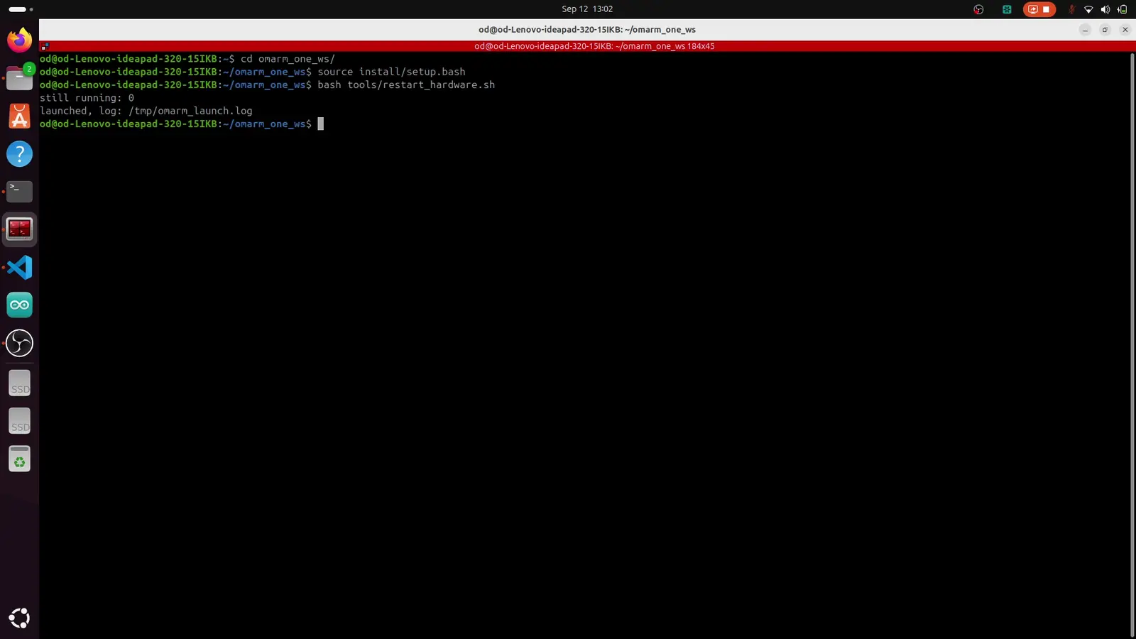
What it launches is demo_hardware.launch.py: robot_state_publisher, ros2_control_node (the controller manager), spawners for joint_state_broadcaster and omarm_gripper_controller, move_group, and RViz.
Then the workflow is identical to section 13. Drag the marker, Plan, Execute — and this time the arm moves.
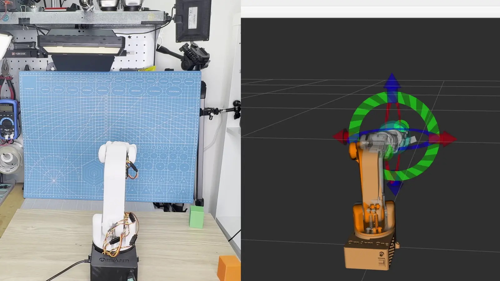
A first-session checklist:
- Start at
default_velocity_scaling_factor: 0.25and raise it once the arm has proved it tracks. - Keep the servo power switch from Part 1 within reach of your free hand.
- Plan first, look at the ghost, and only then execute. The preview is free.
- Watch the log for clamp warnings. A clamped joint means a calibration or limit is wrong, not that the clamp needs widening.
16. Troubleshooting
| Symptom | Cause / fix |
|---|---|
| The model in RViz never moves, even though the arm does | joint_state_broadcaster is not active. ros2 control list_controllers lists every loaded controller with its status. |
| The arm sags the moment it spawns in Gazebo | No controllers loaded yet. Spawning puts the model in the world; nothing holds the joints until a controller is active. |
| A joint moves the opposite way to the model | The <axis> sign for that joint. Section 3 — four of six were wrong in the export. |
| Everything is mirrored and offset | Axis sign plus zero pose. Fix the sign first, then the offset; doing both at once makes it impossible to tell which change did what. |
| MoveIt plans, then execution fails immediately | The controller named in moveit_controllers.yaml is not the one that is actually running. The names in both YAML files have to match exactly. |
| The interactive marker is drawn near the base, not the gripper | The end-effector group has no links listed. Section 12. |
| The firmware refuses a trajectory that looks fine | The spline between your waypoints leaves the 0–180° range even though every waypoint is inside it. Add an intermediate waypoint. |
| Trajectories are refused as too fast | A single segment exceeds 200 °/s. That is a firmware limit and it rejects the whole path. Lower default_velocity_scaling_factor. |
| The arm jumps at startup | The driver is not adopting the firmware’s position, or the firmware never got SETPOS. Nothing should move until the arm’s real pose is known. |
| The gripper is slow and gets slower at higher send rates | The serial link is saturated by reply traffic. Section 14. |
pkill kills your own terminal |
The pattern matched your own command line. Put it in a script. |
17. FAQ
Do I have to redo the URDF audit for my own arm?
Yes, and it is the part you cannot copy. The lengths in a CAD export are right for whoever’s CAD it was; the axis signs and zero poses depend on how your servos were bolted on. The method transfers; the numbers do not.
Can I skip ros2_control and command servos directly?
You can, and Part 1 did exactly that. What you lose is every layer above it: MoveIt will not talk to you, there is no /joint_states for RViz, and simulation and hardware stop being interchangeable.
Why does the arm need a world link?
So that something in the model is fixed. Without it Gazebo treats the base as free, and MoveIt has no immovable reference for planning.
Is the closed-form IK in the package?
No. The derivation in section 8 was done to verify the model and to understand what the solver does; MoveIt uses KDL on the exact geometry. If you want an analytic solver in production, generate one with IKFast rather than writing it by hand.
Why is the gripper’s second gear a mimic joint instead of a controlled one?
Because it is coupled mechanically. Two command interfaces on one gear pair means two controllers fighting over the same physical thing.
Can I run this on Windows?
Through WSL 2, the same way as Part 2 — with one caveat: passing a USB serial device into WSL 2 needs extra setup, so the hardware half of this part is easier on a native Linux machine.
How accurate is the arm?
The model is accurate to a millimetre or so, which section 8 quantifies. How closely the physical arm follows the model is a separate question and a measurement, not a calculation. Plastic gears, servo deadband and a printed structure all sit between the two.
18. What comes next
The OmArm One now takes a pose instead of six angles. MoveIt plans around its own body, times the path against real limits, and the same trajectory runs in Gazebo and on the bench without changing a line.
What it still cannot do is decide where to reach. Every target in this part came from a human dragging a marker. Part 4 gives the arm a camera: calibrating it against the robot’s frame, finding an object in the image, and turning a pixel into a pose that this stack can already execute.
If you work through the audit on your own arm, I would like to see the before-and-after table. And if your exporter produces something this post does not cover, tell me which one. The list in section 2 grows with every report.
Resources
- This post as a video, 8 minutes: (link once published)
- The complete ROS 2 workspace, firmware and tools: Part 3 download
- The arm itself — CAD, firmware, BOM: github.com/OmArTronics/OmArm-One
- Part 1: the build · Part 1.5: the game controller · Part 2: the digital twin