
This post contains affiliate links, marked with *. As an Amazon Associate I earn from qualifying purchases, at no extra cost to you. It helps keep the tutorials free.
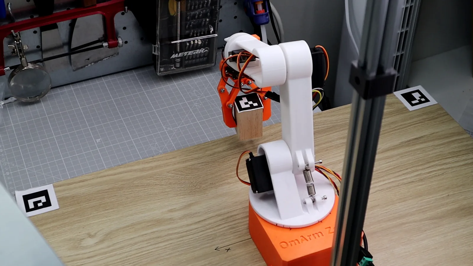
OmArm Zero Series
Part 1: Build · Part 2: URDF + RViz + Gazebo · Part 3: MoveIt 2 · Part 4: Computer Vision Pick-and-Place (this post)
The video loads from YouTube (Google), which may set cookies. Privacy policy
At a glance
What you’ll build: A vision-guided pick-and-place pipeline for the OmArm Zero, in Gazebo and on the real arm.
The OmArm Zero has five arm joints plus a gripper; Part 1 counts this as 6-DOF (5+1). Only the five arm joints position the gripper, so this post calls it a 5-DOF arm (DOF = degrees of freedom, here the number of independent joints).
Prerequisites: Parts 1 to 3 completed: assembled arm with the ROS 2 serial firmware, working URDF, MoveIt config and hardware bridge. You should be able to launch real_moveit.launch.py and move the real arm from RViz.
Hardware: Any USB webcam (720 p or higher) on a rigid overhead mount, about 0.5 m above the table and looking straight down. A printer for the ArUco markers. A small block (mine is 3 × 3 × 10 cm with a 31 mm marker glued on top; the code and this post call it “the cube”).
Software: Ubuntu 24.04, ROS 2 Jazzy, Gazebo Harmonic, MoveIt 2, OpenCV (with ArUco), NumPy, SciPy.
Time: A weekend, including both calibrations and real-robot tuning.
Difficulty: Advanced.
Get the package and run it
The code on this page shows the key excerpts. The complete source for Parts 2 to 4, with every ROS 2 package, launch file, calibration tool and parameter file, is in the OmArm Zero ROS 2 workspace package (29 €). The ESP32 firmware is free in the OmArm Zero GitHub repository; the ROS 2 workspace is only in the package.
Unpack the archive and build once:
cd omarm_zero_ws
source /opt/ros/jazzy/setup.bash
rosdep install --from-paths src --ignore-src -y   # pulls OpenCV, MoveIt, etc.
colcon build --symlink-install
source install/setup.bash
From there, the Part 4 pipeline is five commands, in this order:
# 1. Print the five ArUco markers (section 3)
ros2 run computer_vision_aruco generate_markers \
    --marker-ids 0,1,2,3,4 --size 600 --dictionary 4X4_50

# 2. Intrinsic calibration — once per camera (section 4)
ros2 launch computer_vision_aruco camera_calibration.launch.py \
    camera_id:=0 checkerboard_width:=9 checkerboard_height:=6 square_size:=0.025

# 3. Extrinsic calibration — after mounting the camera (section 5)
ros2 run computer_vision_aruco calibrate_extrinsics --ros-args \
    --params-file src/computer_vision_aruco/config/aruco_params.yaml \
    -p output_file:=src/computer_vision_aruco/config/camera_extrinsics.yaml

# 4. Pick-and-place in SIMULATION, perception real (section 10)
ros2 launch omarm_zero_moveit_config cube_gazebo.launch.py \
    camera_info_url:=/absolute/path/to/your_calibration.yaml run_demo:=true

# 5. REAL robot: MoveIt, bridge and vision; home the arm in RViz, then start the task (section 11)
ros2 launch omarm_zero_moveit_config cube_real.launch.py \
    transport:=serial camera_info_url:=/absolute/path/to/your_calibration.yaml
Before step 3, tape the four corner markers to your table. Enter their measured positions in table_markers_expected inside src/computer_vision_aruco/config/aruco_params.yaml (section 5).
1. From motion planning to perception
In Part 3, MoveIt planned collision-free trajectories, and the bridge sent the goal of each one to the real servos on the ESP32. You could move the arm to any reachable pose by dragging an interactive marker in RViz or by typing joint angles into a Python script. The targets were always numbers that you provided.
Part 4 adds a camera. The arm finds a marked cube on the table and picks it up; you no longer type in the target.
Here is the plan. A USB camera looks straight down at the table. It spots the cube by the printed marker on top. An ArUco detector identifies the marker and estimates its 6-DOF pose (position and orientation) relative to the camera. A calibration step converts that pose into the robot’s own coordinate frame. The result is a position in meters, published on a ROS 2 topic that the pick-and-place task subscribes to. A custom inverse kinematics (IK) solver computes the joint angles that bring the gripper to that position for a vertical grasp. The arm descends straight down, grasps the cube, lifts it and places it at a marked target. Then the arm goes home and waits for the next cycle.
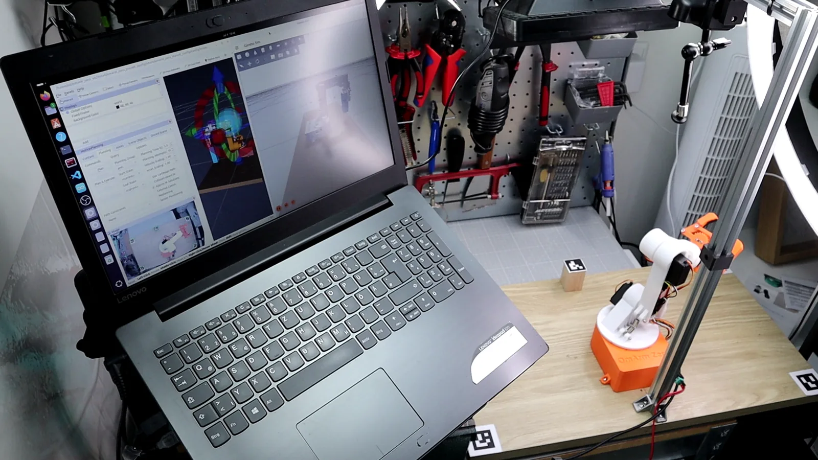
Markers instead of deep learning. A printed ArUco marker gives a full 6-DOF pose from one webcam. It needs no training data and no GPU; detection runs on the CPU. In my setup, the position error after calibration is about 1 cm (section 5). For a desktop arm that has to find one known object on a table, that is enough. You can swap the detector later, because the interface to the rest of the system is one ROS 2 topic, /cup_pose. The name is left over from a cup I planned to pick first; I switched to a cube and kept the topic name. Any detector that publishes a PoseStamped message (a ROS message with a position, an orientation, a timestamp and a frame name) on this topic will plug in.
Simulation first, with the real camera. The Gazebo scene mirrors the real table, and the cube in Gazebo spawns at the position the real camera reports for the real cube. You debug planning and grasping in simulation while the perception half is already the real thing. To switch to the real arm, you start cube_real.launch.py instead of cube_gazebo.launch.py. On the real arm, you start the task yourself after one home move in RViz, with the real-robot parameter file pick_place_params_real.yaml. Section 11 lists what differs on hardware.
2. The perception problem: from pixels to world coordinates
A camera measures pixels. The robot needs meters in its own base frame. Getting from one to the other is the core problem of robot vision, and it takes three ingredients.
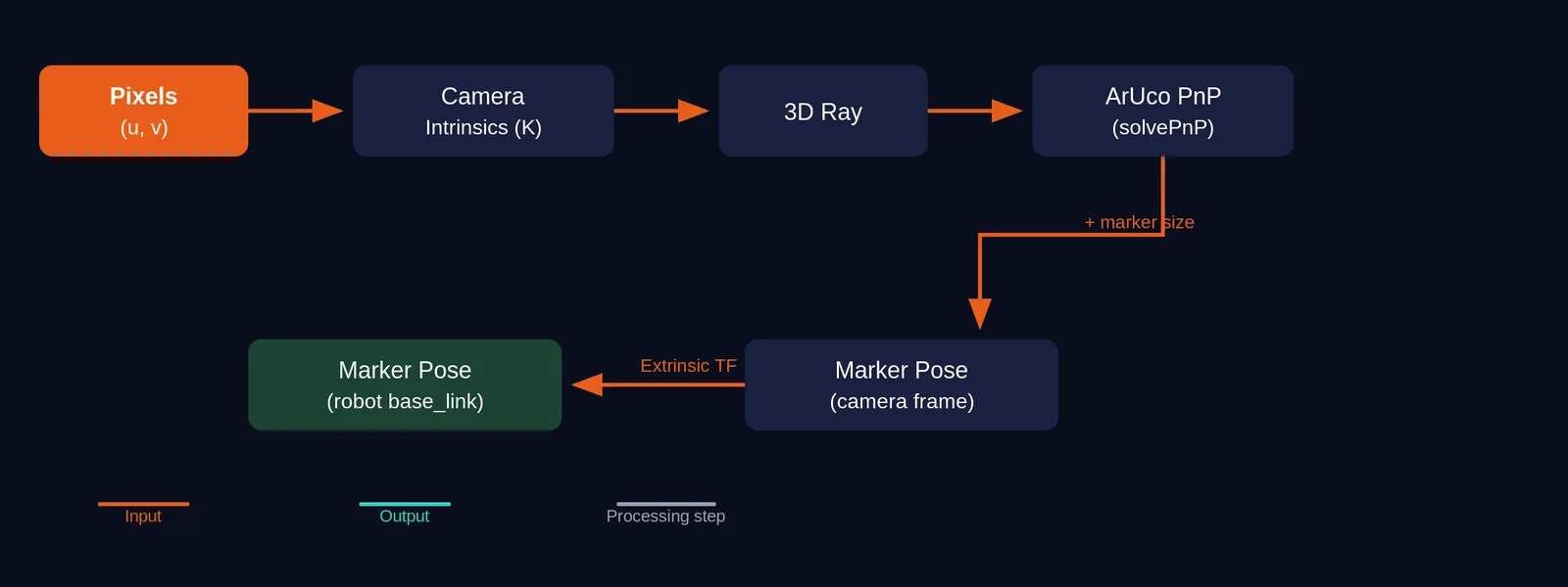
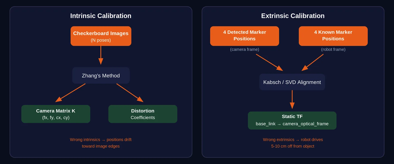
Intrinsics describe how your specific camera maps 3-D rays to 2-D pixels. The two focal lengths (fx, fy) tell you how many pixels one radian spans, horizontally and vertically. The optical center (cx, cy) tells you which pixel the camera’s central axis hits. The distortion coefficients describe how the lens bends the image, especially near the edges. Every camera unit is slightly different, even two copies of the same model, because of manufacturing tolerances in the lens and sensor placement. You have to measure these numbers for your camera. That process is called intrinsic calibration (section 4).
Marker geometry and PnP give you the marker’s pose relative to the camera. PnP stands for Perspective-n-Point. If you know the physical size of the marker (its side length in meters), and the camera has detected the four corners in pixels, you have four 3-D-to-2-D correspondences. That is enough to solve for the rotation and translation from the marker to the camera. OpenCV’s solvePnP does this when you pass in the intrinsics, the corner pixels and the marker size. The output is a rotation vector and a translation vector that together describe the marker’s full 6-DOF pose in the camera’s optical frame.
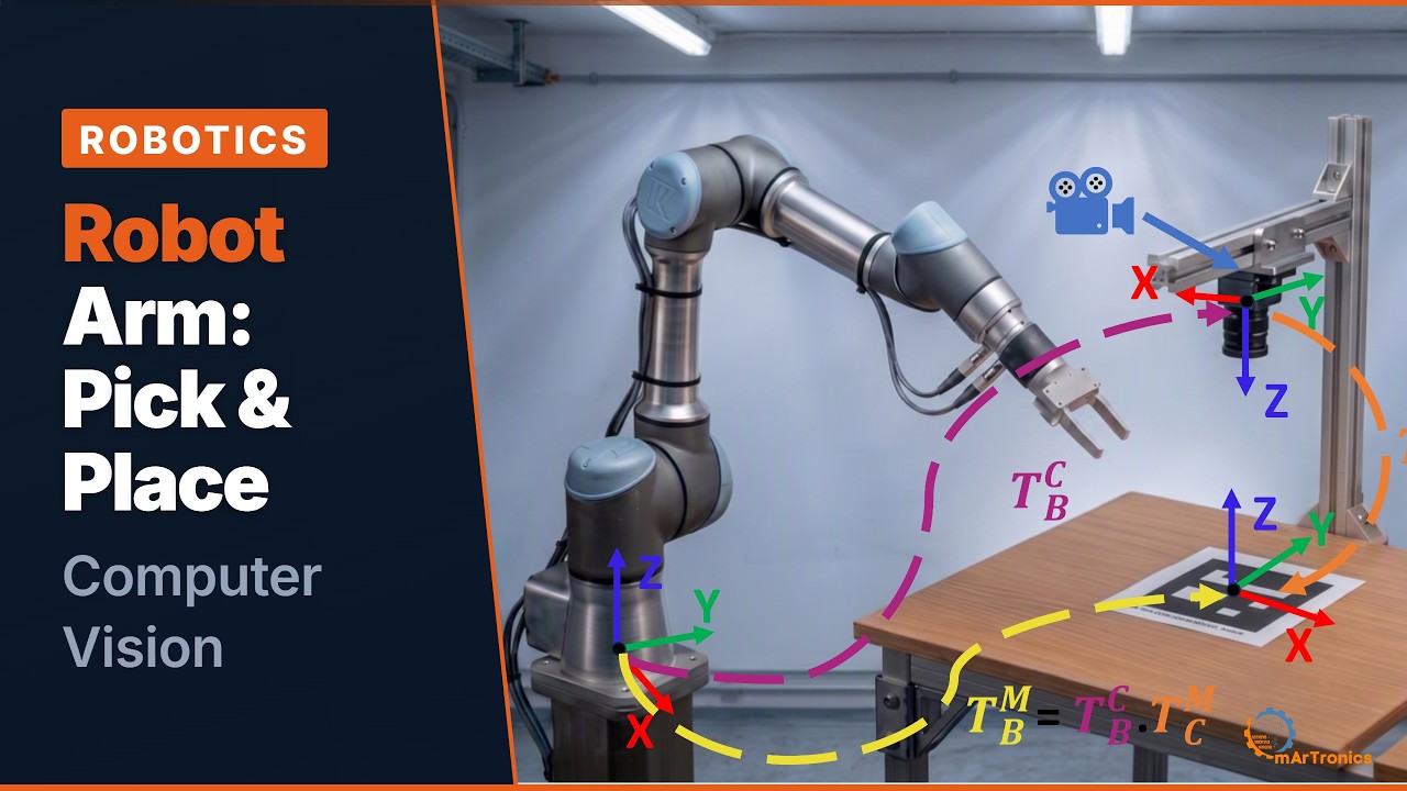
Extrinsics tell you where the camera sits relative to the robot. This is one fixed pose of camera_optical_frame relative to base_link. If you know where the camera is, and PnP tells you where the marker is relative to the camera, chaining the two gives you the marker relative to the robot. TF2 (TF for short), the ROS 2 library that tracks all coordinate frames and the poses between them, handles this chaining; you set it up in Part 2. The chain looks like this:
world == base_link --> camera_optical_frame --> aruco_marker_0 (the cube)
        (extrinsics, static)    (detector, live)
Each ingredient has its own failure mode. Wrong intrinsics bend the world so that positions drift toward the image edges. A wrong marker size scales everything (5 % error in the printed marker width means 5 % error in the estimated distance). Wrong extrinsics shift or rotate the whole scene. The classic symptom of bad extrinsics is the robot driving to a position that is consistently 5 to 10 cm away from the object.
3. ArUco markers: cheap 6-DOF poses
ArUco markers are binary square fiducials (printed reference markers that a camera can locate precisely). Each marker is a black square containing a grid of black and white cells that encode a unique integer ID. They were designed for camera-based pose estimation in robotics. OpenCV’s ArUco module detects their four corners at sub-pixel accuracy and identifies them by ID, so you can tell which marker is which when several are visible. With the physical side length it then solves PnP for a full 6-DOF pose.
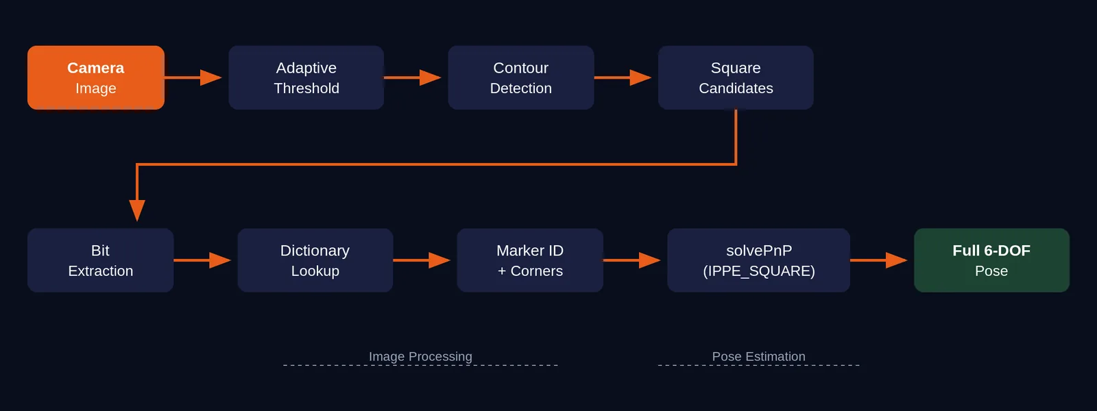
The detection pipeline works like this. The image is converted to grayscale. OpenCV runs adaptive thresholding to find all black square candidates. For each candidate, it checks whether the internal cell pattern matches a valid ID in the chosen dictionary. If it does, the four corner positions are refined to sub-pixel accuracy, and the marker ID is decoded. From those four corners plus the known physical size, solvePnP (using the SOLVEPNP_IPPE_SQUARE algorithm, which is optimized for square markers) computes the marker’s rotation and translation in the camera frame. Detection runs on the CPU, without a GPU.
I use the DICT_4X4_50 dictionary, which contains 50 markers with a 4×4 internal grid. A smaller grid means fewer bits per marker, so each cell is physically larger and easier to detect at longer distances or with lower resolution cameras. For a desktop setup with five markers, 50 is more than enough.
My marker inventory:
| ID | Location | Size | Purpose |
|---|---|---|---|
| 0 | On top of the cube | 31 mm | The object to pick |
| 1 | Table corner, front right (+X, -Y) | 31 mm | Extrinsic calibration rig |
| 2 | Table corner, back right (-X, -Y) | 31 mm | Extrinsic calibration rig |
| 3 | Table corner, back left (-X, +Y) | 31 mm | Extrinsic calibration rig |
| 4 | Table corner, front left (+X, +Y) | 31 mm | Extrinsic calibration rig / place target |
Front, back, left and right are seen from the robot: +X points forward, +Y points to the robot’s left.
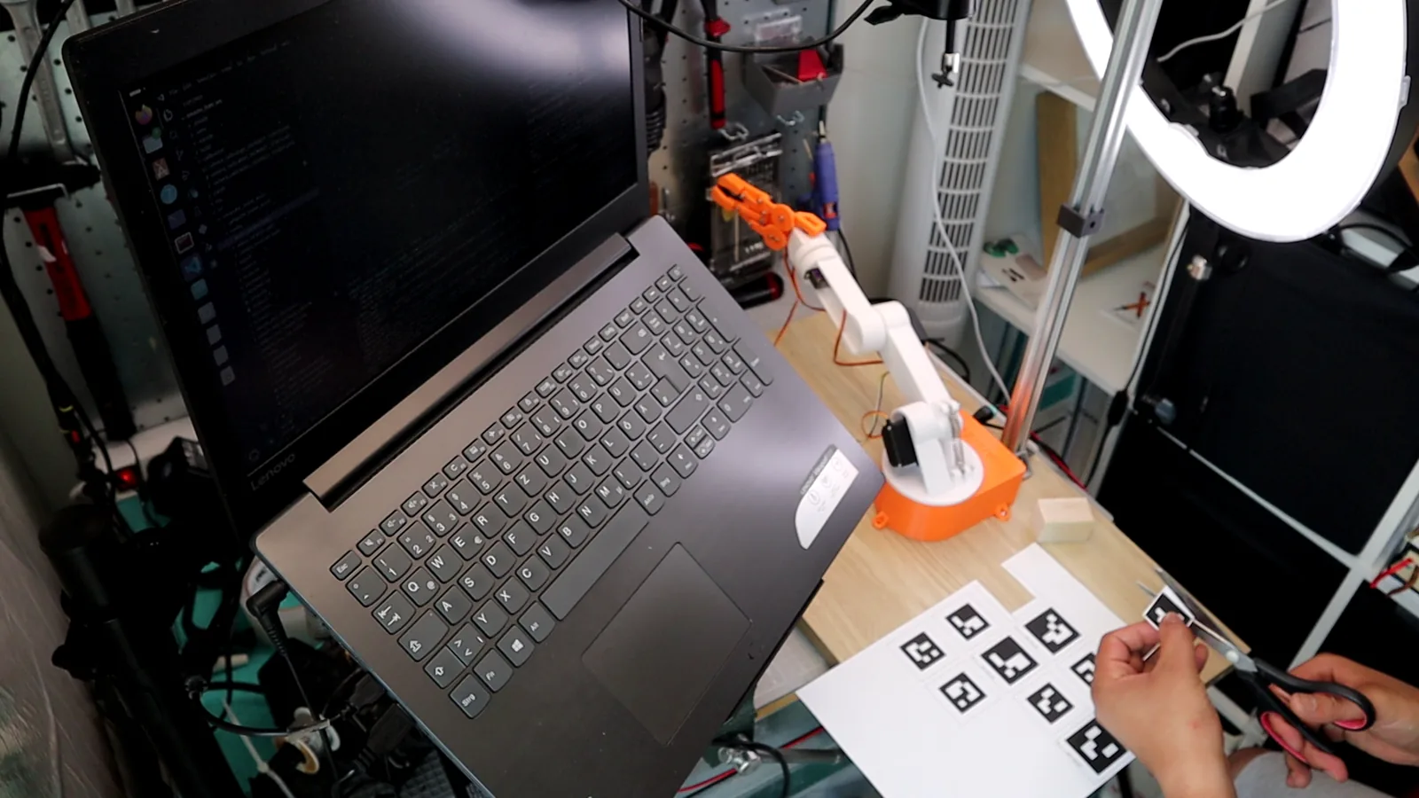
Generate and print them with:
ros2 run computer_vision_aruco generate_markers \
    --marker-ids 0,1,2,3,4 --size 600 --dictionary 4X4_50
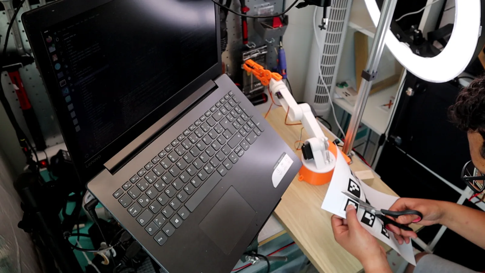
Printing tips:
Measure the printed black square with calipers and use that value in the config, not the value you asked the printer for. Printers scale. If your printer shrinks the marker by 5 %, every distance estimate from that marker will be off by 5 %. I set all five markers to 31 mm (marker_size: 0.031 in the config), but your printer might produce 30 mm or 32 mm. On my cube, the printed marker with its white border is wider than the 3 × 3 cm top and overhangs the edges (photos in section 11).
Use matte paper. Glossy paper under ceiling lights creates reflections that wipe out the black cells. The detector sees a white blob instead of a marker and drops the detection. Matte inkjet paper is fine.
Keep a white border (the “quiet zone”) around the black square. The detector needs contrast between the marker edge and its surroundings to find the square outline.
Check your resolution. A 31 mm marker at 0.5 m distance covers roughly 45 pixels at 1280×720. That works, but it is the lower limit for reliable detection. At 640×480, the marker shrinks to about 23 pixels and detection becomes unreliable. Use 720 p or higher, and add more light.
4. Camera setup and intrinsic calibration
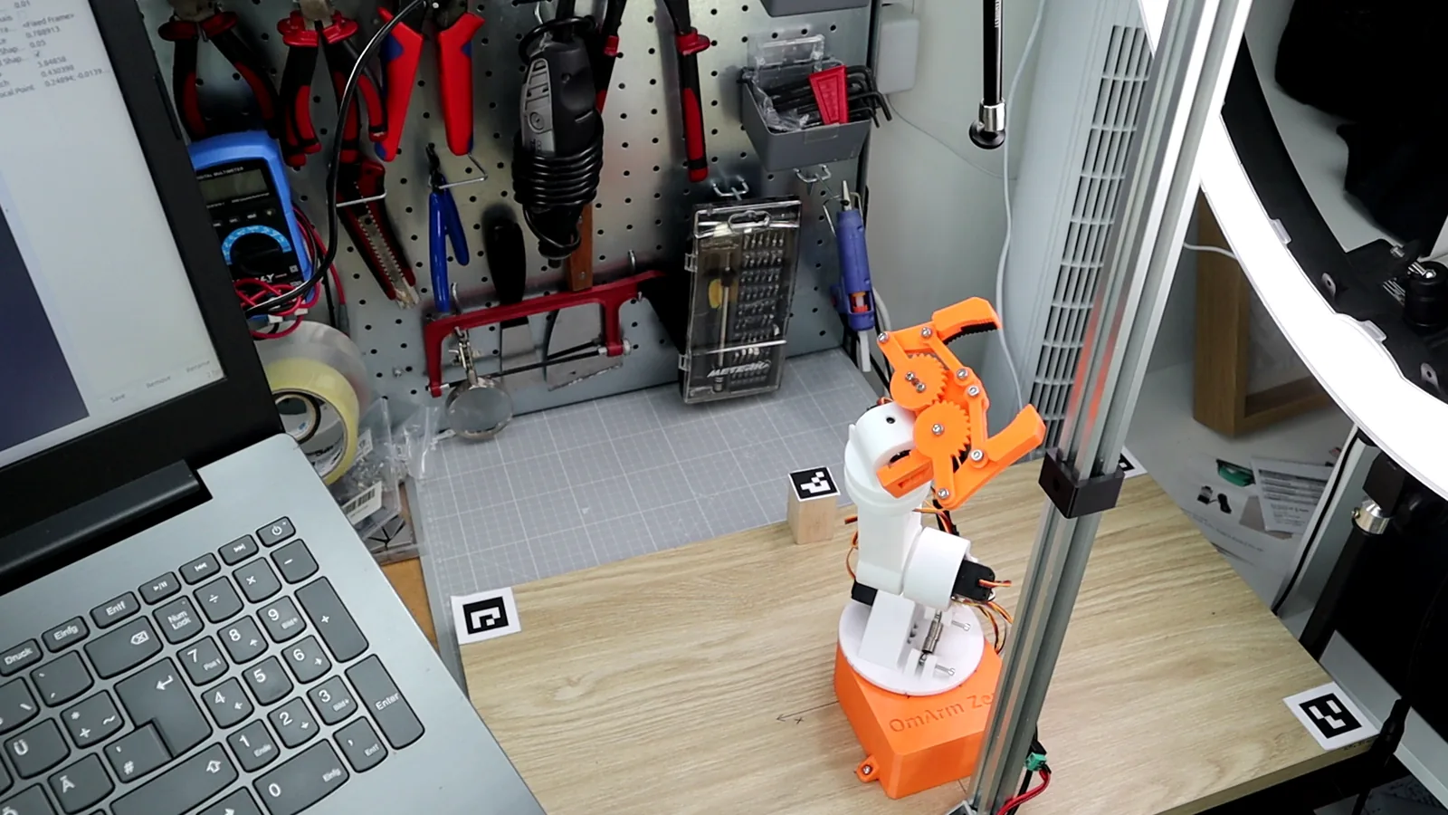
Mount the webcam rigidly, looking straight down, roughly centered over the workspace, at about 0.5 m height. Every millimeter the camera moves after calibration is a millimeter of grasp error. I used a small aluminum photo stand clamped to the desk, with the camera zip-tied to the crossbar. Anything that does not wobble when you touch the table will work.
What intrinsic calibration does
When you point a camera at a straight line in the real world, the line appears slightly curved in the image, especially near the edges. That is lens distortion. Every lens has it. The pinhole camera model assumes light rays travel in straight lines through a single point, but real lenses are pieces of curved glass, and they bend the rays.
Intrinsic calibration measures how your lens bends those rays. The output is a set of numbers: the focal lengths (fx and fy), the optical center (cx and cy), and five distortion coefficients. With these numbers, OpenCV can “undistort” the image so that straight lines in the world look straight in the image again. PnP also needs these numbers to compute accurate 3-D poses from 2-D pixel positions.
The calibration procedure
You calibrate with a printed checkerboard pattern. The board has a known grid of alternating black and white squares. OpenCV detects the inner corners of the grid (where four squares meet) and uses them as calibration points. By seeing the same board at many angles and positions across the image, the algorithm (Zhang’s method) solves for all intrinsic parameters at once.
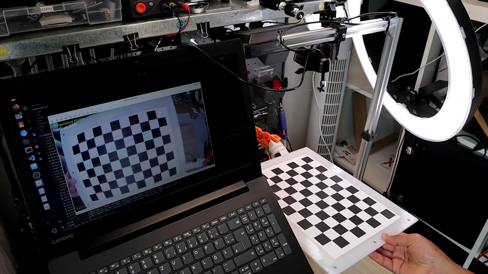
Print a checkerboard (9 columns by 6 rows of inner corners is standard) and glue it to something flat and rigid, for example a piece of cardboard. Then run:
ros2 launch computer_vision_aruco camera_calibration.launch.py \
    camera_id:=0 checkerboard_width:=9 checkerboard_height:=6 square_size:=0.025
square_size is the side length of one printed checkerboard square in meters (25 mm here). Measure your print and enter that value.
The calibration window opens and shows the live camera feed. Hold the checkerboard in front of the camera and tilt it in different orientations. Press SPACE to capture each pose. Collect at least 20 poses. Cover the whole field of view, especially the corners and edges, because that is where distortion is worst. My calibration at 1280×720 ended with an RMS (root mean square) reprojection error of 0.21 pixels. On average, the corners predicted by the fitted camera model sit 0.21 pixels from the corners OpenCV detected.
Two rules:
Calibrate at the resolution you will run at. Intrinsic parameters are specific to the image resolution. If you calibrate at 1920×1080 and then run the detector at 1280×720, the focal lengths will be wrong and your poses will drift. My config runs at 1280×720 (frame_width: 1280, frame_height: 720), so I calibrate at 1280×720.
Cover the whole field of view with board poses. If all your captures are in the center of the image, the algorithm has no data to estimate the distortion at the edges. Sooner or later the cube sits near an image edge, and poor distortion correction there means poor pose estimates there.
Press c to run the calibration and s to save. The result is a YAML file in ./calibration/camera_calibration_<timestamp>.yaml. This file becomes your camera_info_url for all later launches.
Verify that the camera node loaded your calibration:
ros2 topic echo /camera/camera_info --once
The output must show your focal lengths, not zeros or defaults. If it shows a 3×3 identity matrix as the camera matrix, the calibration file was not loaded. Check the path.
5. Extrinsic calibration: the four-marker table rig
My first attempt at the extrinsics failed.
I measured the camera pose by hand. It was about 50 cm up, roughly centered, pointing straight down. I typed the camera’s three rotation angles into a static TF publisher (a node that broadcasts one fixed pose between two frames) and launched the pipeline. The result: the detected cube position was wrong, and the arm drove to a spot 10 cm away from the cube on every run. The error was consistent, which is the hallmark of a calibration problem rather than random noise.
Why measuring the camera angle by eye fails: one degree of camera tilt at 0.5 m height produces about 9 mm of position error at the table surface. You cannot see one degree of tilt. The camera’s optical axis is invisible, so even the tilt direction is guesswork. The translation (XY offset of the camera from the robot base) is easier to measure with a ruler, but the rotation is not.
The fix: calibrate against four measured table markers
The four table-corner markers have known positions in the robot frame. You measure each marker’s center distance from the robot base with a ruler. These go into aruco_params.yaml as the table_markers_expected parameter:
table_markers_expected: '{"1":[0.272,-0.1645],"2":[-0.272,-0.1645],
                          "3":[-0.272,0.1345],"4":[0.272,0.1345]}'
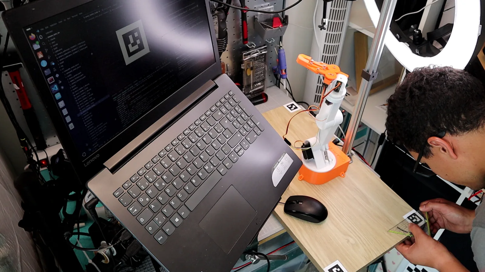
Each entry is the marker center’s XY position in the robot’s base_link frame, in meters. Positive X is in front of the robot, positive Y is to the left. The Z coordinate is zero because the markers lie flat on the table, and base_link sits on the table surface.
The camera sees those same markers in its own optical frame. So now you have four 3-D point correspondences: four points whose positions you know in both the camera frame and the robot frame. Finding the rotation and translation that map one set of points onto the other is the Kabsch algorithm, also known as the orthogonal Procrustes problem.
How Kabsch/SVD works (for beginners)
You have two sets of points: P_cam (marker positions in the camera frame, averaged over about 200 frames to reduce noise) and P_base (the positions you measured with a ruler). You want the rotation R and translation t such that P_base = R * P_cam + t, minimizing the sum of squared distances between predicted and measured positions.
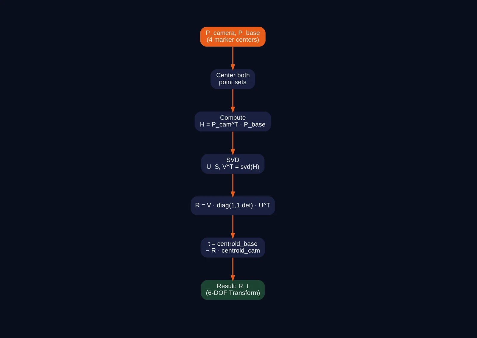
The algorithm works in three steps. First, center both point sets by subtracting their means. Second, compute the cross-covariance matrix H between the centered point sets (a 3 × 3 matrix that sums how the coordinates of matching points vary together). Then take its Singular Value Decomposition (SVD), a standard factorization of H into two orthogonal matrices (rotations, possibly combined with a reflection) and a diagonal matrix of scaling factors. Third, construct the rotation from the SVD factors, with a sign correction to ensure a proper rotation (not a reflection). The translation follows from the centroids and the rotation.
The implementation from calibrate_extrinsics.py:
@staticmethod
def _kabsch(P_src, P_dst):
    """Rigid transform mapping P_src -> P_dst: dst = R @ src + t."""
    c_s = P_src.mean(axis=0)
    c_d = P_dst.mean(axis=0)
    H = (P_src - c_s).T @ (P_dst - c_d)
    U, _, Vt = np.linalg.svd(H)
    d = np.sign(np.linalg.det(Vt.T @ U.T))
    D = np.diag([1.0, 1.0, d])
    R = Vt.T @ D @ U.T
    t = c_d - R @ c_s
    return R, t
The D = np.diag([1.0, 1.0, d]) line is the reflection correction. If det(V * U^T) is negative, the SVD found a reflection instead of a rotation. Flipping the sign of the third column fixes it. Without this correction, the result would mirror the scene, and the arm would reach for positions on the wrong side.
Running the calibration
Check that the camera is mounted, all four table markers are visible, and the ArUco detector is running. Then:
ros2 run computer_vision_aruco calibrate_extrinsics --ros-args \
    --params-file src/computer_vision_aruco/config/aruco_params.yaml \
    -p output_file:=src/computer_vision_aruco/config/camera_extrinsics.yaml
The node collects 200 TF samples per marker (the samples: 200 parameter in aruco_params.yaml), averages them to reduce jitter, runs the Kabsch solve, and writes the result to camera_extrinsics.yaml. It reports the residual RMS (the typical error across all markers). This value tells you how well the computed camera pose reproduces the known marker positions:
Marker 1: Residuum 0.78 cm
Marker 2: Residuum 1.12 cm
Marker 3: Residuum 0.85 cm
Marker 4: Residuum 1.03 cm
RMS = 0.95 cm   (Marker: 1,2,3,4)
The RMS residual is 0.95 cm; the worst marker (ID 2) is off by 1.12 cm. For a cube 3 cm wide, that is enough for a reliable grasp.
The calibration also sanity-checks the result. If the camera Z is negative (the camera would be below the table), if the optical axis does not point downward, or if the RMS exceeds 2 cm, it logs a warning. These checks catch sign errors in the measured marker positions, which are the most common mistake.
Continuous verification
After calibration, the cube_pose_publisher node keeps checking the four table markers against their expected positions and logs the RMS every two seconds. This block is copied from my terminal (screenshot in section 10):
Table-marker verification (base_link X/Y):
  ID 1: detected (+0.278,-0.163) expected (+0.272,-0.165) err=0.6 cm
  ID 2: detected (-0.279,-0.161) expected (-0.272,-0.165) err=0.7 cm
  ID 3: detected (-0.280,+0.128) expected (-0.272,+0.135) err=1.0 cm
  ID 4: detected (+0.280,+0.127) expected (+0.272,+0.135) err=1.1 cm
  RMS error = 0.9 cm
If someone bumps the camera stand, the RMS jumps at once. One rule: the corner markers are your reference rig. Never move them, and never print a second copy of a corner marker (section 9).
6. The vision pipeline: three nodes, one launch
The vision system consists of three ROS 2 nodes that run together in a single launch file. Each node has one job, and they communicate through the standard ROS 2 mechanisms: topics for data, TF for poses between frames.
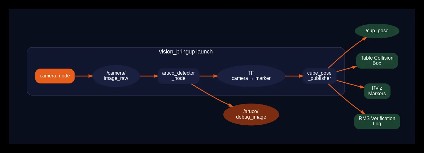
camera_node --image--> aruco_detector_node --TF--> cube_pose_publisher --> /cup_pose
                              |                            |
                       /aruco/debug_image        table collision object,
                                                 RViz markers, RMS log
Launch the whole vision pipeline with:
ros2 launch computer_vision_aruco vision_bringup.launch.py \
    camera_info_url:=/absolute/path/to/your_calibration.yaml
Node 1: camera_node
The camera node opens the USB webcam and captures frames at 30 fps. It publishes them as ROS 2 Image messages along with CameraInfo messages (which contain the intrinsic calibration). The config in aruco_params.yaml specifies the camera device:
camera_node:
  ros__parameters:
    camera_device: "/dev/v4l/by-id/usb-HD_Web_Camera_HD_Web_Camera_Ucamera001-video-index0"
    camera_id: 0                     # fallback only
    frame_rate: 30.0
    frame_width: 1280
    frame_height: 720
    camera_frame: "camera_optical_frame"
    camera_info_url: ""              # path to calibrated intrinsics (override at launch)
A practical tip: use the camera_device path (the /dev/v4l/by-id/… symlink) instead of camera_id. Laptops have built-in webcams that also claim video indices, and the indices can swap every time you replug the USB camera. The by-id path is stable because it is based on the camera’s USB descriptor, not its enumeration order. On my laptop, the built-in webcam and the USB camera swapped between video0 and video2 after a replug or reboot, so my config uses the by-id path.
Node 2: aruco_detector_node
This node subscribes to the camera images, detects ArUco markers, estimates their poses, and broadcasts TF frames. The setup from the source code:
class ArucoDetectorNode(Node):
    def __init__(self):
        super().__init__('aruco_detector_node')

        self.declare_parameter('marker_size', 0.05)
        self.declare_parameter('marker_sizes', '')       # per-ID JSON
        self.declare_parameter('dictionary', '4X4_50')
        self.declare_parameter('camera_frame', 'camera_link')
        self.declare_parameter('publish_tf', True)
        self.declare_parameter('tf_prefix', 'aruco_marker_')

        # ... parameter loading ...

        # Initialize ArUco detector (compatible with OpenCV 4.7+)
        self.aruco_dict = self.get_aruco_dictionary(self.dictionary_name)
        self.aruco_params = self.get_detector_parameters()
        cv_version = tuple(map(int, cv2.__version__.split('.')[:2]))
        if cv_version >= (4, 7):
            self.aruco_detector = cv2.aruco.ArucoDetector(
                self.aruco_dict, self.aruco_params)
            self.use_new_api = True
The config supports per-ID marker sizes as a JSON string, so you can use different physical sizes for different markers. In my setup, all five markers are 31 mm:
aruco_detector_node:
  ros__parameters:
    marker_size: 0.031
    marker_sizes: '{"0": 0.031, "1": 0.031, "2": 0.031, "3": 0.031, "4": 0.031}'
    dictionary: "4X4_50"
    camera_frame: "camera_optical_frame"
    publish_tf: true
    tf_prefix: "aruco_marker_"
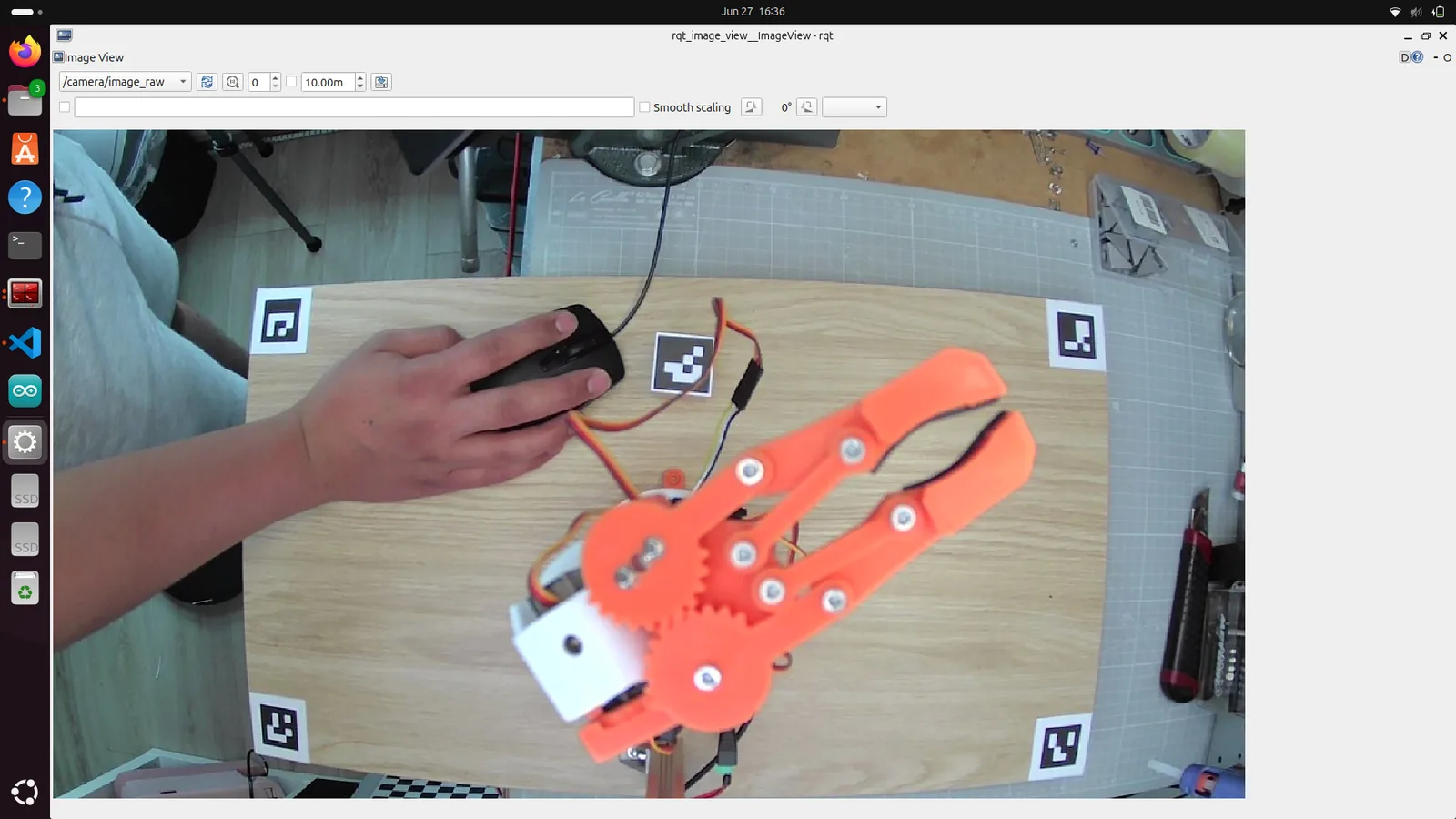
For each detected marker, the node broadcasts a TF frame aruco_marker_<id> relative to camera_optical_frame. It also publishes a debug image on /aruco/debug_image that shows the detected markers with their bounding boxes and IDs drawn on top. Open this in rqt_image_view (a small ROS tool that displays an image topic) to verify that detection works.
Node 3: cube_pose_publisher
This node turns raw detections into something the pick-and-place task can use. A raw TF lookup gives you the marker position, but that position jitters from frame to frame and can have single-frame outliers. It also does not tell you whether the marker is still visible or the data is stale. The cube pose publisher adds four functions on top of the raw detection.
EWMA smoothing. A 31 mm marker at 0.5 m distance jitters a few millimeters from frame to frame because of image noise, corner detection uncertainty and slight camera vibration. An Exponentially Weighted Moving Average (EWMA) filter steadies the position. EWMA is a filter where each new position is blended with the previous smoothed position using a weight alpha:
smoothed = alpha * new + (1 - alpha) * smoothed_previous
With smoothing_alpha: 0.3, each new detection contributes 30 % and the history contributes 70 %. This produces a smooth position that responds to real movement within a few frames but filters out single-frame noise. The filtering logic from the source:
if self.smoothed is not None and self._reject_count < 5:
    jump = math.dist((x, y, z), self.smoothed)
    if jump > self.min_jump:
        self._reject_count += 1
        self.get_logger().warn(
            f'Cube pose jump {jump*100:.1f} cm > '
            f'{self.min_jump*100:.1f} cm — ignoring outlier '
            f'({self._reject_count}/5)')
    else:
        self._reject_count = 0
        x = self.alpha * x + (1 - self.alpha) * self.smoothed[0]
        y = self.alpha * y + (1 - self.alpha) * self.smoothed[1]
        z = self.alpha * z + (1 - self.alpha) * self.smoothed[2]
        self.smoothed = (x, y, z)
Outlier rejection with self-recovery. If a new detection jumps more than min_position_jump (5 cm by default) from the smoothed position, it is rejected as an outlier. This handles single-frame detection glitches where the marker corner localization goes wrong. If the cube was moved to a new position, consecutive “outliers” will agree with each other. After 5 consecutive rejections, the filter assumes the cube did move and re-seeds to the new position.
Freshness. The /cup_pose topic is only published while the marker is seen and the TF data is fresh (less than pose_timeout_sec seconds old). If the cube is out of view or the marker is occluded, /cup_pose stops updating. The pick task checks for this and never acts on a stale pose.
Table collision object. The publisher also adds a box collision object representing the table to the MoveIt planning scene. This prevents MoveIt from planning trajectories that drive the arm through the table surface. The table dimensions and position come from the config:
cube_pose_publisher_node:
  ros__parameters:
    marker_frame: "aruco_marker_0"
    target_frame: "world"
    cube_size_x: 0.03
    cube_size_y: 0.03
    cube_size_z: 0.10
    cube_center_z: 0.05
    publish_rate: 10.0
    pose_timeout_sec: 3.0
    smoothing_alpha: 0.3
    min_position_jump: 0.05
    enable_planning_scene: false     # cube collision OFF (blocks grasp plans)
    enable_table: true
    table_size_x: 0.60
    table_size_y: 0.35
    table_size_z: 0.02
Note enable_planning_scene: false for the cube itself. I tried adding the cube as a collision object, but it blocked the grasp plan. When the fingers need to wrap around the cube, a collision object at the cube position prevents MoveIt from planning the approach. Instead, the cube is shown as a blue RViz marker (visual only, no collision), and the table stays as a collision object to protect the arm.
7. A custom 5-DOF IK for top-down grasping
The camera says the cube is at position (x, y). What joint angles put the gripper there, with the fingers pointing straight down?
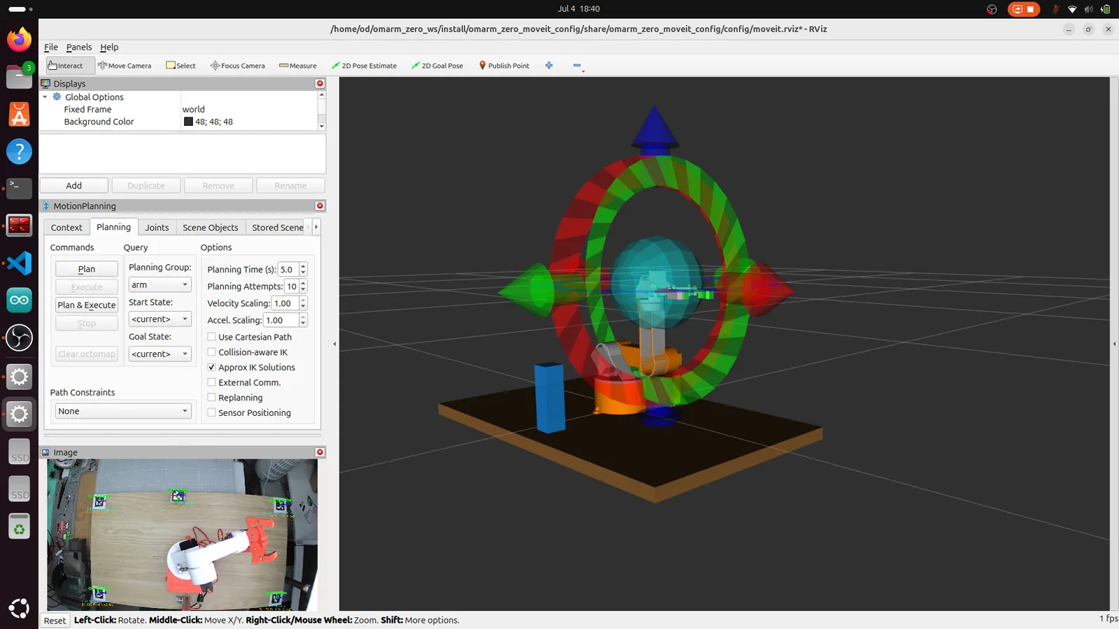
In Part 3, I configured MoveIt with position_only_ik: true, because a 5-DOF arm cannot satisfy an arbitrary 6-DOF pose request. MoveIt’s default IK solver, KDL (Kinematics and Dynamics Library), would fail on most targets if you asked for both position and orientation. Position-only worked for “go to this XYZ”, but a grasp needs more than position. The fingers must approach vertically, pointing straight down. If they come in at an angle, they knock the cube over instead of grasping it.
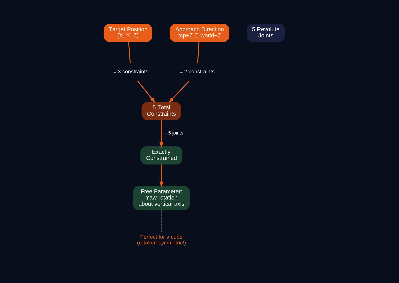
Count the degrees of freedom. A top-down grasp needs:
- The tool position: 3 constraints (X, Y, Z).
- The approach axis pointing straight down: 2 constraints (the axis direction is defined by two angles).
That is 5 constraints total. The rotation about the vertical axis is left free: the 5-DOF arm cannot choose it, so the gripper closes at whatever rotation the solution gives. Five constraints for five joints: the problem is exactly constrained and leaves no slack. The KDL solver cannot solve this mixed goal of position plus approach axis, so I wrote my own solver.
The arm_ik solver
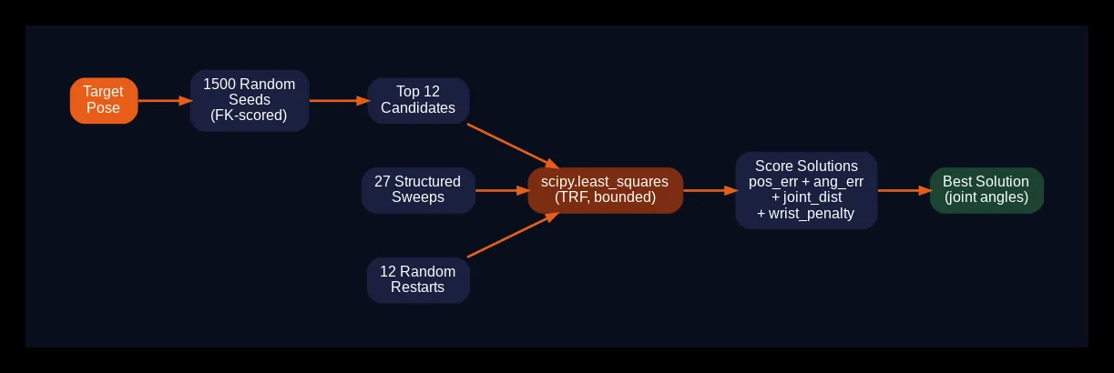
The arm_ik.py module implements this directly. It parses the URDF to build a forward kinematics (FK) chain from base_link through all five revolute joints to the tcp frame (FK: computing the tool pose from given joint angles). The tcp frame (tool center point) is defined in the URDF at the fingertip midpoint, rotated so that its +Z axis is the approach/finger axis. SciPy’s bounded least-squares optimizer then finds joint angles that minimize two residuals at once: the position error (3 components) and the axis alignment error (2 components).
The solver setup:
JOINT_CHAIN = ['Revolute 1', 'Revolute 2', 'Revolute 3', 'Revolute 4',
               'Revolute 5', 'gripper_base_to_tcp']

class ArmIK:
    def __init__(self, xacro_path=None):
        # Parse the URDF chain base_link -> tcp
        if xacro_path is None:
            xacro_path = os.path.join(
                os.path.dirname(__file__), '..', '..', '..',
                'omarm_zero_description', 'urdf', 'omarm_zero.xacro')
        # ... parse joint origins, axes, limits from the URDF ...
        self.limits = np.array(self.limits)   # (5,2) lower/upper bounds

    def fk(self, q):
        """Forward kinematics base_link -> tcp. Returns 4x4 transform."""
        T = np.eye(4)
        qi = 0
        for e in self.chain:
            T = T @ _T(e['R0'], e['xyz'])
            if e['type'] == 'revolute':
                T = T @ _T(_axis_R(e['axis'], q[qi]), np.zeros(3))
                qi += 1
        return T
The forward kinematics chain is built from the URDF joint descriptions, so any change to the URDF (different link lengths, different joint axis directions) propagates automatically. The solver has no hard-coded link lengths or joint axes.
The solver uses a multi-seed strategy. A single initial guess might converge to a local minimum or a bad solution branch. Instead, the solver generates many candidate starting configurations and picks the best result:
def ik_solve(self, target_xyz, approach_dir=(0, 0, -1), seed=None,
             align_axis=2, w_orient=0.1, pos_tol=0.01, ang_tol=15.0,
             quick=False):
    """Solve for [Rev1..Rev5] via bounded least-squares from many seeds.

    Places the tcp at target_xyz AND aligns its axis 'align_axis'
    (2=Z = finger/approach axis) with 'approach_dir' (default straight
    down). Returns list[5] joints, or None if no seed converges."""
    from scipy.optimize import least_squares
    # ... 1500 random samples scored by FK, best become solver seeds ...
    # ... structured sweeps of the joint space ...
    # ... current arm state as a seed for continuity ...
Sample-then-refine seeding: 1500 random joint configurations are scored cheaply by forward kinematics (a position and axis direction check). The most promising candidates become solver seeds, alongside structured sweeps and the current joint state. This finds solution branches that a single seed would miss.
quick=True mode: For reachability scans (“is this height solvable at all?”), a stripped-down solve with fewer samples answers “no” in 1 to 2 seconds instead of 15 seconds. The task uses quick scans first for broad searches and falls back to the full solver before trusting a “no”.
Solution scoring: Among all valid solutions (those that meet both pos_tol and ang_tol), the solver prefers solutions close to the current joint state (for small motions between waypoints) and with a healthy wrist posture. That second criterion gets its own section, because it fixed my most stubborn bug.
8. The two wrist families
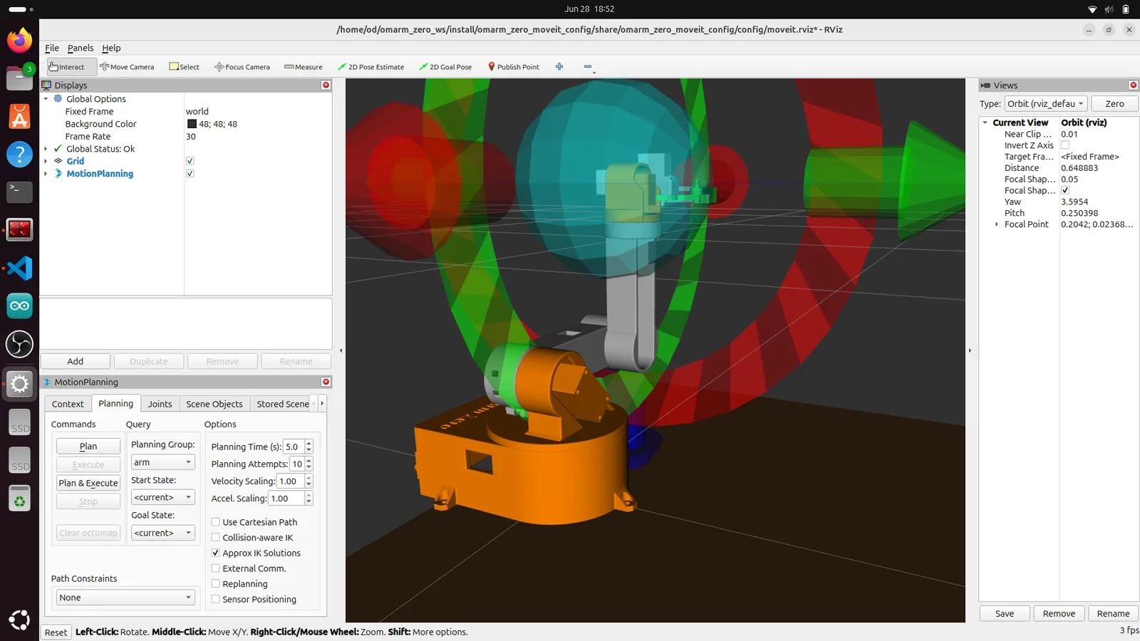
On the real robot, the grasp kept landing a centimeter beside the cube, always on the same side. The visible symptom: the wrist looked twisted around, and that twist caused the offset. The camera calibration checked out (RMS 1 cm), the IK position error was 0 to 2 mm, and the detector found the cube marker. The cause was the wrist geometry.
For a vertical approach axis (fingers pointing straight down), this wrist has two solution families and nothing in between.
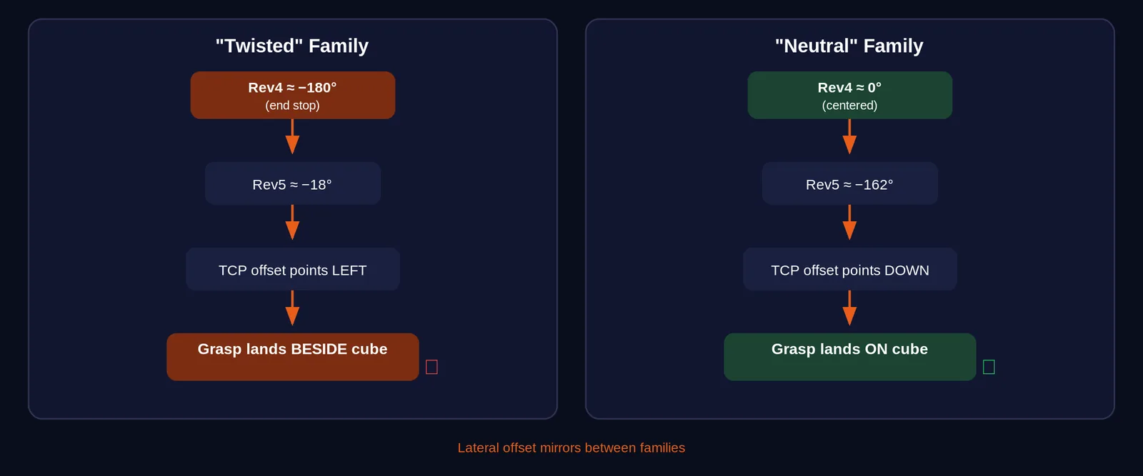
| Family | Forearm rotation (J4, Revolute 4 in the URDF) | Wrist tilt (J5, Revolute 5 in the URDF) | What it looks like |
|---|---|---|---|
| “twisted” | approximately -180 degrees (at its end stop) | approximately -18 degrees | Wrist fully rotated, offset pointing sideways |
| “neutral” | approximately 0 degrees | approximately -162 degrees | Wrist straight, offset pointing correctly |
The solver always found the twisted family first, because its structured seeds started near the joint limits where the twisted configuration lives. And because the tcp frame has a small lateral offset from the wrist axis (the fingertip midpoint is not exactly on the rotation center), the two families mirror that offset. Pick the wrong family and the calibrated offset points the wrong way. The fingers land beside the cube instead of around it.
The fix
Two changes in arm_ik.py solved the problem:
Seed the neutral family explicitly. The solver cannot prefer a branch it never finds. Prototype seeds for the neutral wrist configuration (J4 near zero, J5 near -162 degrees) were added to the seed pool, so the solver always explores both families.
Posture preference in the score. A small penalty on the absolute value of J4 makes the neutral family win whenever it exists. The solver still finds the twisted family as a valid solution, but it ranks lower than the neutral one.
One caveat: the neutral family does not exist everywhere. Joint limits remove it in the back-right zone behind the robot (x < 0 and y < 0, toward marker 2). In the front/center zone (where you would normally place the cube), you get precise neutral-wrist grasps. At the edges, the task warns you (“coarse solution here, grasp may be off”) instead of failing silently. This is a limitation of a 5-DOF arm with a tcp offset.
9. The pick-and-place task
cup_pick_and_place.py runs the whole pick-carry-place cycle. Like /cup_pose, the file is named after the cup I planned to pick first.
The full sequence
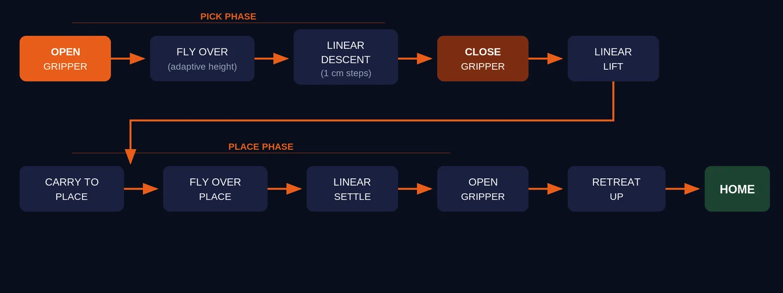
open gripper --> fly over (adaptive height) --> descend linearly --> close gripper
  --> lift linearly --> carry --> fly over place target --> settle linearly
  --> open gripper --> retreat linearly --> home
Why linear descent matters
My first version sent the pre-grasp position and the grasp position as two separate MoveIt joint-space goals. That is the obvious approach: plan to above the cube, then plan to the grasp position. The problem: a joint-space goal interpolates the joint angles, not the gripper position. In Cartesian space (the X, Y, Z coordinates of the table), the gripper therefore moves along an arc instead of a straight line. On the way down, the fingers swept sideways and pushed the cube away before ever closing. I caught this in the Gazebo twin, before the real arm ran the task.
The fix has two halves.
Adaptive fly-over. The task searches downward from grasp_z + approach_height for the highest vertically reachable height above the cube. It uses quick IK scans (the quick=True mode), with a full-solver fallback for any heights the quick mode rejects. Then it plans one normal MoveIt joint-space motion to that fly-over point. Because the fly-over is high above the cube, there is nothing to collide with, and the arc shape does not matter.
Linear descent. From the fly-over point, the task samples Z in 1 cm steps from the fly-over height down to the grasp height. For each step, it solves the IK using the previous step’s solution as the seed. This keeps the solver in the same solution branch (no wrist family flips mid-descent) and produces a continuous joint path. Each step is sent as its own single-point trajectory command to the joint trajectory controller. The tcp moves down a vertical line over the cube in 1 cm steps.
The same method runs in reverse for the lift. An arc during the lift would drag the grasped cube sideways.
The node setup
class CupPickAndPlace(Node):
    def __init__(self):
        super().__init__('cup_pick_and_place')

        self.declare_parameter('grasp_z', 0.04)
        self.declare_parameter('approach_height', 0.10)
        self.declare_parameter('lift', 0.06)
        self.declare_parameter('approach_dir', [0.0, 0.0, -1.0])
        self.declare_parameter('place_x', 0.15)
        self.declare_parameter('place_y', 0.10)
        self.declare_parameter('place_z', 0.10)
        self.declare_parameter('gripper_open', [-1.2, -1.2])
        self.declare_parameter('gripper_closed', [0.9, 0.9])
        self.declare_parameter('home_joints', [0.0, 0.0, 0.0, 0.0, 0.0])

        # 5-DOF IK solver (loads the URDF chain base_link -> tcp)
        self.ik = arm_ik.ArmIK()

        # MoveGroup action client for arm planning
        self._mg_client = None

        # Gripper: direct FollowJointTrajectory action
        self._gripper_client = ActionClient(
            self, FollowJointTrajectory,
            '/joint_trajectory_controller/follow_joint_trajectory')

        # Direct arm-trajectory publisher for LINEAR descent/ascent
        self._arm_traj_pub = self.create_publisher(
            JointTrajectory,
            '/joint_trajectory_controller/joint_trajectory', 10)
Config walkthrough: pick_place_params.yaml (simulation)
The simulation parameters:
cup_pick_and_place:
  ros__parameters:
    grasp_z: 0.07            # fingertip height at grasp
    approach_height: 0.10    # fly-over height ABOVE grasp_z
    lift: 0.06               # linear lift after closing
    approach_dir: [0.0, 0.0, -1.0]   # tcp +Z points straight DOWN
    place_x: 0.15
    place_y: 0.10
    place_z: 0.07
    gripper_open: [-1.2, -1.2]
    gripper_closed: [0.16, 0.16]
    gripper_time_sec: 2.0
    gripper_joints: ['Revolute 6', 'Revolute 7']
grasp_z: 0.07 is the height of the fingertips (the tcp frame) at the moment of grasping. The cube is 10 cm tall, so its top surface is at Z = 0.10. With grasp_z at 0.07, the fingertips descend to 3 cm below the top of the cube, which centers the grip on the upper part of the cube.
approach_height: 0.10 is added to grasp_z to get the initial fly-over height. The task searches downward from this height, so a generous value is safe. The arm flies to the highest reachable point within this range.
approach_dir: [0.0, 0.0, -1.0] specifies that the tcp +Z axis (the finger/approach axis) points straight down in the world frame. This gives a vertical top-down grasp.
gripper_open and gripper_closed are the joint values for the two gripper joints (Revolute 6 and Revolute 7 in the URDF). Negative values open the fingers, positive values close them. The values depend on your gripper geometry and servo calibration (section 11).
Placing at a marker
The place target can be a fixed position or the live-detected pose of another ArUco marker. The real-robot config uses marker 4 (one of the table-corner calibration markers):
place_marker_frame: 'aruco_marker_4'
The task reads the marker’s live position from TF and uses it as the place target. Marker 4 sits at the table corner, outside the arm’s reach. Instead of failing, the task slides the target inward along the base-to-marker line until the vertical IK solves:
# Slide the target radially inward on the base->marker line
# until BOTH the fly-over AND the settle height are solvable.
r = math.hypot(mx, my)
ux, uy = (mx / r, my / r) if r > 1e-6 else (1.0, 0.0)
rr = min(r, 0.22)   # beyond ~22 cm nothing is reachable
while rr >= 0.10:
    tx, ty = ux * rr, uy * rr
    if (self.ik.ik_solve((tx, ty, pz + 0.05), ...) is not None
            and self.ik.ik_solve((tx, ty, pz), ...) is not None):
        found = (tx, ty)
        break
    rr -= 0.01
The task logs the adjustment and the new target (see the log in section 11).
To place the cube somewhere else, print a marker with its own ID (for example ID 5, also 31 mm) and set place_marker_frame: ‘aruco_marker_5’. The detector broadcasts a TF frame for every ID it sees and uses marker_size (31 mm) for any ID missing from marker_sizes. Do not print a second marker with a corner ID: two markers with the same ID give two conflicting positions for one TF frame, and the running corner-marker check from section 5 breaks.
Settle before you open
Releasing the cube at hover height made it drop and topple. The task descends until the cube stands on the table. On the real robot, the cube rides higher in the grip, so I tuned place_z down to 0.01. The arm keeps descending after the cube touches the table, and the fingers slide down its sides for the last centimeter and press it flat. The fingertips end about 1 cm above the table. Only then do the fingers open. Then the arm retreats straight up so the fingers cannot knock the placed cube over.
Fail safely
Every waypoint is IK-checked before any motion starts. An unreachable cube position aborts with a readable hint (“move the cube a few centimeters toward the table center”). Gazebo’s transient START_STATE_INVALID error (MoveIt error code -26) happens when the simulated joint controller (a feedback loop that drives each joint toward its target) briefly overshoots a joint limit after a motion. The task settles and retries it automatically instead of killing the run.
10. Simulation first: Gazebo digital twin with real camera
One command starts the whole simulation pipeline:
ros2 launch omarm_zero_moveit_config cube_gazebo.launch.py \
    camera_info_url:=/absolute/path/to/your_calibration.yaml run_demo:=true

This single launch file starts:
- Gazebo with the robot model and a table with corner markers.
- MoveIt and RViz for motion planning and visualization.
- The real camera pipeline (camera node, ArUco detector, cube pose publisher).
- A cube spawned in Gazebo at the position the real camera reports.
- The grasp-attach helper (for simulated grasping).
- The pick-and-place task itself.
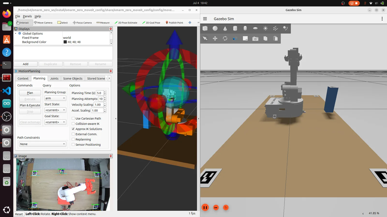
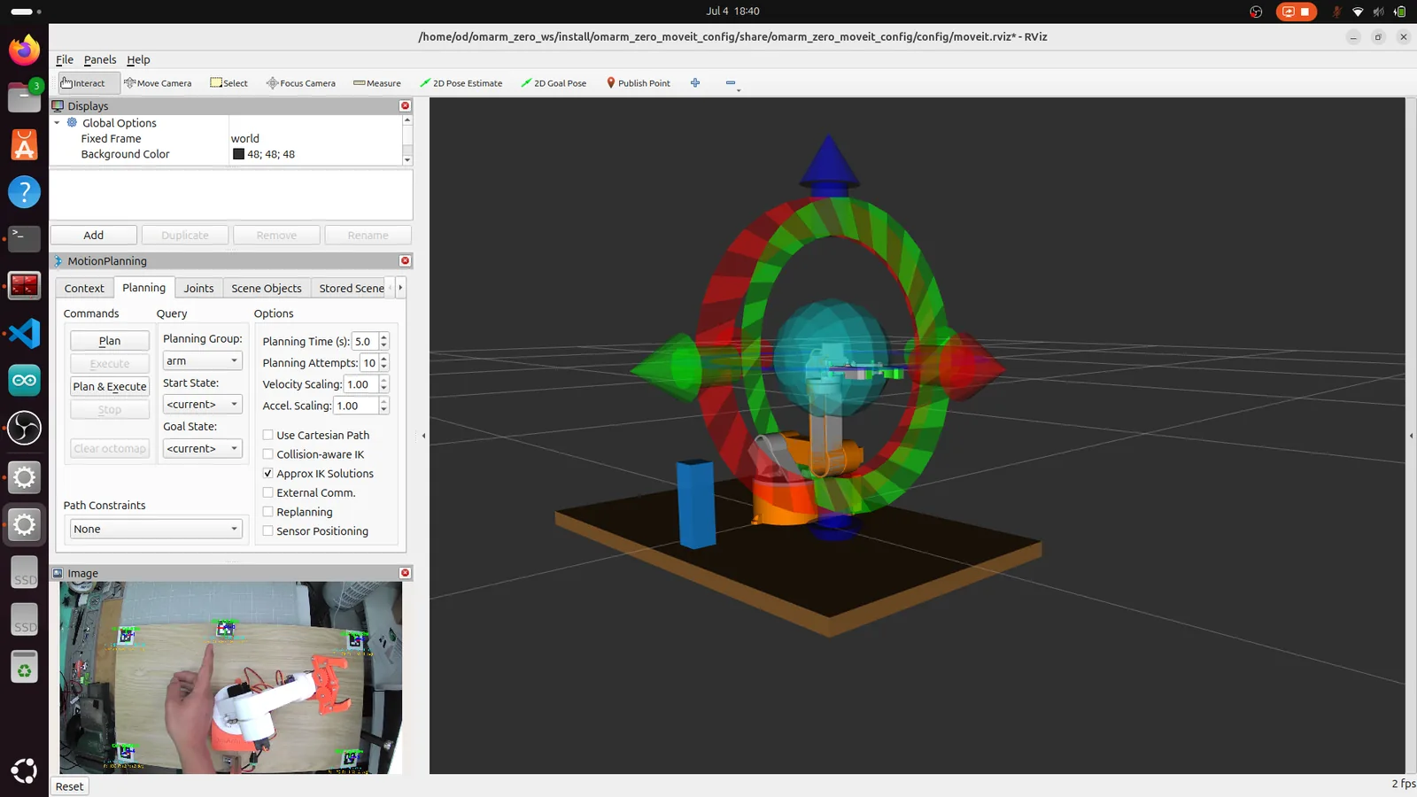
Put your real cube on the real table. Its Gazebo twin appears at the same coordinates, and the simulated arm picks it. Only the arm is simulated. You test the full perception chain (camera, calibration, detection, filtering, TF chain) on real camera data without risking the hardware.
Three simulation tricks
Grasping without grasping physics. A realistic friction grip on a light object is unreliable in Gazebo with the joint control tuned for hobby servos. The simulated fingers either press too hard and launch the cube, or not hard enough and it falls through. A helper node avoids the grip physics: it teleports the cube model to the tcp frame at 50 Hz while the gripper is commanded closed. The cube stays where the fingertips are, with no physics involved.
The 50 Hz update rate matters. I first used the gz service CLI command to set the cube pose on each update, but each CLI call took 150 to 300 ms. At that rate, the cube visibly lagged behind the arm and looked like it was falling off during every motion. The fix was a ROS-Gazebo service bridge (/world/empty/set_pose mapped to the SetEntityPose service) with an async ROS client. The latency dropped to single-digit milliseconds, and the cube stuck to the gripper smoothly.
A gravity-free, collision-free cube. The teleported cube does not need physics. With collisions enabled, the closed fingers pushed the cube on every tick, and it accumulated velocity. When I released it (stopped teleporting), the built-up velocity launched the cube across the Gazebo scene. The fix: disable gravity on the cube model (<gravity>0</gravity> in the SDF, the Simulation Description Format, Gazebo’s model file) and remove its collision elements. The cube is visual only during the grasp. When placed, it stays where the task puts it.
The simulation audits your URDF. My gripper never closed fully in simulation. The URDF said upper=0.3 rad and velocity=0.1 rad/s for the gripper joints, while the commanded close pose was 0.9 rad. Gazebo’s physics engine enforced the joint limits strictly, clamping the commanded position at 0.3 rad. The real servo had tolerated the out-of-range command for weeks. The 0.1 rad/s velocity limit made closing slow as well: at that speed, the 2.1 rad of travel from open (-1.2 rad) to the commanded 0.9 rad takes 21 seconds. My URDF and joint_limits.yaml now allow -1.6 to +1.6 rad at up to 4.0 rad/s for both gripper joints, which covers the full servo range of ±1.57 rad. Set your limits so they cover your own gripper_open and gripper_closed values, rebuild with colcon build, and relaunch. In Gazebo I also lowered the close value step by step: 0.9, 0.54, 0.38 and 0.27 rad each closed the simulated fingers too far. The simulation file now uses 0.16 rad.
Watching the simulation cycle
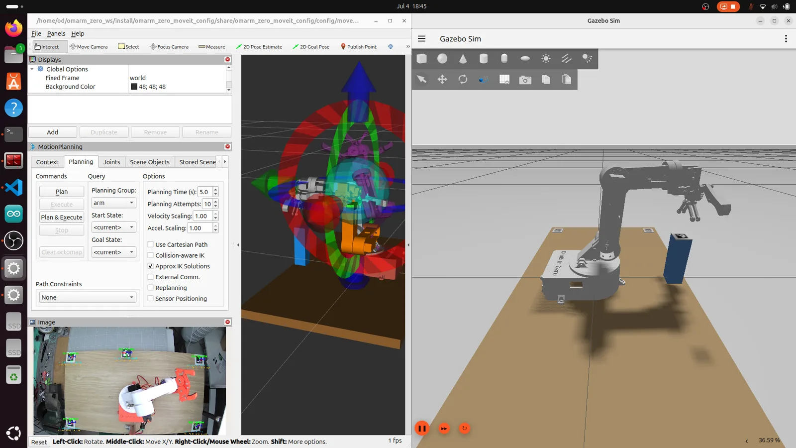
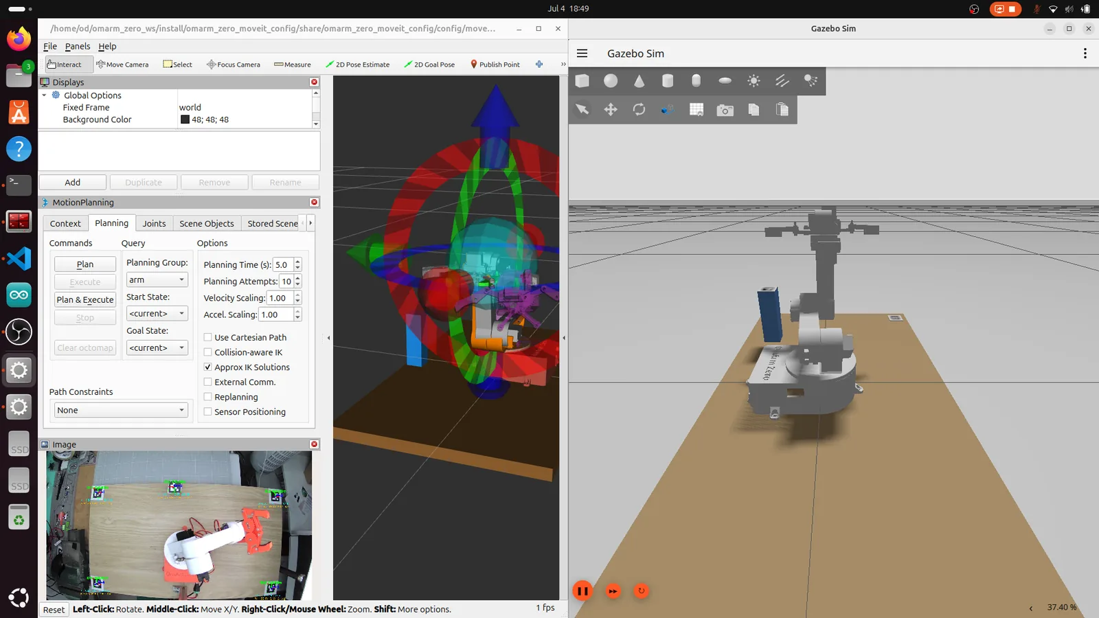
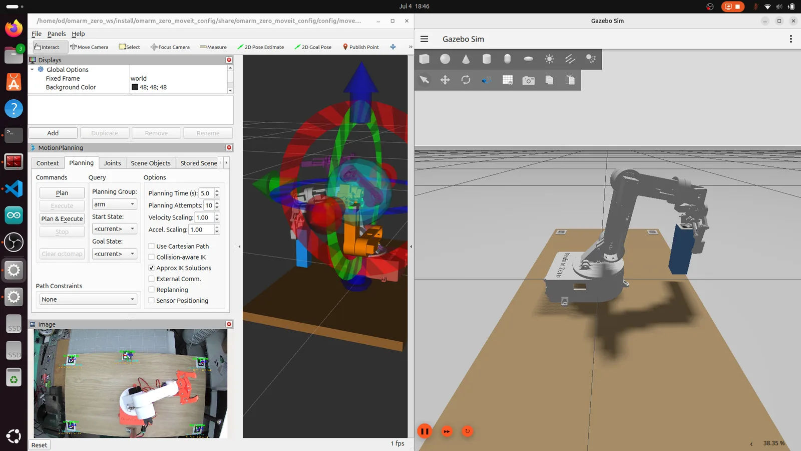
When run_demo:=true, the task runs the sequence from section 9 automatically, and you can follow it in RViz and Gazebo.
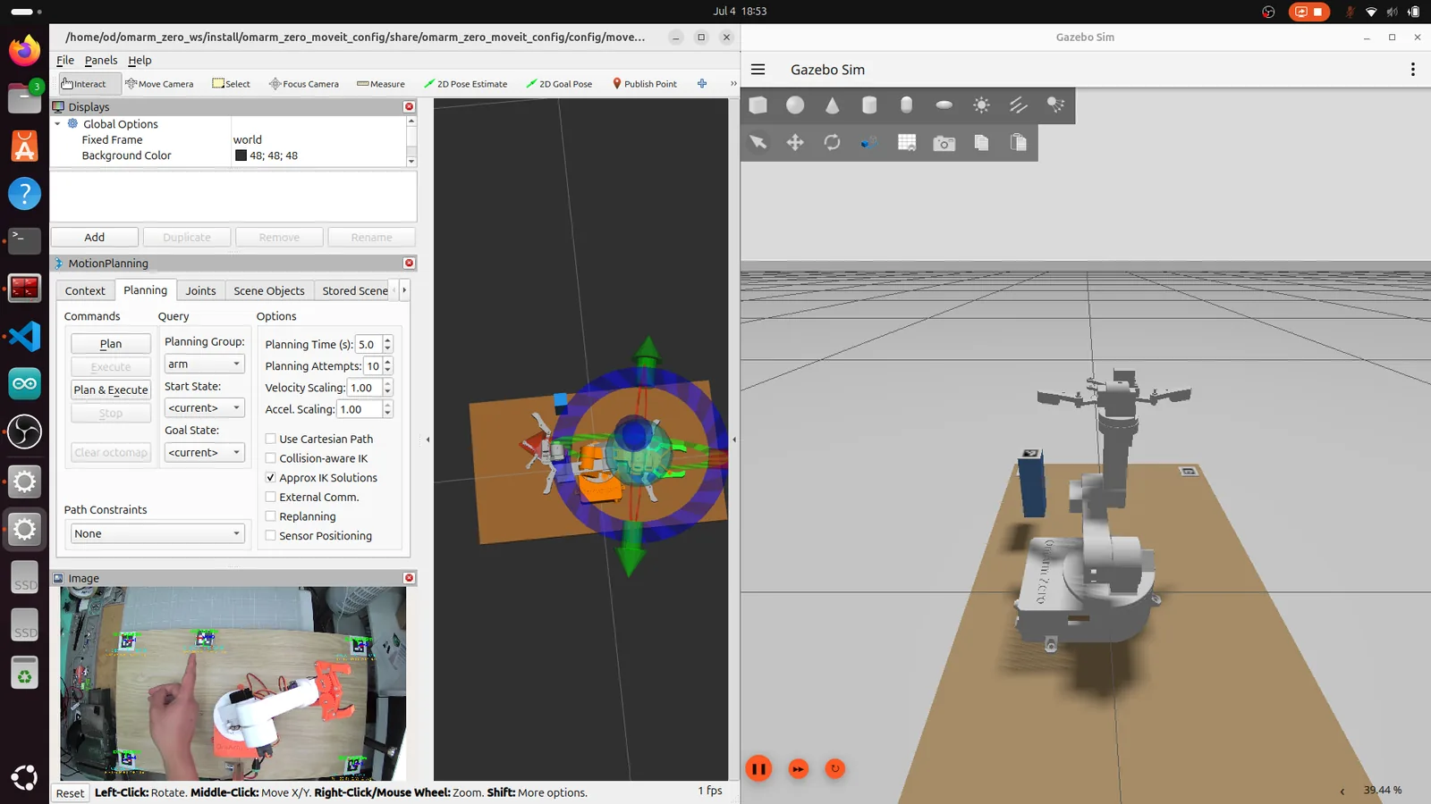
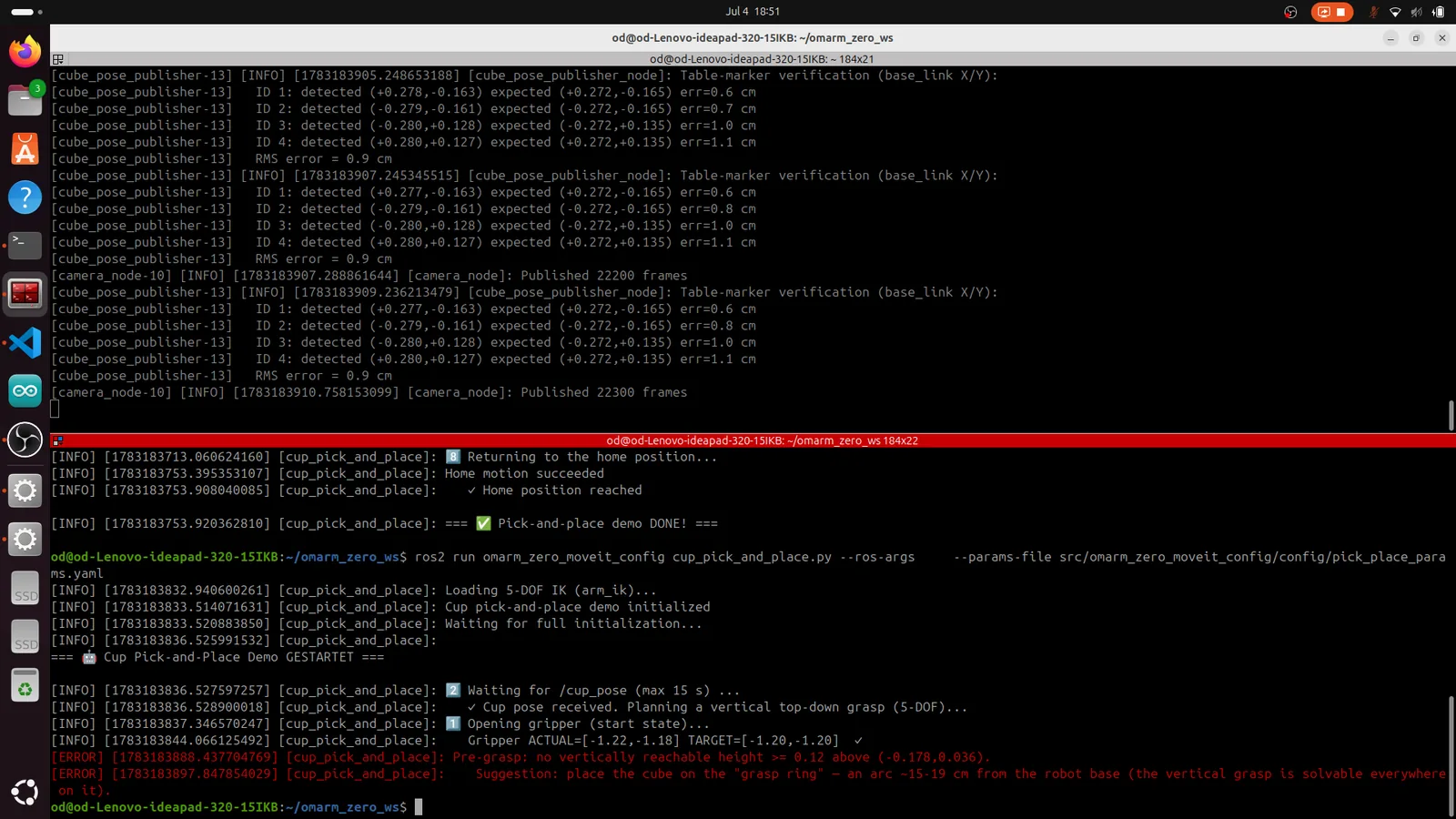
Each step is logged to the terminal with timing and IK metrics. If something fails, the log tells you which step failed and why.
11. Going real: full pipeline on hardware
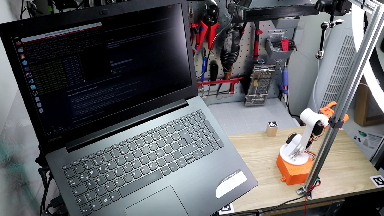
Three terminals (or the bundled cube_real.launch.py):
# Terminal 1: robot (MoveIt + ESP32 bridge)
ros2 launch omarm_zero_moveit_config real_moveit.launch.py \
    transport:=serial use_rviz:=true home_on_start:=true

# Terminal 2: vision (same pipeline as in simulation)
ros2 launch computer_vision_aruco vision_bringup.launch.py \
    camera_info_url:=/absolute/path/to/your_calibration.yaml

# Terminal 3: the task, with the REAL parameter file
ros2 run omarm_zero_moveit_config cup_pick_and_place.py --ros-args \
    --params-file src/omarm_zero_moveit_config/config/pick_place_params_real.yaml
The start flag in Terminal 1 matters on hardware. home_on_start:=true (the default) sends the firmware HOME command at startup and waits 1.5 s (home_wait_sec). omarm_zero_ros2_serial.ino from Part 3 then moves all servos to 90°, the middle of every joint range; the Part 1 firmware homes to 0° instead. Do not use start_at_ros_zero:=true: it sends 0 rad on every joint, which puts J1 at 0° and J2 to J5 at 180°, the end-stop pose of the home_joints warning below.
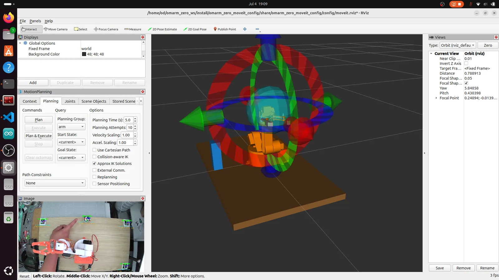
The servos give no position feedback, so after HOME the bridge still assumes 0 rad on every joint. The task opens the gripper first. The bridge fills the arm joints of that command with the stored 0 rad values, so the arm would swing into the end-stop pose at gripper speed. Before you start Terminal 3, choose the goal state home for the arm group in RViz and click Plan & Execute once. If you use cube_real.launch.py instead, it starts the nodes of Terminals 1 and 2 with the same HOME default. Leave its run_demo at false (the default), so the task cannot start before this home move.
What is different on hardware
The real-robot settings are built into the package as separate configurations.
Two parameter files, never mixed. The real-robot parameters live in pick_place_params_real.yaml, separate from the simulation parameters:
# pick_place_params_real.yaml (real robot)
cup_pick_and_place:
  ros__parameters:
    grasp_z: 0.07
    approach_height: 0.10
    lift: 0.06
    approach_dir: [0.0, 0.0, -1.0]
    place_marker_frame: 'aruco_marker_4'
    place_z: 0.01             # settle until cube stands on table
    gripper_open: [-1.57, -1.57]    # full servo range: 180 degrees
    gripper_closed: [1.57, 1.57]    # full servo range: 0 degrees
    gripper_time_sec: 1.0
    home_joints: [0.8, -0.8, -1.2, -0.8, -2.6]   # safe real home
Compare the gripper values: simulation uses [-1.2, -1.2] open / [0.16, 0.16] closed. The smaller close value comes from the Gazebo tuning in section 10. The real robot uses [-1.57, -1.57] / [1.57, 1.57] (full servo range from 0 to 180 degrees, mapped through the hardware bridge).
The home_joints difference is the most dangerous one. The simulation default of [0, 0, 0, 0, 0] is harmless in Gazebo (it is the URDF zero pose). On the real robot, those zeros go through the servo mapping formula deg = 90 + direction * (rad – zero_rad) * 57.3. The result puts every servo at either its 0 or 180 degree end stop. Servos stall at end stops, the 5 V rail (the shared 5 V supply line of all servos) sags, and all servos misbehave at once. The real config uses the proven safe pose [0.8, -0.8, -1.2, -0.8, -2.6], the same home pose as in Part 3.
Speed lives in the firmware, not in MoveIt. The bridge forwards only the final trajectory point to the ESP32. The ESP32 firmware ramps the servos toward that point at its own speed setting. MoveIt’s velocity scaling does not change the servo speed on the real hardware. The bridge switches the firmware speed per command: arm moves use speed 5 (slow and smooth), gripper-only moves use speed 20 (the fingers close fast).
Calibrate the gripper visually. Sweep the gripper servo slowly from 180 to 0 degrees and note two angles: fully open, and closed cleanly on the cube. The bridge maps the gripper with zero_rad 0 and direction -1 (hardware.yaml), so joint value = (90 – servo angle) / 57.3. That gives -1.57 for 180° and +1.57 for 0°; enter your two values as gripper_open and gripper_closed. My gripper ended up using the full servo range after I re-seated the finger on the servo horn (the plastic arm on the servo’s output shaft) one tooth wider.
The wrist-family fix is a real-robot fix. In simulation, both wrist families produce a successful grasp because the simulated gripper is symmetric and the teleportation-based grasping ignores the lateral offset. Only on the real hardware, where the fingers have real geometry and the tcp offset matters, does the twisted family miss the cube.
Watching the real cycle
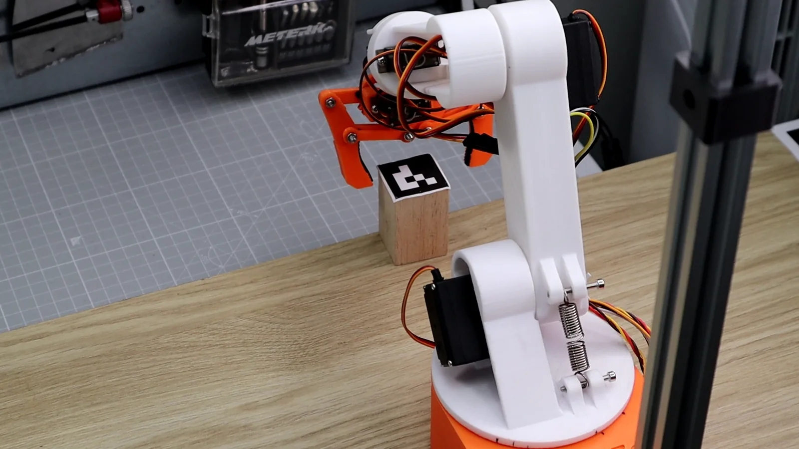
Place the cube with its marker visible to the camera, in the workspace ring roughly 15 to 19 cm from the base. Launch Terminals 1 and 2, move the arm to home in RViz, then start Terminal 3. The task waits for /cup_pose (up to 15 seconds), then begins.
Log of a successful run:
Cup pose received. Planning a vertical top-down grasp (5-DOF)...
   /cup_pose: Marker 0 @ (+0.165, -0.042, +0.050) [world==base_link]
1. Opening gripper (start state)...
2. Pre-grasp (vertically above the cube, z=0.17 = 7 cm above the marker)...
   IK ok: pos_err=1mm, tcp-Z aligned 0 deg from vertical
3. Grasp (LINEAR vertical descent)...
   Descent: 10 steps, z=0.17 -> z=0.07
4. Closing gripper...
5. Lifting (LINEAR up to z=0.13)...
6. Flying OVER the place position (z=0.14)...
   Marker "aruco_marker_4" (+0.272,+0.135) out of reach
   — placing 9 cm short of it: (+0.195,+0.097)
7. Opening gripper (placing)...
8. Returning to the home position...
   Home position reached
=== Pick-and-place demo DONE! ===
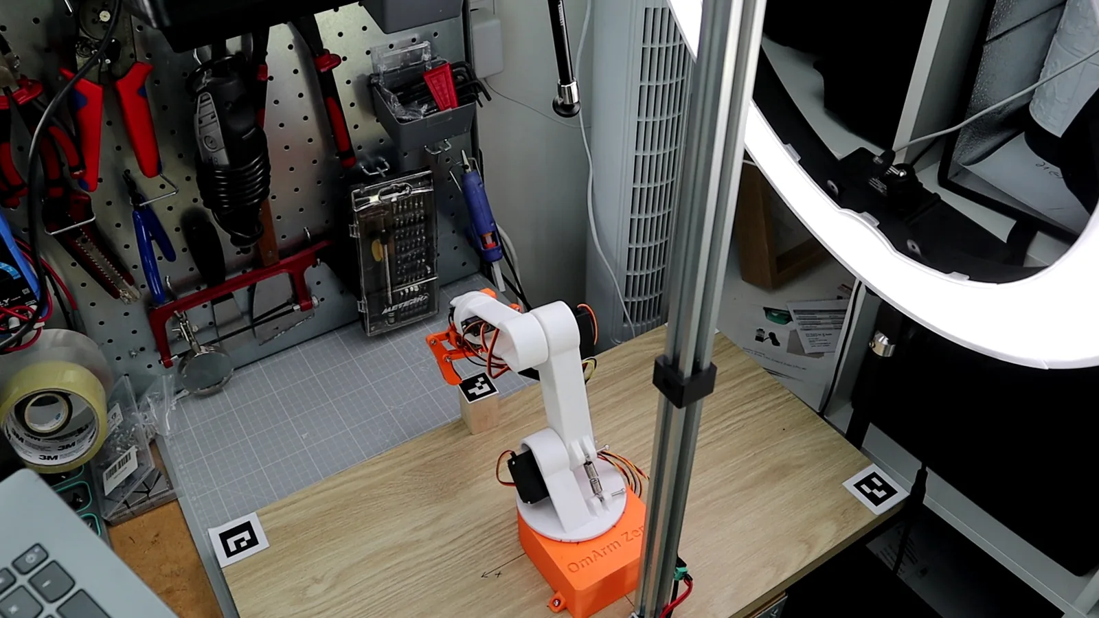
Vertical descent with open fingers.
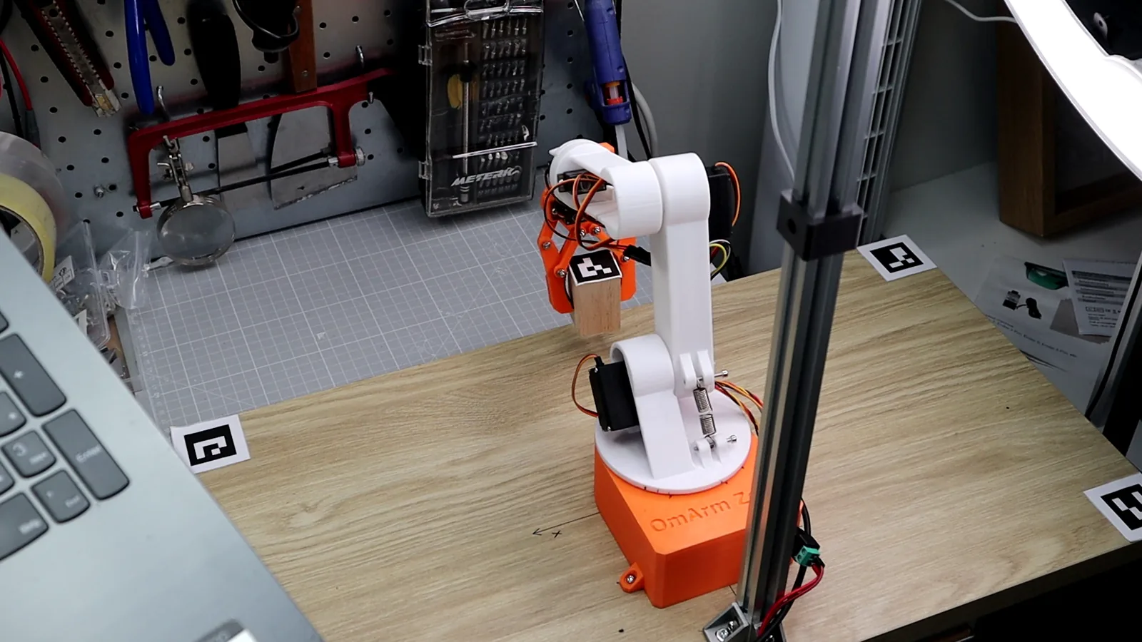
Grasp: the fingers close around the cube.
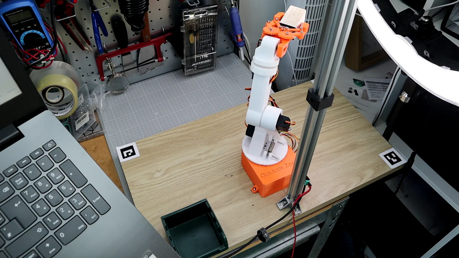
Lift and carry (the carry is a normal MoveIt joint-space motion).

Settle on the table (place_z: 0.01), then the fingers open and the arm retreats and goes home.
12. Troubleshooting
The robot moves to the wrong place, consistently.
This is almost always an extrinsics problem. Check the table-marker RMS in the vision pipeline log. After a calibration, calibrate_extrinsics asks you to check that this value is below 1 cm, and it warns when its own residual exceeds 2 cm. If the RMS climbs above 2 cm, run calibrate_extrinsics again. Also re-measure the table_markers_expected values. A sign error in one measured corner (positive instead of negative Y, for example) corrupts the whole Kabsch solution.
/cup_pose does not update even though the cube moved.
Compare the raw detection with the filtered output. Run ros2 run tf2_ros tf2_echo world aruco_marker_0 to see the raw TF, and ros2 topic echo /cup_pose to see the filtered position. If the raw TF is current but /cup_pose is stuck, the outlier filter is still re-seeding. Wait about one second (it needs 5 consecutive “outliers” before it re-seeds), or restart the vision pipeline. If the raw TF is also stale, the marker is not being detected. Check /aruco/debug_image for lighting problems or a toppled cube (a cube lying on its side hides the marker on top).
Camera fails to open or opens the wrong camera.
The camera re-enumerated after replugging. Run ls /dev/video* to see available devices. Laptops with built-in webcams also claim video indices. After replugging, your USB camera may have moved from video0 to video2. Set camera_id accordingly, or use the stable camera_device path from aruco_params.yaml.
The real robot does not react at all. The bridge says it finished cleanly after one second.
Something else is holding the serial port. The most common cause is an open serial monitor in the Arduino IDE. Run fuser /dev/ttyUSB0 to find the process holding the port, close it, and relaunch. Also check that the ESP32 is powered and the USB cable supports data (some USB cables are charge-only).
“No vertically reachable height” or the task aborts before moving.
At that cube position, no vertical approach exists for this 5-DOF arm. The vertical-grasp workspace is a ring roughly 15 to 19 cm from the base. Closer positions hit the arm’s minimum reach. Farther positions exceed the maximum reach for a vertical approach. The task probes the neighborhood and prints a concrete suggestion: “push the cube 3 cm toward the marker-2 corner (reachable at (-0.03, -0.18))”. Marker 2 is the back-right corner. Inside the grasp ring, this message should not appear.
Gripper barely closes or takes very long in simulation.
Your URDF gripper joint limits do not cover the commanded close pose, so Gazebo clamps the close command and the low velocity limit makes it slow. Fix the limits as described in section 10 (URDF and joint_limits.yaml), rebuild with colcon build, and relaunch.
Grasp consistently lands beside the cube on the real robot.
This is the wrist-family problem from section 8. Check the forearm rotation (J4, logged as Revolute 4) in the log or in RViz. If it is near -180 degrees, you are in the twisted family. The posture-preferring IK in this package chooses the neutral family wherever it exists. Keep the cube in the front/center zone (positive X, small Y) where the neutral family is available.
Power loss on the robot side during operation.
Restart real_moveit.launch.py as in section 11 and move the arm to home in RViz once before you run the task again. This re-syncs the physical arm with the software state. The bridge re-applies its speed setting. If the 5 V rail sagged during the power event, check that all servos still respond before running the task again.
RViz shows the cube at a different position than the real cube.
Check the camera calibration first: ros2 topic echo /camera/camera_info –once should show your focal lengths, not defaults. Then check the marker size in the config. If the printed marker is 30 mm but the config says 31 mm, all distances will be off by about 3 %.
13. FAQ
Can I skip the simulation and go straight to hardware? You can, but the Gazebo twin caught four bugs before any servo was at risk (sections 9 and 10), and simulation and real robot run the same task code.
Does this work with a different camera height or table? Yes. That is what the two calibrations absorb. Re-run the intrinsic calibration if the camera model or resolution changes. Re-run the extrinsic calibration (four markers, one command) if the camera mount moves. Re-measure the marker corner positions if the table changes.
My gripper geometry is different. What do I retune? Three values: the tcp frame origin in the URDF (set it to your fingertip midpoint), the gripper_open and gripper_closed values (one visual servo sweep, section 11), and grasp_z for your object height. Everything else adapts through the URDF-based FK chain.
What happens if the cube is moved during the grasp? The task reads the cube position once at the start and plans the whole sequence from that snapshot. It does not track the cube during the descent. If someone moves the cube after the arm starts descending, the gripper closes at the old position and misses the cube. For a desktop demo, this is fine. A production system would need continuous tracking and replanning.
Can I use this with a depth camera instead of ArUco markers? In principle, yes. A depth camera (like the RealSense) gives you point clouds, and you can detect objects by their shape instead of by a marker. The perception pipeline would be different (point cloud segmentation instead of ArUco detection), but the IK solver, the pick-and-place task and the linear descent logic stay the same. The interface is the /cup_pose topic, so you can also swap in a YOLO detector (a neural network that finds objects in images) or a point cloud pipeline later. Any node that publishes a PoseStamped message there will work.
14. Series wrap-up
Part 1: Mechanics, electronics, ESP32 firmware and web control. A desktop arm for about $48 in parts that moves when you drag sliders on your phone. Read Part 1
Part 2: URDF/Xacro, RViz visualization, and a Gazebo digital twin with physics simulation. The arm existed in software for the first time. Read Part 2
Part 3: MoveIt 2 motion planning, from mock hardware to real servos over a serial bridge. The arm went where you told it; on the real servos, the bridge drives straight to the goal of each planned path. Read Part 3
Part 4: Camera calibration, ArUco perception, a custom 5-DOF grasp IK, and a pick-and-place pipeline tested on the real arm. The arm now takes its target from the camera instead of from you.
The full chain now runs on the real arm. The camera finds the marker, the calibration turns pixels into robot coordinates, and the IK solver computes joint angles. MoveIt plans a collision-free path, and the serial bridge drives the servos.
Resources
- Part 1: Build a 6-DOF (5+1 Gripper) Robotic Arm with ESP32 Web Control: mechanics, electronics, firmware.
- Part 2: ROS 2 URDF Tutorial: RViz and Gazebo: the robot model.
- Part 3: MoveIt 2 Tutorial: Motion Planning and Real Robot Control: planning and the serial bridge.
- OmArm Zero ROS 2 Workspace (shop): the complete workspace for Parts 2 to 4.
- OmArm Zero YouTube: the video series.
- OmArm Zero GitHub: the repository.