
يحتوي هذا المقال على روابط تسويق بالعمولة مُعلَّمة بعلامة *. بصفتي شريكًا في برنامج Amazon Associates، أربح من عمليات الشراء المؤهلة، دون أي تكلفة إضافية عليك. يساعد ذلك على إبقاء الشروحات مجانية.
سلسلة OmArm One
- الجزء 1: البناء والتحليل الإستاتيكي والحمولة (هذا المقال).
- الجزء 1.5: قيادتها بوحدة تحكم الألعاب.
- الجزء 2: التوأم الرقمي، وURDF في RViz وGazebo.
- Part 3: MoveIt 2 and ros2_control on real hardware (video).
- الجزء 4: الالتقاط والوضع بالرؤية الحاسوبية (قريبًا).
- الجزء 5: الذكاء الاصطناعي: الإمساك بالأشياء بالاسم وبالصوت (قريبًا).
جديد هنا؟ هذه الذراع هي خليفة OmArm Zero، المشروع الذي كلّف 50 $ وانطلقت منه هذه السلسلة. لا تحتاج إلى Zero لتتابع، لكن قرارات التصميم أدناه تصبح أوضح إذا عرفت من أين جاءت.
يُحمَّل الفيديو من YouTube (Google)، وقد يضع ملفات تعريف الارتباط (Cookies). سياسة الخصوصية
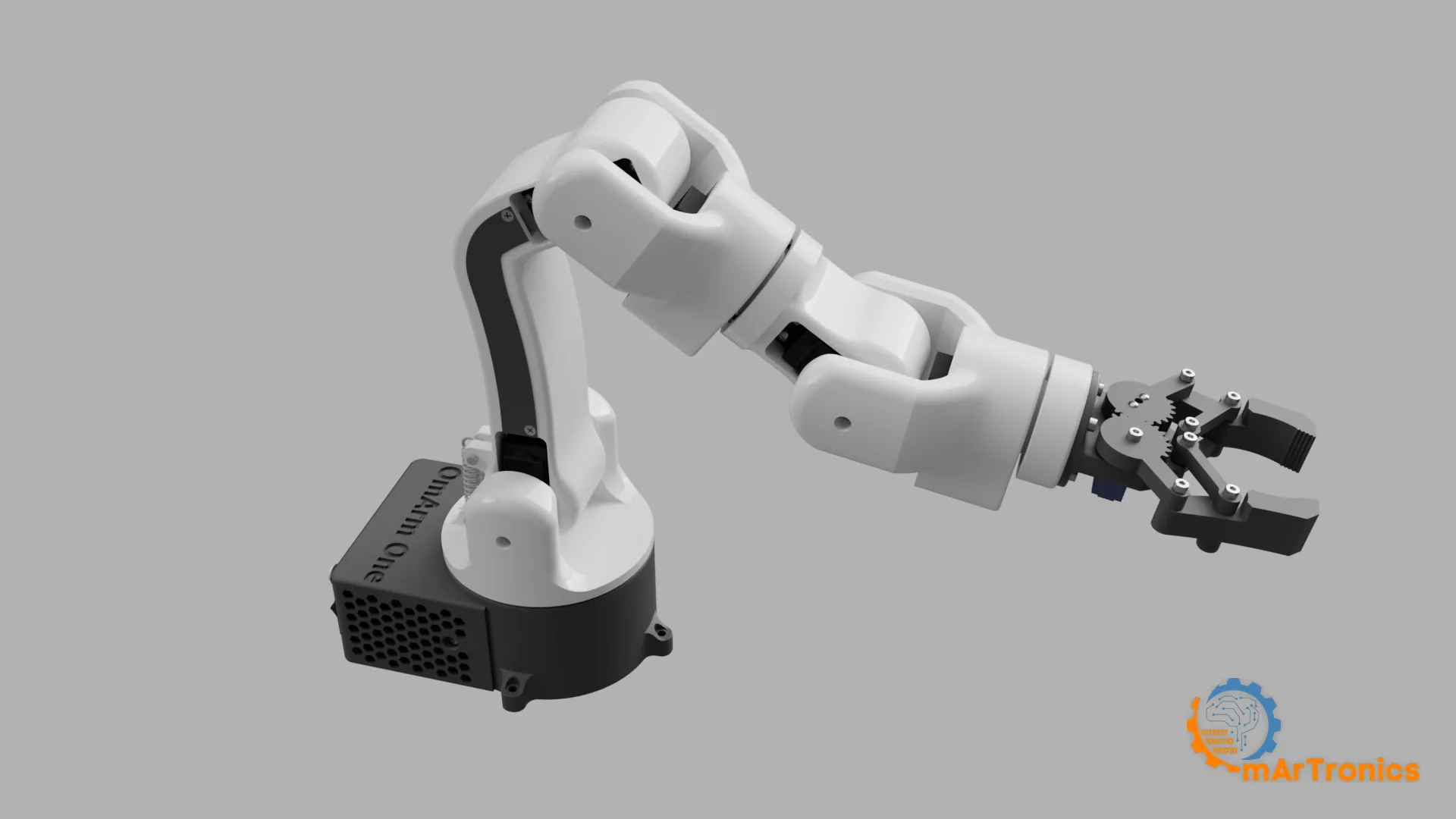
هذه ذراع روبوتية مصنوعة بالطباعة ثلاثية الأبعاد (3D)، فيها ستة مفاصل وقابض. الرقم 7 في 7-DOF (درجات الحرية، أي عدد المحاور التي يُدار كلٌّ منها بشكل مستقل) يحتسب القابض: ستة مفاصل لتحديد الموضع (J1 إلى J6) إضافة إلى محرك القابض (J7). كل مفصل يتحمل عزم انحناء يدور على محمل كروي فولاذي، فلا تنقل مجموعات تروس السيرفو سوى عزم الدوران. العزم هو الأثر الدوراني لقوة حول محور: القوة مضروبة في ذراع الرافعة. تستند القاعدة إلى محمل دفعي 51110 ومحمل قطري 6806ZZ؛ أما مفاصل الميل (Pitch) فتستخدم ترتيبًا من نوع ثابت-حر (Fixed-Loose) مبنيًا حول محمل 695ZZ، وهو مشروح في القسم 5. يبلغ مدى وصول الذراع 485 mm، وتحمل 200 g اسميًا و250 g كحد أقصى عند نصف قطر عمل 300 mm، ويبلغ وزنها 1283 g.
تأتي قيم عزم الدوران من نموذج كتلي في CAD يمسح فضاء المفاصل بحثًا عن أسوأ وضعية لكل مفصل. ويطبّق جدول الحمولة النموذج نفسه عند 63 % من عزم التوقف، وسكربت التحليل الذي أنتج الاثنين موجود في المستودع.
نظرة سريعة
الوقت اللازم: 15 ساعة و6 دقائق من الطباعة موزعة على لوحتي طباعة بطابعة Bambu Lab P1S، دون مراقبة. ويضيف التجميع والاختبار نحو ثلاث ساعات.
التكلفة الإجمالية: من 210 إلى 360 € تقريبًا بأسعار أغسطس 2026 إذا اشتريت كل القطع جديدة وبعبوات كاملة. تشكّل محركات السيرفو DS3240 الستة من 40 إلى 43 % من ذلك. القسم 6 يفصّل المجموع، بما في ذلك الرقم الأدنى إذا كنت تملك مسبقًا طابعة وخيط طباعة (Filament) ومزود طاقة 6 V.
مستوى الصعوبة: متوسط. إذا كنت قد بنيت OmArm Zero فهذا العمل من النوع نفسه، لكن بقطع أثقل ومحامل مركّبة بالكبس (Press-Fit).
السلامة: تستطيع الذراع أن تقرص بقوة تكفي لإيلامك، ومزود الطاقة يُخرج تيارًا عاليًا. القسم 7 يبدأ بخمس عادات تغطي ذلك. اقرأها قبل التشغيل الأول.
ما ينبغي أن تكون متمكنًا منه مسبقًا: تحميل البرنامج على ESP32 من Arduino IDE، وتقطيع ملف STL في برنامج التقطيع (Slicer). ستقرأ أيضًا قياسات القدمة (Caliper) أكثر من مرة. لا تحتاج إلى رياضيات الروبوتات. وتتكرر ثلاثة مصطلحات في المقال كله. عزم التوقف (Stall Torque) هو أعلى عزم دوران يستطيع السيرفو إنتاجه؛ وعند هذا الحمل يتوقف عمود الخرج عن الدوران. أما ذراع السيرفو (Horn) فهي القطعة البلاستيكية المحزّزة التي تُثبَّت بإحكام على عمود خرج السيرفو. الخلوص (Backlash) هو اللعب الحر الذي تشعر به عندما تهزّ مجموعة تروس يُفترض أنها مقفلة. الأقسام 4 و 5 هي الجزء النظري؛ يمكنك تخطيها في القراءة الأولى والعودة إليها حين يفاجئك رقم ما أثناء البناء.
الأدوات التي ستحتاجها (القسم 6 يسرد كل عناصر التثبيت):
- مفتاح سداسي (Allen) مقاس 2.5 mm؛ فالبراغي الأربعة عشر M3 ذات الرأس الأسطواني (Socket-Head) تحتاجه كلها.
- مفتاح ربط أو لقمة مقاس 8 mm للمسامير الملولبة الثلاثة M5 وصواميلها.
- مفكات Phillips مقاس PH0 وPH1 للبراغي الـ63 ذاتية التسنين (Self-Tapping) وللبرغي M1.6 في القابض.
- مفك Pozidriv مقاس PZ1 لبرغيَي M3 من نوع Pozidriv.
- قدمة (Caliper) لقياس مقاعد المحامل في الخطوة 3 من القسم 7.
- كاوية لحام وأنابيب انكماش حراري لتوصيلات مزود الطاقة في القاعدة؛ وتُستخدم الكاوية أيضًا لتركيب الحشوات الملولبة الحرارية الثماني M3 في القابض.
- طابعة ثلاثية الأبعاد (3D) بسرير طباعة 256 mm؛ والقطع موزعة لتناسب Bambu Lab P1S.
الملفات التي ستحتاج إليها: ملفات STL والبرنامج الثابت (Firmware) ومشروع الطباعة في Bambu Studio. الحزمة متوفرة في المتجر والبرنامج الثابت على GitHub؛ والرابطان موجودان في قسم الموارد في النهاية.
ابدأ من هنا:
- اطلب القطع؛ القسم 6 يحتوي على جدول الشراء مع الأسعار.
- ابدأ طباعة اللوحتين أثناء الانتظار؛ القسم 5 يحتوي على الإعدادات.
- وصّل أسلاك القاعدة قبل أي تجميع؛ القسم 8 يحتوي على التوصيلات، والخطوة 1 في القسم 7 تشرح لماذا تأتي أولًا.
- اقرأ عادات السلامة الخمس في بداية القسم 7، ثم نفّذ خطوات البناء من 1 إلى 16.
- عندما يتصرف شيء على نحو غير متوقع، انتقل إلى القسم 11.
1. لماذا نبني ذراعًا روبوتية بالطباعة ثلاثية الأبعاد (3D) من الصفر (مرة أخرى)؟
كان من المفترض أن تكون OmArm Zero تجربة لمرة واحدة: ذراع واحدة بُنيت لمعرفة ما إذا كان صنعها ممكنًا بتكلفة زهيدة. خمسة مفاصل وقابض، ومدى وصول 303 mm، وحمولة 100 g (و150 g مع نابض الكتف)، ونحو $50 ثمنًا للقطع، ويُتحكَّم بها من متصفح الويب عبر واجهة يقدّمها ESP32. وانتهى بها الأمر إلى أن أصبحت محور سلسلة من أربعة أجزاء: البناء، وتصدير URDF، وتخطيط الحركة في ROS 2، والرؤية الحاسوبية. وURDF (Unified Robot Description Format) ملف يصف وصلات الذراع ومفاصلها. أما ROS 2 (Robot Operating System 2) فإطار برمجي يربط المستشعرات وبرامج تخطيط الحركة ووحدات قيادة المحركات. وبنهاية ذلك كانت لدي قائمة طويلة بما كنت سأفعله بشكل مختلف.
ما أردته بعد ذلك ذراعٌ لم أعد أوجّهها بيدي. الذراع التي تتبع أشرطة التمرير (Sliders) يمكن أن تكون لينة وتقريبية، لأن الإنسان يصحح حركتها. أما الذراع التي تنفذ تعليمات مخطط الحركة دون إشراف فلا يمكن أن تكون لينة ولا تقريبية.
يجب أن ترفع 200 g طوال اليوم و250 g عند الطلب. ويجب أن تثبّت هذا الحمل في أي مكان ضمن نصف قطر عمل 300 mm، وفي أسوأ وضعية عند نصف القطر هذا، دون أن يسخن أي سيرفو بشكل زائد. تمكنت Zero من حمل 150 g وهي ممدودة بالكامل مع نابض يساعد الكتف، وكان ذلك أقصى ما تستطيعه.
يجب أن تكون لها ستة مفاصل لا خمسة. خمسة مفاصل تتيح لك وضع القابض في مكان ما. أما ستة فتتيح لك وضعه هناك من اتجاه تختاره، وهذا الفرق هو ما يحدد هل تنجح الأجزاء من 3 إلى 5 من هذه السلسلة أصلًا. فالكاميرا التي تجد جسمًا تخبرك أيضًا بكيفية توجّهه.
كل مفصل يتحمل عزمًا يحصل على محمل. هذا المتطلب يحدد شكل التصميم أكثر من أي متطلب آخر في القائمة.
في Zero كانت القاعدة منصة مطبوعة مثبتة بالبراغي على ذراع السيرفو (Horn)، مع محمل 6806ZZ صغير واحد يثبّت العمود. وعندما تمتد الذراع، تحاول الجاذبية أيضًا أن تُميل القاعدة، وكان عزم الإمالة هذا يمر عبر ذراع السيرفو إلى مجموعة تروس السيرفو. كان ذلك مقبولًا لذراع Zero التي تزن 535 g، لكنه لا يصلح لذراع أثقل بمدى وصول أكبر. فالعزم يزداد بزيادة الوزن ومدى الوصول معًا، وعمود خرج السيرفو مصمم لنقل عزم الدوران فقط.
في One ينقل السيرفو عزم الدوران وتتحمل المحامل كل ما عدا ذلك. يتحمل محمل دفعي 51110 وزن الذراع عند القاعدة، ويتحمل محمل قطري 6806ZZ عزم الإمالة. ويحصل كل مفصل ميل على ترتيب محامل ثابت-حر، بحيث تُسند الشوكة المطبوعة من الجانبين. القسم 5 يشرح كل واحد منها بالتفصيل.
يظهر الفرق قبل تشغيل أي شيء. إذا هززت من جهة المعصم ذراعًا مركّبة مباشرة على ذراع السيرفو (Horn)، تتحرك مجموعة التروس ضمن خلوصها. أما إذا ضغطت على هذه الذراع للأسفل وهي ممدودة بالكامل، فيذهب الحمل إلى محامل القاعدة. القسم 10 يحوّل ذلك إلى اختبار يمكنك تنفيذه، بما في ذلك الاتجاه الذي تدفع فيه والاتجاه الذي لا يخبرك بشيء.
قاعدة واحدة انتقلت من Zero: كل مكوّن يُختار بالحساب أولًا ثم بالكتالوج. يأتي تحليل عزم الدوران قبل قائمة القطع، وجدول الحمولة قبل اختبار الحمولة، وكل رقم معلن للحمولة مرتبط بنصف قطر عمل محدد. وكما في Zero، صُممت الذراع للسلسلة كلها منذ البداية، ولهذا يبدو بروتوكول الاتصال التسلسلي واصطلاحات المفاصل وشكل مساحة العمل على ما هي عليه.
2. ما الذي تستطيع الذراع فعله حتى الآن

حركة بلا اندفاعات مفاجئة
كل حركة من نقطة إلى نقطة تتبع منحنى خماسيًا منسَّقًا (Quintic Profile)، وهو منحنى موضع من الدرجة الخامسة اختير بحيث تبدأ السرعة والتسارع كلاهما من الصفر وينتهيان عنده. تتشارك المفاصل السبعة كلها مدة واحدة، فتبدأ معًا وتصل معًا. وهذا أهم في ذراع بطول 485 mm منه في ذراع صغيرة، لأن الاندفاع المفاجئ عند الكتف يتحول إلى ضربة سوط واضحة عند أطراف الأصابع.
سحب شريط التمرير مشكلة مختلفة لها حل مختلف. فالهدف يواصل الحركة بينما تلاحقه الذراع، لذا لا جدوى من تخطيط مسار. بدلًا من ذلك يتبع كل مفصل الهدف بتسارع محدود، ويكبح مبكرًا بما يكفي حتى لا يتجاوز الهدف. يلتزم المساران بحدود السرعة والتسارع نفسها، وكلاهما محدود في كل دورة تحكم، فلا يمكن لطلب واي فاي (Wi-Fi) متعثر أو استدعاء HTTP بطيء أن يتحول إلى خطوة واحدة ضخمة. نواة الحركة رياضيات بحتة بلا أي اعتماد على Arduino، لذا يمكن ترجمتها برمجيًا (Compile) وتشغيلها على حاسوب شخصي باستخدام ملف الترويسة (Header) نفسه الذي ينفذه ESP32.

نموذج أمان لذراع قادرة على إيذائك
لا تملك هذه الذراع تغذية راجعة للموضع، لذا لا تعرف بعد إعادة الضبط (Reset) أين هي. ويتعامل البرنامج الثابت مع ذلك كمشكلة أمان. لا شيء يتحرك عند الإقلاع. والموضع المفقود يجب أن يؤكده إنسان قبل أن تعود محركات السيرفو للعمل. وتُمدَّد أول حركة بعد أي إقلاع إلى أربع ثوانٍ على الأقل، ويبقى إيقاف الطوارئ مفعّلًا حتى تحرره بنفسك. القسم 8 يشرح النموذج كاملًا، بما في ذلك حالة إعادة الضبط التي تفاجئ كثيرين: رفع البرنامج الثابت يُعدّ انقطاعًا للطاقة.
دقة أنعم من النطاق الميت (Dead Band) للسيرفو
تُشغَّل محركات السيرفو الستة الخاصة بالمفاصل عبر لوحة قيادة السيرفو PCA9685 عند 250 Hz، أي خمسة أضعاف التردد التقليدي للسيرفو. وعندها تساوي خطوة PWM واحدة (PWM أو تعديل عرض النبضة: عرض نبضة متكررة يخبر السيرفو بزاوية الهدف) 0.086 درجة عند المفصل. أما DS3240 فيبلغ نطاقه الميت، أي أصغر تغيير في الأمر يستجيب له السيرفو، 0.27 درجة. صار النطاق الميت للسيرفو نفسه هو ما يحدد حد الدقة، واختبار قابلية التكرار في القسم 10 يقيس أداء الذراع مقارنةً بهذا الحد الأدنى. القسم 8 يشرح المنطق وراء ذلك والفخ الكامن فيه.

ثلاثة برامج ثابتة وتوصيلات واحدة
اللوحة نفسها والقنوات نفسها والاصطلاحات نفسها تخدم ثلاث نسخ: النسختان أدناه، إضافة إلى البرنامج الثابت الخاص بيد التحكم (Game Controller) من الجزء 1.5.
البرنامج الثابت لتطبيق الويب يُنشئ نقطة وصول واي فاي (Wi-Fi) خاصة به ويقدّم واجهة تحكم. فيها سبعة أشرطة تمرير للمفاصل، وتحكم في السرعة، وأمر للعودة إلى وضعية البداية (Home)، وإيقاف طوارئ، ومحرر تسلسلات صغير. يسجّل المحرر الوضعيات ويعيد تشغيلها مع تأخير قابل للضبط. وتُصدَّر التسلسلات وتُستورد كملفات، فيبقى العرض الذي جهزته مرة واحدة حتى بعد إعادة التحميل على اللوحة. والواجهة مخزنة في ESP32 نفسه.
البرنامج الثابت التسلسلي لـ ROS 2 يستغني عن الواي فاي وتطبيق الويب ونظام الملفات، مما يبقيه صغيرًا ويُبعد كل ما قد يُربك توقيت السيرفو. ويضيف ما يحتاجه مخطط الحركة: تتبع المسار، حيث يُحمَّل المسار كاملًا ثم يُتحقق منه بالكامل قبل أن يتحرك أي شيء. يشمل التحقق نطاقات المفاصل، وحد السرعة، والتوقيت، وما إذا كان المسار يبدأ من حيث تقف الذراع بفارق لا يتجاوز خمس درجات. وإذا فشل التحقق تحصل على رفض مع ذكر السبب، ولا يتحرك شيء. قاعدة التحقق قبل التنفيذ هذه هي الجزء الذي أنا أكثر رضا عنه. وقد جاءت من مشاهدتي لجسر ROS 2 التسلسلي في Zero وهو ينفذ بصمت آخر نقطة طريق (Waypoint) فقط من الخطة.
التبديل بينهما يعني إعادة تحميل البرنامج على اللوحة. ويبقى موضع الذراع المخزَّن محفوظًا، فلا تتحرك الذراع عند تبديل البرنامج الثابت. ويُترجَم كلاهما برمجيًا دون أخطاء أو تحذيرات على نواة ESP32 الحالية: تشغل نسخة تطبيق الويب 80 بالمئة من قسم التطبيق البالغ 1.25 MB (منطقة الذاكرة الوميضية التي تحمل البرنامج)، والبرنامج الثابت التسلسلي لـ ROS 2 نسبة 26 بالمئة.
3. إلى أين تتجه هذه السلسلة
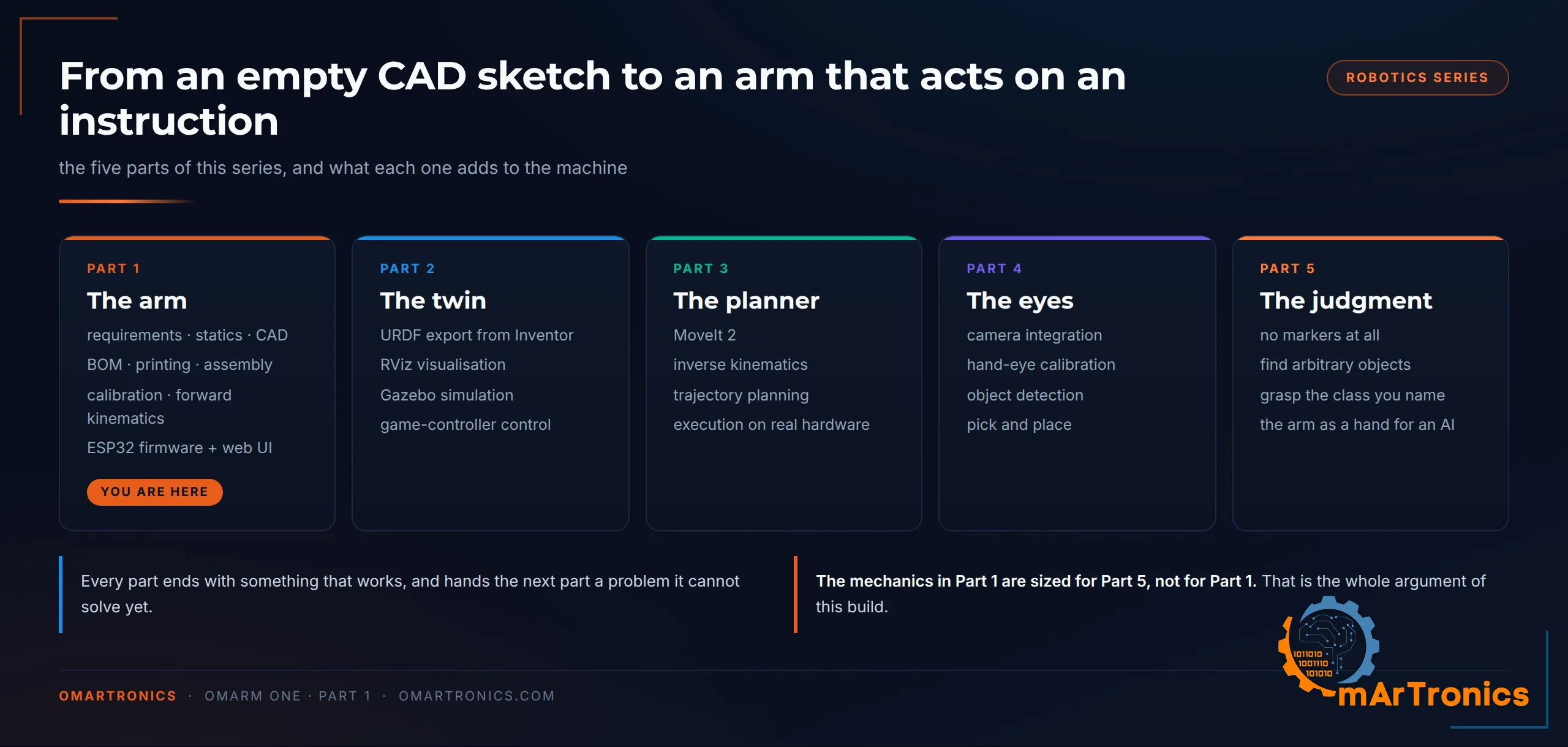
تتكون السلسلة من خمسة أجزاء إضافة إلى الجزء 1.5، بالترتيب الذي يسير به مشروع حقيقي، وينتهي كل جزء بعتاد أو برنامج يعمل فعلًا.
| الجزء | ما الذي يُبنى | ما الذي تتعلمه |
|---|---|---|
| 1 (هذا المقال) | الذراع الفعلية: المتطلبات، والتحليل الإستاتيكي، وCAD، وقائمة المواد (BOM)، والطباعة، والتجميع، والتوصيلات، والمعايرة، واختبار الحمولة | هندسة المتطلبات، وتحليل عزم الدوران والحمولة انطلاقًا من مخطط الجسم الحر (رسم لكل القوى المؤثرة في قطعة واحدة)، واختيار المحامل، والتصميم المناسب لتقنية FDM (النمذجة بالترسيب المنصهر، أي طباعة ثلاثية الأبعاد بالخيط)، واختيار المكونات بناءً على أرقام، والحركيات الأمامية (حساب موضع اليد من زوايا المفاصل) ومعاملات DH، ومنظومة تحكم على ESP32 مع واجهة ويب |
| 1.5 | قيادة الذراع بيد تحكم ألعاب عبر بلوتوث | التحكم في السرعة عبر عصا تناظرية، والمنطقة الميتة (Dead Zone)، ومنحنى Expo (منحنى استجابة يجعل حركات العصا الصغيرة أدق)، وأمر مُرشَّح، وبرنامج ثابت ثانٍ لـ ESP32 مبني على حزمة Bluepad32، وإقران يد التحكم DualShock 3، وتسلسل وضعيات مخزن في الذاكرة الوميضية (Flash) |
| 2 | التوأم الرقمي (نسخة محاكاة من الذراع تطابق الذراع الحقيقية) | تصدير ملف URDF من نموذج CAD، ومراجعته مقابل الذراع الحقيقية، والعرض المرئي في RViz (عارض 3D في ROS 2)، والمحاكاة في Gazebo (محاكي فيزيائي) |
| 3 | تخطيط الحركة | MoveIt 2 (إطار تخطيط الحركة في ROS 2)، والحركيات العكسية (حساب زوايا المفاصل من موضع اليد المطلوب) لمعصم غير كروي، وتخطيط المسار، ومراعاة التصادمات، والبرنامج الثابت التسلسلي ومشغّل ROS 2 (Driver) للذراع الحقيقية، وتنفيذ المسارات المخططة على العتاد |
| 4 | العينان | دمج الكاميرا، ومعايرة اليد والعين (Hand-Eye Calibration: تحديد موضع الكاميرا بالنسبة إلى الذراع)، والالتقاط والوضع لجسم مكتشَف |
| 5 | اتخاذ القرار | الإمساك دون علامات: تجد الذراع أجسامًا عشوائية وتلتقط الفئة التي تسمّيها |
التحكم بأشرطة التمرير، كما في هذا الجزء، لا يحتاج إلى ذراع مبنية بهذا المستوى. أما الجزآن 4 و5 فيحتاجان إليها. تخيّل الحالة النهائية: تقول “التقط القطعة الحمراء”. تنظر كاميرا إلى الطاولة، ويقرر نموذج أي جسم هو المقصود، ويحسب مخطط الحركة كيفية الاقتراب منه، ثم تنفّذ الذراع ذلك. استبدل النموذج بنموذج لغوي، وعندها يمكن أن تأتي الجملة نفسها من الكلام المنطوق أو من نافذة دردشة أو من برنامج آخر.

يُرجع اكتشاف الأجسام المواضع بالمليمترات، لذا يجب أن تكون الذراع قابلة للتكرار بدقة المليمتر. والدورة الذاتية تكرر الحركة مرات أكثر بكثير مما يفعله عرض يقوده إنسان، وتكشف كل حالة حدّية لم تختبرها. لذلك يجب أن يكون سلوك الذراع عند الأعطال آمنًا دون الاعتماد على انتباه المشغّل. القسم 4 يحوّل هذه المطالب إلى متطلبات.
لا شيء من هذا الذكاء الاصطناعي موجود بعد. سيبنيه الجزآن 4 و5، وسأكتب ما يحدث عندما أصل إلى هناك، بما في ذلك ما لا ينجح. يجب أن تكون الآلة التي تحته جاهزة أولًا، وبناء الميكانيكا للحالة الصعبة أرخص من إعادة بناء ذراع تبيّن أنها أقل صلابة مما تتطلبه.
4. متطلبات النظام والمواصفات الهندسية
قبل أن أرسم قطعة واحدة كتبت ما يجب أن تفعله هذه الذراع. في One القائمة أقصر من قائمة Zero وأصعب.
المتطلبات الوظيفية
F1. الحمولة: 200 g اسميًا و250 g كحد أقصى، مع تحمّل كلٍّ منهما باستمرار عند نصف قطر عمل 300 mm. القيمة الاسمية هي الحمل الذي تعمل به الذراع عادةً؛ والقيمة القصوى هي ما يجب أن تظل قادرة على حمله ضمن القاعدة الحرارية. ويعني الاستمرار هنا أن محركات السيرفو تثبّت الحمل إلى أجل غير محدد دون ارتفاع زائد في الحرارة، في أسوأ تكوين للمفاصل يصل إلى نصف القطر هذا.
F2. مدى الوصول: 480 mm على الأقل أفقيًا من محور القاعدة حتى القابض المغلق. وصلت Zero إلى 303 mm، لذا فهذا أكثر بنحو 60 بالمئة، وهو ما يكفي لتغطية سطح مكتب.
F3. ستة مفاصل لتحديد الموضع إضافة إلى قابض بفكّين متوازيين. دوران القاعدة (Yaw)، وميل الكتف (Pitch)، وميل المرفق، ولفّ الساعد (Roll)، وميل المعصم، ولفّ الأداة. مع ستة مفاصل يختار مخطط الحركة اتجاه الاقتراب إضافة إلى النقطة الهدف.
F4. المحامل، لا أذرع السيرفو (Horns)، هي التي تتحمل العزوم. لا يجوز لأي مفصل أن ينقل حمل الانحناء عبر عمود خرج السيرفو وحده. وحيث يكون العزم مهملًا، أثبِت ذلك بالرقم.
F5. التحكم: واجهة ويب رسومية عبر واي فاي (Wi-Fi) للاستخدام المستقل، واتصال تسلسلي عبر USB لـ ROS 2. الواجهة المزدوجة نفسها كما في Zero، والتوصيلات نفسها لكليهما.
F6. اصطلاح الزوايا: كل مفصل من 0 إلى 180 درجة، وزاوية CAD تساوي زاوية السيرفو. لا جداول إزاحة ولا عكس للإشارة لكل مفصل في البرنامج الثابت. ومع ذلك احتاج التصدير من CAD في الجزء 2 إلى أربعة انعكاسات في الاتجاه وأربعة تدويرات لأطر الإحداثيات وتصحيحين لنقطة الصفر. يكتبها الجزء 2 داخل ملف URDF، فتبقى زاوية النموذج مساوية لزاوية السيرفو.
F7. الحد الأدنى للدقة يحدده السيرفو. تبلغ المنطقة الميتة (Dead band) للسيرفو DS3240 مقدار 3 ميكروثوانٍ، وهو ما يعادل 0.27 درجة على مداه الممتد من 500 إلى 2500 ميكروثانية. ويجب ألا تضيف الميكانيكا خلوصًا (Play) فوق ذلك.
المتطلبات غير الوظيفية
طراز سيرفو واحد لجميع المفاصل الستة. مزج OmArm Zero بين MG996R وSG90 لتوفير الوزن حيث لم تكن هناك حاجة إلى عزم الدوران. أما OmArm One فيستخدم طرازًا واحدًا: قطعة احتياطية واحدة تصلح لأي مفصل، وإجراء معايرة واحد يغطي الذراع كلها، وهندسة تثبيت واحدة تتكرر في نموذج CAD بأكمله. والثمن هو حمل عزم بمستوى الكتف حتى المعصم، وميزانية عزم الدوران أدناه تجعل هذا الثمن مقبولًا.
هامش عزم الدوران: يبقى عزم الدوران في أسوأ حالة عند كل مفصل، مع الحد الأقصى البالغ 250 g، عند 63 بالمئة من عزم التوقف أو أقل، محسوبًا بكتل متحفظة ودون أي مساعدة من نابض الكتف. وهذه القاعدة وحدها هي التي تحدد اختيار السيرفو.
الطاقة: خط تغذية واحد بجهد 6 V وتيار 10 A أو أكثر، مع سعة تخزين كبيرة (Bulk capacitance) لامتصاص التغيرات العابرة. 6 V هو خط التغذية القياسي، لأن الحد الأقصى البالغ 250 g يحتاج إلى عزم الدوران الذي لا يبلغه DS3240 إلا عند هذا الجهد، ولأن قابض SG90 يحدّ الجهد عند هذه القيمة (القسم 6).
قابلية الطباعة: كل جزء إنشائي يُطبع على Bambu Lab P1S (سرير طباعة 256 mm) من PLA. ثمانية عشر جسمًا مطبوعًا، و23 قطعة. يحمل لوحا الطباعة 22 منها؛ اطبع base_link_upper من الملف 02_base_link_upper.stl.
التجميع بصندوق أدوات عادي لدى أي صانع. لا CNC، ولا قطع بالليزر، ولا أدوات كبس.
البنية الحركية
ستة مفاصل دورانية (Revolute) متتالية. والنِّسب مهمة بقدر أهمية العدد، لذا أعرضها هنا مقيسة على امتداد السلسلة.
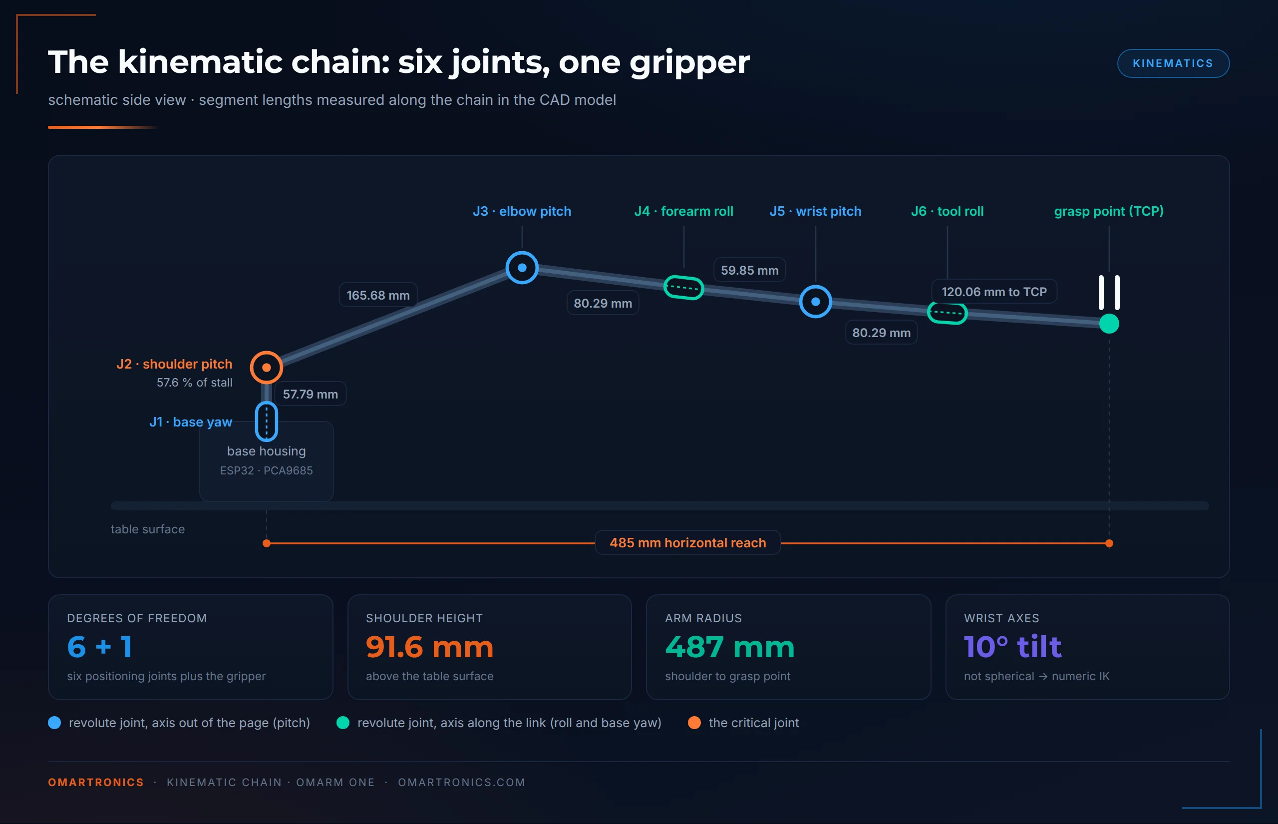
J1، انعراج القاعدة (Yaw). يدير الذراع بأكملها حول المحور الرأسي، من 0 إلى 180 درجة. لا تولّد الجاذبية عزمًا حول محور رأسي، لكن الذراع الممتدة تولّد عزم انقلاب يزداد مع مدى الوصول. ويتحمل محملٌ هذا العزم، كما يوضح القسم 5 ذلك.
J2، ميل الكتف (Pitch). يقع على ارتفاع 91.6 mm فوق الطاولة، وعلى بعد 57.79 mm من J1 على امتداد السلسلة. هذا المفصل يحمل الذراع. فكل ما بعده يؤثر عبر ذراع رافعة يصل طولها إلى نصف متر، ويؤكد التحليل أدناه أنه المفصل الحرج في الآلة.
J3، ميل المرفق (Pitch). على بعد 165.68 mm من الكتف، وهو طول الذراع العلوية. يحمل الساعد والمعصم والقابض.
J4، لف الساعد (Roll). بعد المرفق بمسافة 80.29 mm. يدير مجموعة المعصم بأكملها حول محور الساعد.
J5، ميل المعصم (Pitch). على مسافة 59.85 mm أخرى نحو الخارج. يُميل القابض إلى الأعلى وإلى الأسفل.
J6، لف الأداة (Roll). على مسافة 80.29 mm أخرى نحو الخارج. يدير القابض حول محوره.
القابض. فكّان متوازيان يُداران بالتروس، ونقطة الإمساك على بعد 120.06 mm من شفة الأداة (Tool flange، وهي سطح التثبيت في نهاية الذراع). كل أرقام مدى الوصول والحمولة في هذا المقال مذكورة عند نقطة الإمساك هذه.
محورا اللف مائلان بزاوية 10 درجات بالنسبة إلى الساعد؛ القسم 5 يشرح ما يكلفه ذلك.
معاملات Denavit-Hartenberg
جديد في عالم الروبوتات؟ تجاوز هذا الجدول. معاملات Denavit-Hartenberg (DH) مجموعة قياسية من أربعة أرقام لكل مفصل تصف هندسة الروبوت وصفًا كاملًا. وقد حُسب هذا الجدول من وصف الروبوت نفسه (URDF) الذي يعتمد عليه التوأم الرقمي في الجزء 2.
في الجدول، a هو طول الوصلة، وalpha هو الالتواء بين محاور المفاصل، وd هو الإزاحة على امتداد المحور السابق، وtheta هو متغير المفصل. والإزاحات في العمود الأخير هي الفرق بين صفر DH وصفر السيرفو؛ وهي موجودة لأن الذراع رُسمت أولًا ثم حُددت معاملاتها بعد ذلك. وهي لا تخرق F6: فزاوية CAD ما زالت تساوي زاوية السيرفو، وهذه الأرقام تربط تلك الزاوية المشتركة بصفر الاصطلاح نفسه فقط.
| i | a (mm) | alpha (درجة) | d (mm) | theta |
|---|---|---|---|---|
| 1 | 0.00 | −90.00 | 0.00 | q1 |
| 2 | 165.68 | 180.00 | −30.63 | q2 − 152.66° |
| 3 | 0.50 | −90.00 | −30.63 | q3 + 107.12° |
| 4 | 0.00 | −90.00 | 125.46 | q4 + 180.00° |
| 5 | 0.50 | −90.00 | 0.27 | q5 + 90.00° |
| 6 | 0.00 | 0.00 | 74.21 | q6 + 90.00° |
قيم 0.50 mm في العمود a حقيقية: يحتوي نموذج CAD على إزاحة جانبية مقدارها نصف مليمتر بين محاور الميل ومحاور اللف. ويضم العمود alpha مضاعفات صحيحة لـ 90 درجة رغم ميل محوري اللف بمقدار 10 درجات، لأن هذا الميل يقع في مستوى العمودي المشترك (Common normal، وهو الخط العمودي على محوري المفصلين كليهما). لذلك يدمجه الاصطلاح في الإزاحات بدلًا من الالتواء.
يُتحقق من الجدول تلقائيًا. يبني سكربت التحليل الحركيات الأمامية من هذه الصفوف ويطابقها مع ملف URDF عبر 2000 وضعية عشوائية. ويرفض طباعة أي جدول يقل مدى الوصول فيه عن القيمة المقيسة 485 mm.
تحليل عزم الدوران
بالنسبة إلى مفصل يحمل الذراع في مواجهة الجاذبية، فإن عزم الدوران الساكن في أسوأ حالة هو
tau = sum over all links beyond the joint of ( m_link * g * horizontal_distance_to_axis )
محسوبًا عند أسوأ وضعية يمكن توجيه ذلك المفصل إليها. في OmArm Zero أجريت هذا الحساب بأربع كتل مركزة وآلة حاسبة. أما OmArm One فلديه ستة مفاصل واثنا عشر جسمًا، لذا يمسح نموذج الكتل في CAD فضاء المفاصل بحثًا عن أسوأ حالة لكل مفصل.
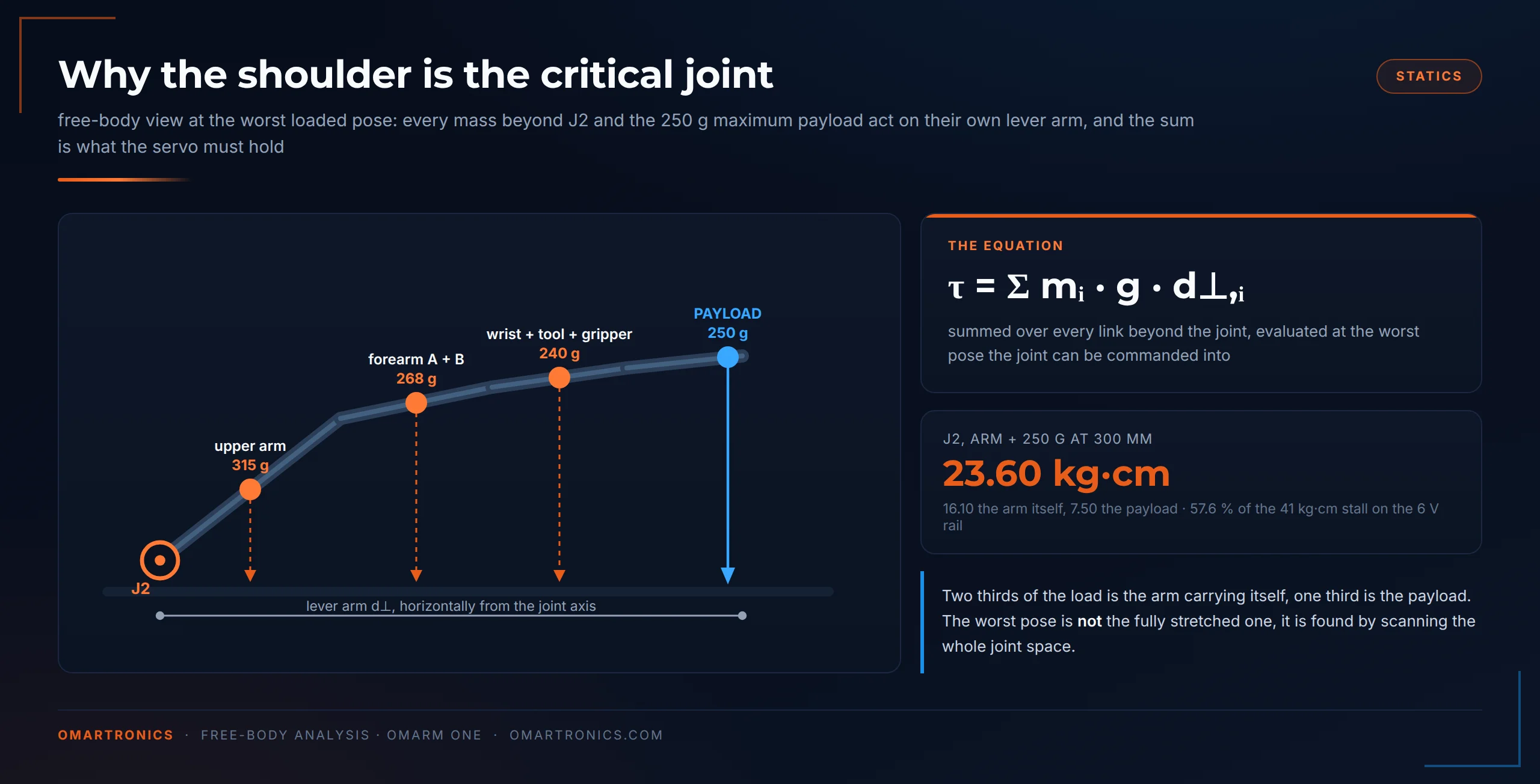
تأتي الكتل من مجسمات CAD، وفيها خطآن كبيران في اتجاهين متعاكسين. يعامل النموذج كل جزء مطبوع على أنه مادة مصمتة، بينما تتكون الأجزاء الحقيقية من غلاف وملء داخلي (جدران خارجية مصمتة حول داخل مجوف جزئيًا)، لذا فهو يبالغ في حساب البلاستيك. كما أنه لا يتضمن السيرفوهات ولا المحامل ولا البراغي ولا الأسلاك، فالعتاد غائب عنه. بعد التجميع وزنت الآلة الكاملة 1283 g على ميزان مطبخ، مقابل 1284 g للنموذج المصمت. ويأتي هذا التطابق من خطأين يلغي أحدهما الآخر: نحو 860 g من العتاد الذي يتجاهله النموذج (السيرفوهات، والمحامل، و86 قطعة تثبيت، واللوحات، والأسلاك) تحل محل البلاستيك الذي توفره طباعة الغلاف والملء الداخلي بشكل شبه تام. وعند إدخال الوزن في سكربت التحليل على أنه MEASURED، يخرج معامل التحجيم 0.999، وتتغير كل قيمة لعزم الدوران والحمولة أدناه بمقدار عُشر بالمئة.
يعطي هذا الجدول عزم الدوران الذي يحتاجه كل مفصل عندما تحمل الذراع الحد الأقصى المحدد في F1، أي 250 g على نصف قطر 300 mm، وهي حالة الحمل التي اختيرت المحركات على أساسها. ويُمسح كل مفصل في أسوأ وضعية له، والعمودان الأولان هما جزءا المجموع نفسه.
| المفصل | الذراع نفسها | الحمولة | M المطلوب (kg·cm) | عزم التوقف المطلوب، M/0.63 | ما يعنيه |
|---|---|---|---|---|---|
| J1 انعراج القاعدة | 0.00 | 0.00 | 0.00 | 0.0 | لا عزم من الجاذبية، لكن أكبر عزم انحناء على الذراع |
| J2 الكتف | 16.10 | 7.50 | 23.60 | 37.5 | المفصل الحرج، وهذا الصف يحدد مقاس السيرفو |
| J3 المرفق | 6.21 | 7.99 | 14.20 | 22.5 | ثاني أسوأ حالة، وحصة الحمولة هنا أكبر من حصة الذراع |
| J4 لف الساعد | 1.46 | 4.85 | 6.31 | 10.0 | الحمولة هي الغالبة من هنا فصاعدًا |
| J5 ميل المعصم | 1.46 | 4.85 | 6.31 | 10.0 | الأمر نفسه |
| J6 لف الأداة | 0.01 | 0.31 | 0.33 | 0.5 | يمكن إهماله؛ القسم 5 يعود إلى هذا الرقم |
أكبر متطلب على الذراع كلها هو 37.5 kg·cm، وهذا الرقم وحده يحدد فئة السيرفو وجهد خط التغذية معًا. يقدم DS3240 عزمًا قدره 36 kg·cm عند 5 V و41 kg·cm عند 6 V، لذا 6 V هو خط التغذية القياسي في هذه الذراع، لأن الحد الأقصى البالغ 250 g يحتاج إليه. وعند 5 V تظل الذراع تلبي الحالة الاسمية البالغة 200 g، التي تتطلب 35.1.
نقطتان أخريان من ذلك الجدول. تنقلب نسبة الذراع إلى الحمولة على امتداد السلسلة، من 68 بالمئة للهيكل عند الكتف إلى 23 بالمئة عند مفاصل منتصف الذراع. لذلك يضيف ساعدٌ أخف وزنًا حمولةً أكثر مما يضيفه سيرفو أكبر. كما يحتاج الكتف إلى 23.60 kg·cm بينما يحتاج المرفق إلى 14.20، فمفصل واحد يحدد الآلة كلها.
للتحقق من أن النموذج متحفظ، أعدت حساب عزم الكتف من المكونات.
- الهيكل المطبوع بعد J2: 248 g، محسوبًا من PLA بكثافة 1.24 g/cm3 ونسبة ملء 24 بالمئة معايَرة على وزن 421 g الذي قاسه برنامج التقطيع.
- العتاد الذي لا يتضمنه النموذج: خمسة DS3240 بوزن 58 g لكل منها وSG90، في المفاصل التي تُركَّب فيها، حتى مسافة 365 mm. يضاف إليها ثلاثة محامل 695ZZ بوزن 2.31 g، ومحاور M5 الثلاثة، و40 برغيًا، وخمسة أذرع سيرفو (Horn)، وثماني حشوات نحاسية، والنابض، و1.6 m من كابل السيرفو. والمجموع 419 g.
- النتيجة: 15.13 kg·cm مقابل 16.10 في النموذج لحالة الحمل نفسها.
يغطي هذا الحساب التفصيلي 1199 g من وزن الذراع الموزونة. وحتى لو كان كل غرام غير محسوب واقعًا بعد الكتف، فإن العزم يبقى عند قيمة النموذج أو دونها. لذلك فإن النموذج لا يقدّر القيم بأقل من الواقع أبدًا، والقيمة 23.60 kg·cm حدٌّ أعلى.
اشتقاق الحمولة: من أين تأتي قيمتا 200 g و250 g
عند عزم التوقف يتوقف المحرك تمامًا ويسحب أقصى تيار لديه، وهو 3.1 A عند 5 V في DS3240. والسيرفو الذي يبقى قريبًا من التوقف ترتفع حرارته بشدة خلال دقائق، لذا لا تُحدَّد الحمولة أبدًا على أساس عزم التوقف. وقد حددت الاختبارات على OmArm Zero السقف عند 63 بالمئة من عزم التوقف للحمل المستمر، وتنتقل هذه القاعدة إلى هنا دون تغيير.
بعد ذلك تُستخرج الحمولة وضعيةً بوضعية. خذ احتياطي عزم الدوران المتبقي عند كل مفصل واقسمه على ذراع رافعة الحمولة حول ذلك المفصل. وأصغر نتيجة بين المفاصل الستة كلها تحدد ما تستطيع الذراع حمله في تلك الوضعية. كرر ذلك عبر مساحة العمل، فتحصل على مواصفات الحمولة في صورتها المفيدة: جدول بحسب نصف قطر العمل.
| نصف قطر العمل | 6 V مستمر | 6 V عند التوقف | 5 V مستمر | 5 V عند التوقف |
|---|---|---|---|---|
| 250 mm | 407 g | 1013 g | 281 g | 813 g |
| 300 mm، المتطلب F1 | 325 g | 830 g | 219 g | 664 g |
| 303 mm (مدى الوصول الكامل لـ OmArm Zero) | 321 g | 821 g | 217 g | 656 g |
| 350 mm | 268 g | 701 g | 178 g | 558 g |
| 370 mm، الحد الأقصى 250 g | 252 g | 661 g | 167 g | 526 g |
| 400 mm | 225 g | 605 g | 146 g | 480 g |
| 435 mm، الحمولة الاسمية 200 g | 202 g | 551 g | 129 g | 436 g |
| 485 mm (امتداد كامل) | 175 g | 488 g | 110 g | 385 g |
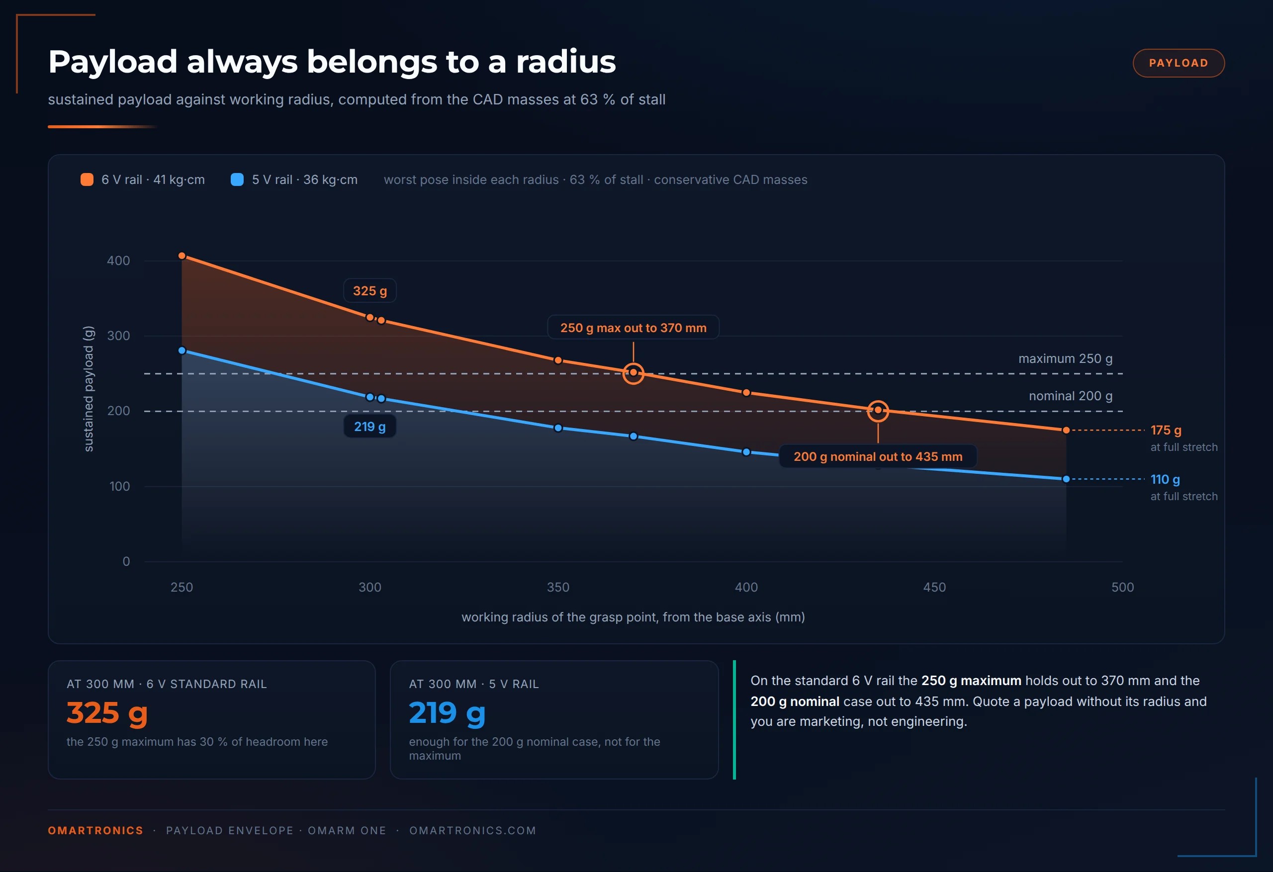
أعمدة 6 V هي المعتمدة. أما أعمدة 5 V فموجودة لأن كثيرًا من طاولات العمل تحتوي على مزود طاقة 5 V، وهي تبين ثمن ذلك. ينخفض عزم السيرفو نفسه من 41 إلى 36 kg·cm، وعند 300 mm ينخفض الحد الممكن من 325 g إلى 219 g. وهذا يكفي للحالة الاسمية البالغة 200 g، لكنه لا يكفي للحد الأقصى البالغ 250 g.
يتحقق المتطلب F1 بهامش مريح. عند نصف قطر عمل 300 mm تتحمل الذراع 325 g بشكل مستمر على خط التغذية القياسي. وحمل الحد الأقصى البالغ 250 g هناك يرفع حمل أسوأ مفصل إلى 57.6 بالمئة من عزم التوقف، أي دون خط 63 بالمئة. ومفصل J2 هو المفصل المقيِّد في كل وضعية محمَّلة. وعند مسح كل مفصل في أسوأ وضعية محمَّلة له مع الحد الأقصى، يأتي J3 ثانيًا بنسبة 34.6 بالمئة، ويصل مفصلا منتصف الذراع إلى 15.4، ويبقى لف الأداة دون 1. ينتهي الحد الأقصى البالغ 250 g عند 370 mm، والحالة الاسمية البالغة 200 g عند 435 mm. ونصفا القطر هذان هما حد المواصفات؛ وكل ما يتجاوزهما يقع ضمن الصفوف الأخف في الجدول.
يجيب الجدول نفسه عن سؤالين كانا لدي بشأن Zero. فعند مدى الوصول الكامل لـZero البالغ 303 mm تتحمل هذه الذراع 321 g، بينما لم تتحمل Zero سوى 150 g، أي أكثر من ضعف الحمولة عند نصف القطر نفسه. كما تبقى الحمولة القصوى لـZero البالغة 150 g متاحة إلى ما بعد 485 mm، أي أبعد مما كانت Zero تستطيع الوصول إليه أصلًا.
أعمدة التوقف موجودة لتوضيح الصورة فقط. فعند نصف قطر 300 mm ينفد عزم الذراع تمامًا عند 830 g، وهو الحد المطلق لهذه الهندسة. والحمولات القريبة من هذه القيمة ستتطلب إعادة تصميم.
مساحة العمل ومدى الوصول
تصل نقطة الإمساك إلى 485 mm أفقيًا من محور القاعدة، وإلى 487 mm مقيسةً من الكتف، الذي يقع على ارتفاع 91.6 mm فوق الطاولة وعلى بعد 30.63 mm من محور القاعدة. ولأن J1 يمسح من 0 إلى 180 درجة لا دائرة كاملة، فإن مساحة العمل نصف قشرة متجهة إلى الأمام نصف قطرها الخارجي نحو 487 mm.

مقارنةً بـ OmArm Zero: مدى وصول من 303 إلى 485 mm، أي أكثر بـ 60 بالمئة، ولأن الحجم يتناسب مع مكعب هذه النسبة، فالمساحة القابلة للوصول أكبر بنحو أربعة أضعاف. ومساحة العمل المتجهة إلى الأمام تمنح الكاميرا في الجزأين 4 و5 مشهدًا واحدًا نظيفًا تصل إليه الذراع دائمًا من جهة معروفة. كما أن الدائرة الكاملة ستتطلب حلقات انزلاق (Slip rings) أو ترتيبًا خاصًا لكابلات السيرفو السبعة.
ميزانية الطاقة
سبعة سيرفوهات على خط تغذية واحد بجهد 6 V. من ورقة بيانات DS3240: تيار خمول 4 mA لكل سيرفو مفصل، وتيار توقف 3.1 A عند 5 V؛ القسم 6 يقدّر بالاستيفاء نحو 3.54 A عند 6 V.
| الحالة | التيار |
|---|---|
| خمول، دون حمل على المفاصل | 24 mA إضافةً إلى الإلكترونيات |
| حركة منسقة نموذجية | نحو 4.3 A |
| أسوأ حالة: ستة مفاصل متوقفة إضافةً إلى القابض | 19.3 A |
الصفوف الثلاثة كلها مبنية على قيم ورقة البيانات عند 5 V المذكورة أعلاه. والصف النموذجي هو تقدير سكربت التحليل: مفصلان قرب نصف تيار التوقف، وأربعة بتيار 0.25 A لكل منها، والقابض عند 30 بالمئة من تيار توقفه. وعلى خط التغذية 6 V ترفع القيمة المستوفاة 3.54 A لكل مفصل أسوأ حالة إلى نحو 22 A (6 × 3.54 A إضافةً إلى SG90).
مزود طاقة 6 V بتيار 10 A يغطي كل الحالات الواقعية. فقيمة أسوأ حالة تتطلب أن تُعاق المفاصل الستة كلها ميكانيكيًا في الوقت نفسه، وهذا لا يحدث إلا عند الاصطدام، ومهمة البرنامج الثابت ألا يترك السيرفوهات في تلك الحالة أبدًا. ويتحمل مكثف كهروليتي بسعة من 1000 إلى 2200 ميكروفاراد موصول على خط التغذية التغيراتِ العابرة عند بدء التشغيل وتغيير الاتجاه.
في جانب التغذية قاعدتان لا أتهاون فيهما. خط التغذية 6 V، وهو السقف الذي يفرضه قابض SG90؛ القسم 6 يعرض الموازنة كاملة. ولا تأتي تغذية السيرفو أبدًا من طرف USB في ESP32. فمصدر USB الذي يغذي هذا الطرف لا يقدم إلا جزءًا صغيرًا من تيار توقف سيرفو واحد، وتحميله فوق طاقته قد يتلف اللوحة أو منفذ USB في الحاسوب.
وقاعدة ثالثة تعلمتها بالتجربة أثناء هذا البناء: تحقق من جهد خط التغذية مرتين قبل أن توصل أي شيء. فقد غذيت خط السيرفو مرة بجهد 8 فولت من مزود طاقة مخبري كان لا يزال مضبوطًا على المشروع السابق. فارتعشت الذراع من تلقاء نفسها، وسخن ESP32 إلى درجة مقلقة، وأغلق حاسوبي منفذ USB لحماية نفسه. نجا كل شيء. فمزود الطاقة القابل للضبط يحتفظ بإعدادات آخر استخدام له؛ اضبطه، واقرأ الشاشة، ثم وصّل الذراع بعد ذلك فقط.
5. التصميم الميكانيكي ونموذج CAD

رُسم OmArm One في Autodesk Inventor، وهو برنامج CAD الذي أعمل به أسرع من غيره. كل ما في هذا المقال مستخرج من ذلك التجميع الواحد: الرسوم المتحركة المفككة (Exploded) في القسم 7، والرسم الهندسي بأرقام الإشارة (Balloons) في القسم 6، وملفات STL على لوحَي الطباعة كليهما. وينقل الجزء 2 هذه الهندسة إلى Fusion 360، الذي يبني مُصدِّر URDF فيه التوأم الرقمي، لذا يجب أن يُصدَّر كل جزء دون أخطاء.
ثمانية عشر جسمًا مطبوعًا من PLA، وسبعة سيرفوهات، وستة محامل كروية. وكانت التعليمات لكل جزء واحدة:
- ضع المادة حيث يمر مسار الحمل.
- دع السيرفو يقدم عزم الدوران ولا شيء غيره.
- لا تعتمد أبدًا على التصاق الطبقات لتماسك الآلة.


القاعدة
تؤدي القاعدة ثلاث مهام في الوقت نفسه: تدير الذراع، وتحمل وزنها، وتقاوم عزم انقلابها. في OmArm Zero كان ذراع سيرفو (Horn) واحد يؤدي المهام الثلاث كلها. أما هنا فقد فُصلت هذه المهام عن بعضها.
تستقر المنصة الدوارة على محمل دفعي محوري 51110، بأبعاد 50 x 70 x 14 mm، وهو حلقة مسطحة من الكرات داخل قفص تدور بين حلقتين مقسّاتين. صُممت المحامل الدفعية لحمل واحد: ضغط إلى الأسفل مباشرة على امتداد المحور. فوزن الذراع كله، مع ما تحمله، يمر عبر هذه الحلقة إلى هيكل القاعدة. كما تحدد الحلقة ارتفاع المنصة وتثبتها عنده أثناء دورانها.
وداخل تلك الحلقة يوجد محمل كروي شعاعي 6806ZZ، بأبعاد 30 x 42 x 7 mm، ملتفًّا حول صُرّة المنصة الدوارة. تتحمل المحامل الشعاعية الأحمال العمودية على المحور، وهي هنا مركّبة الانقلاب. فالذراع الممتدة حتى 485 mm تحاول أن تدفع المنصة جانبيًا كأنها رافعة. ولأن المحمل 6806 محمل رقيق المقطع (حلقاته رقيقة مقارنةً بقطره) وقطره الخارجي كبير يبلغ 42 mm، فإنه يقاوم الميلان على قاعدة عريضة، فتبقى المنصة مستوية.
ما يبقى للسيرفو هو الدوران وحده. يُثبَّت ذراع السيرفو (Horn) بصُرّة المنصة بأربعة براغٍ، والحمل الوحيد الذي يصل إلى مجموعة التروس هو عزم الدوران اللازم لتدوير الذراع. وتمنح حلقة المحمل الدفعي بقطر 70 mm المنصةَ دائرة ارتكاز يزيد عرضها على ثلاثة أضعاف عرض ذراع السيرفو (نحو 20 mm).



هيكل القاعدة هو أيضًا صندوق الإلكترونيات. تُركَّب اللوحتان على الجدار الداخلي، ويقع المفتاح ومقبس الطاقة الأسطواني (Barrel Jack) في الوجه الخارجي، وفي السطح العلوي فتحات تهوية فوق لوحة القيادة. لهذا تتكون القاعدة من صندوق تعلوه أسطوانة، ولهذا لا يخرج من الذراع المكتملة سوى كابل واحد.
مفاصل الإمالة (Pitch): ترتيب المحمل الثابت والمحمل الحر في J2 وJ3 وJ5
تتحمل مفاصل الإمالة الثلاثة أحمال الانحناء أثناء دورانها. وتستخدم المفاصل الثلاثة الترتيب نفسه، الذي يسميه مهندسو الميكانيكا ترتيب المحمل الثابت والحر (Fixed-Loose) (محمل مُحدِّد للموضع ومحمل غير مُحدِّد له). يُثبَّت أحد جانبي العمود تثبيتًا صلبًا، أما الجانب الآخر فمدعوم لكنه حر في الحركة جزءًا من المليمتر على امتداد المحور.
عمليًا، كل مفصل إمالة هو شوكة مطبوعة تحيط بالوصلة التالية من جانبيها:
- الجانب الثابت هو السيرفو وذراعه (Horn). يُثبَّت ذراع السيرفو 25T (25T: محزّز بـ 25 سنًّا، وهو المعيار السائد فعليًا في محركات السيرفو من هذه الفئة) بالبراغي في أحد فرعي الشوكة. ويستقر جسم السيرفو في القطعة المقابلة، فيُدار المفصل عبر المحزّز. ينقل هذا الجانب عزم الدوران ويحدد موضع المفصل على امتداد المحور. وتتغير القطعة التي تحمل جسم السيرفو على طول الذراع. ففي الكتف والمرفق يستقر السيرفوان كلاهما في الذراع العلوية، ويُثبَّت ذراعاهما بالبراغي متجهَين منها إلى الخارج. لذلك تُركِّب في الخطوة 5 سيرفوين على هذه الوصلة الواحدة قبل تركيبها على بقية الذراع.
- الجانب الحر هو محمل كروي مصغّر 695ZZ، مقاس 5 x 13 x 4 mm، مثبَّتًا بالضغط في فرع الشوكة المقابل. يمر مسمار ملولب M5 عبر الحلقة الداخلية للمحمل مع جلبة مطبوعة تعمل كمباعد، وتشدّ صامولة M5 هذه المجموعة على الوصلة. وهكذا تدور الوصلة على محمل، وتكون الشوكة مدعومة من الجانبين.
لماذا لا نستخدم محملين ثابتين؟ لأن دعامتين صلبتين على عمود واحد تتعارضان. فالقطع المطبوعة تتغير أبعادها مع الحرارة والرطوبة، وتفاوت الطباعة على عرض شوكة يبلغ 60 mm يصل إلى بضعة أعشار المليمتر. وإذا ثُبِّت الجانبان كلاهما، ينتهي الأمر بالعمود محمَّلًا بإجهاد مسبق لم يصممه أحد. فيتعسّر دورانه، ويعمل السيرفو ضده، وتخسر في الاحتكاك جزءًا من عزم الدوران كان ينبغي أن يذهب إلى الحمولة. أما ترتيب المحمل الثابت والحر فيتحمل الانحناء من الجانبين ويترك الطول المحوري حرًا. وتستخدم أعمدة الدوران في آلات التشغيل (Spindles) المبدأ نفسه عادةً.

الجلبة هي القطعة الأكثر عرضة للارتجال السيئ. فطولها يحدد مقدار إحكام شدّ الشوكة على الوصلة. إذا كانت أقصر من اللازم انسحب فرعا الشوكة إلى الداخل حتى يتصلّب المفصل؛ وإذا كانت أطول من اللازم تقلقلت الوصلة. اطبعها أو اخرطها بالطول المحدد في نموذج CAD، فتحصل على مفصل يدور بحرية تحت وزنه الذاتي دون أي خلوص جانبي يمكن قياسه. الجلبتان كلتاهما قطعتان مطبوعتان: القطر الخارجي Ø 8.9 mm، وقطر الثقب 5.2 mm، والطول 9.0 mm في الكتف (sleeve_1) و8.0 mm في مفصلي الإمالة الآخرين (sleeve_2). اطبعهما في وضع أفقي حتى يبقى الثقب دائريًا، أو اخرطهما من الألومنيوم إن كانت لديك مخرطة وأردت أن تكون أوجه الشد متعامدة تمامًا.
نابض الكتف
يوجد نابض شدّ عند الكتف، مركَّب بين نتوءين مطبوعين، أحدهما على منصة القاعدة الدوارة والآخر على الذراع العلوية، ويمر مسمار (Pin) عبر كل طرف معقوف منه.
كان لدى Zero نابض أيضًا، لكنه أدى هناك مهمة مختلفة: كان سيرفو الكتف يعمل عند حدود فئته، وكان النابض يُبقي الذراع ضمن ميزانية عزم الدوران. أما في One فالنابض لا يضيف إلا احتياطيًا: حمل أقل على السيرفو، وحرارة أقل عند الثبات الطويل في وضع واحد، وتيار أقل عند الامتداد الكامل. كما يخفف من حدة السقوط إذا انقطعت الطاقة عن السيرفو والذراع ممدودة. كل أرقام عزم الدوران والحمولة في القسم 4 حُسبت دون النابض، ومع ذلك لا يتجاوز حمل الكتف 57.6 بالمئة من عزم التوقف مع الحمولة القصوى 250 g بين فكّي القابض.
قستُ النابض بميزان أمتعة ومسطرة فولاذية. في وضع السكون كان طرف النابض عند علامة 30 mm وقرأ الميزان صفرًا. وعند سحبه حتى علامة 60 mm، أي باستطالة 30 mm، قرأ الميزان 1.33 kg.
أي 13.05 نيوتن عند استطالة 30 mm، والقيمة 13 N عند 30 mm هي الرقم الذي تعتمد عليه عند الشراء.
تحويل ذلك إلى ثابت النابض (Spring Rate) يتطلب خطوة إضافية يسهل الخطأ فيها. تُلَفّ نوابض الشد مع شدّ ابتدائي: تكون اللفات مضغوطة بعضها على بعض، ولا يبدأ النابض بالانفتاح حتى تتجاوز قوة تحميل مسبق F0. لذلك يكون خط الحمل F = F0 + k·s، وليس F = k·s. إذا قسمت 13.05 N على 30 mm تحصل على 0.435 N/mm، لكن هذه القيمة يختلط بها التحميل المسبق، ما يجعلها حدًا أعلى. أما الثابت الحقيقي فيقع بين 0.33 و0.44 N/mm بحسب التحميل المسبق. وأقرب نابض وجدته في الكتالوجات هو Gutekunst Z-071I: سلك بقطر 0.8 mm، وقطر خارجي 8.8 mm، وطول الجسم 32.3 mm دون الخطافين، و39.5 mm من ثقب إلى ثقب. ويذكر المصنّع ثابتًا قدره 0.333 N/mm مع شدّ ابتدائي قدره 1.55 N. وهذا يعطي 11.5 N عند 30 mm، أي بفارق لا يتجاوز 12 بالمئة عن النابض المركّب على ذراعي. إنه مرجع للمواصفات، وليس رابط شراء.
إذا أردت الثابت الدقيق، فخذ قراءتين تحت الحمل: اسحب حتى استطالة 15 mm وسجّل القوة، ثم اسحب حتى 30 mm وسجّلها مجددًا. يُلغى التحميل المسبق عند طرح القراءتين فتحصل على k مباشرة. القياس الكامل والحسابات والمقارنة مع الكتالوج موجودة في analysis/spring-rate-measurement.md في المستودع.
شراء بديل. اختر النابض بحسب القوة والطول المقيسين؛ فنابضان متشابهان في الشكل قد يختلفان كثيرًا في الثابت. يجب أن يسحب النابض بقوة من 11 إلى 15 نيوتن عند استطالة 30 mm وأن يبلغ طوله من 38 إلى 42 mm من ثقب إلى ثقب في وضع السكون. ويحتاج إلى خطافين يتسعان للمسمار (Pin) ومشوار استطالة قابل للاستخدام لا يقل عن 35 mm. قطر السلك بين 0.8 و1.0 mm تقريبًا، والقطر الخارجي من 8.5 إلى 10 mm. التفاوت المسموح واسع لأن هذا النابض مجرد هامش احتياطي: النابض الأليَن بنسبة 20 بالمئة يكلّفك قليلًا من المساعدة لا أكثر. تجنّب نابضًا يبدو مطابقًا لكنه أصلب بمرتين. فهذه النوابض موجودة بالقطر الخارجي نفسه 9 mm وبسماكة السلك نفسها، لكن بعدد لفات أقل، والنابض بهذه الصلابة يقاوم السيرفو أثناء نزول الذراع.
يبقى النابض في التجميع النهائي. ويمر خط تأثيره على بعد نحو 36 mm من محور J2، مقيسًا من المسقط الأمامي في نموذج CAD بمقياس المنصة. لذلك تقابل القوة المقيسة 13 N ما يقارب 4.8 kg·cm من التخفيف عند الكتف. أما مقدار ما يبقى منه عبر مدى حركة المفصل فمسألة أخرى، لأن المساعدة تتغير مع زاوية الكتف ولم أقِس هذا المنحنى. ولهذا السبب فإن أرقام عزم الدوران في القسم 4 لا تتضمنه.

مفاصل اللف (Roll): J4 وJ6
مفصلا اللف متحدا المحور، ولا شوكة فيهما. يدير السيرفو الجزء التالي من الذراع حول محوره الذاتي، لذا يختلف مسار الحمل: يبقى عزم الانحناء في معظمه داخل هذا الجزء.
J4، مفصل لف الساعد، يُضاف إليه محمل شعاعي 6806ZZ إلى جانب ذراع السيرفو. فهو يقع بعيدًا بما يكفي لأن يولّد المعصم والقابض حوله عزم انحناء حقيقيًا. يتحمل المحمل حمل الانحناء، ولا يقدّم السيرفو سوى عزم الدوران حول محور اللف.
J6، مفصل لف الأداة، صُمِّم في الرسم ليُركَّب فيه المحمل نفسه 6806ZZ، لكنه في التصميم بصيغته الحالية يعمل على ذراع السيرفو وحده. يحمل J6 القابض والحمولة فقط. ويبلغ عزم الدوران حول محور اللف 0.33 kg·cm عند الحمولة القصوى 250 g (و0.01 kg·cm من الذراع نفسها). أما عزم الانحناء على عمود الخرج فيبلغ نحو عشرة أضعاف ذلك. فعندما يكون محور اللف أفقيًا، تولّد الـ 250 g عند نقطة الإمساك، على بعد 120 mm، عزمًا قدره 3.0 kg·cm، ويضيف القابض نفسه نحو 0.3. هذا هو الرقم الذي يسأل عنه F4. في الذراع المجمّعة يتحمله عمود الخرج في السيرفو المركّب على محملين. ويبقى مقعد المحمل في نموذج CAD تحسّبًا لمن يعلّق أداة أثقل على الشفة (Flange).
المعصم المائل وثمنه
ينحرف محورا اللف، J4 وJ6، بمقدار 10 درجات عن خط منتصف الساعد. والمعصم الذي لا تلتقي محاوره الثلاثة في نقطة واحدة ليس معصمًا كرويًا، ومن دون معصم كروي لا يوجد حل تحليلي مغلق للحركيات العكسية كما في الكتب الدراسية. لذا يجب حل كل وضعية عدديًا.
في عرض كلاسيكي للروبوتات يُعدّ هذا عيبًا. أما في هذه السلسلة فلا يكلّف شيئًا، لأن الجزء 3 يسلّم الذراع إلى MoveIt 2، الذي يحل الحركيات العكسية عدديًا في كل الأحوال ولا يسأل أبدًا إن كان معصمك كرويًا. أفضّل أن أحتفظ بالهندسة التي تطلبتها الميكانيكا على أن أشوّه الميكانيكا لإرضاء أداة حل لن أستخدمها.
الميلان سببه ترتيب المكونات داخل الحيز المتاح، والرسم المقطعي يوضح ذلك. تستقر سيرفوات اللف داخل أجزائها، وجعل محور الخرج على استقامة الساعد كان سيكلّف إما جزءًا أسمك وإما حاوية سيرفو بارزة خارج الحيز المحدد. ومحور اللف يتبع السيرفو، ولذلك يرث ميلان الـ 10 درجات.
تجميع القابض
يحتفظ القابض بفكرة Zero: سيرفو واحد يدير زوجًا من التروس، وزوج التروس يحرّك فكّين، وينغلق الفكّان بشكل متماثل نحو خط المنتصف. للفكّين المتوازيين أهمية لأن الجسم الذي يُدفع جانبيًا أثناء الإمساك ينتهي به الأمر في مكان لم تتوقعه الكاميرا، والجزآن 4 و5 يعتمدان على ألّا يحدث ذلك.
تُركَّب ثماني قطع مطبوعة على قاعدة القابض: ترسان، وأربع أذرع وصل، وفكّان، وتُثبَّت الأذرع عند طرفيها ببراغي M3. وتقع نقطة الإمساك على بعد 120.06 mm من شفة الأداة.

ثلاثة تغييرات مقارنةً بقابض Zero:
- تدور مفاصل أذرع الوصل على براغٍ مثبتة في حشوات ملولبة M3، ما ينهي الارتخاء الذاتي البطيء الذي ظهر في فك Zero ويزيل الخلوص من آلية الوصل.
- أصبح زوج التروس أعرض، فتبقى الأسنان معشّقة بالكامل تحت الحمل.
- يلتقي القابض بشفة الأداة عبر دائرة تثبيت ذات أربعة ثقوب، فيمكن تركيب قابض مختلف، أو أداة مختلفة تمامًا، على الذراع دون المساس بالمعصم.
التصميم من أجل التصنيع
تُطبع كل القطع من PLA على طابعة Bambu Lab P1S، موزعةً على لوحتي طباعة.
يحرّك النموذج الحركي اثني عشر جسمًا، مسماة كما في ملف URDF من دون اللاحقة _1 التي يضيفها المُصدِّر في الجزء 2 (الجدول أدناه). أما المجموعة المطبوعة فتضم أكثر من ذلك: 23 قطعة من 18 جسمًا مختلفًا، وكلها مدرجة في القسم 6. وتُطبع أيضًا الجلبات، ومسمارا النابض، وأذرع الوصل الأربع للفكّين، وغطاءان؛ وهي غير موجودة هنا لأنه لا شيء في النموذج يدور حولها.
| الجسم في النموذج | الكمية | الدور |
|---|---|---|
| base_link | 1 | هيكل القاعدة: تجويف السيرفو، ومقاعد المحامل، وحجرة الإلكترونيات |
| base_link_upper | 1 | المنصة الدوارة فوق المحامل، وتحمل شوكة الكتف |
| link_1 | 1 | الذراع العلوية، من الكتف إلى المرفق |
| link_2 | 1 | جزء الساعد، من المرفق إلى مفصل لف الساعد |
| link_3 | 1 | جزء الساعد، من مفصل لف الساعد إلى مفصل إمالة المعصم |
| link_4 | 1 | جزء المعصم، من مفصل إمالة المعصم إلى مفصل لف الأداة |
| tool_link | 1 | شفة الأداة، وتحمل القابض |
| gripper_base | 1 | هيكل القابض |
| gripper_gear | 2 | زوج تروس، أحدهما قائد والآخر منقاد |
| gripper_finger | 2 | فكّان متوازيان |
| الإجمالي | 12 |
تختلف هذه الطباعة عن مهمة الطباعة المعتادة في ثلاث نقاط. يجب أن تُطبع مقاعد المحامل بمقاسها الدقيق: فالمقعد الأصغر من اللازم لن يتسع لمحمله، والمقعد الذي يُطبع أكبر بمقدار 0.3 mm يترك المحمل يدور داخله. أجرِ اختبار أبعاد قبل أن تطبع القاعدة؛ الخطوة 3 في القسم 7 تتضمن الفحص بالقدمة (Caliper). وتحتاج فروع الشوكة إلى عدد كافٍ من الجدران المحيطية (Perimeters، وهي الجدران الخارجية المصمتة لكل طبقة) لتبقى صلبة، لأن الشوكة التي تنثني تُضيّع فائدة المحمل الحر. كما يجب أن يجعل اتجاه طباعة وصلات الذراع خطوطَ الطبقات ممتدة على طول الوصلة، فيسري حمل الانحناء على امتداد المادة بدلًا من أن يفصل طبقاتها.
الأرقام أدناه مأخوذة من مشروع Bambu Studio الخاص بهذه الذراع. تُطبع اللوحتان كلتاهما بخيط Generic PLA على طابعة P1S بفوهة 0.4 mm. وقد جرى تقطيعهما باستخدام ملف الإعدادات الافتراضي 0.20 mm Standard @BBL X1C ، مع أن الطابعة من طراز P1S.
| لوحة الطباعة | خيط النموذج | الدعامات | الإجمالي | مدة الطباعة |
|---|---|---|---|---|
| 1، القطع الكبيرة | 85.77 m / 255.81 g | 7.69 m / 22.94 g | 93.46 m / 278.75 g | 9 h 07 min |
| 2، القطع الصغيرة | 55.40 m / 165.22 g | 1.55 m / 4.63 g | 56.95 m / 169.85 g | 5 h 59 min |
| 421.03 g | 27.57 g | 448.60 g | 15 h 06 min |
إعدادان ينبغي نسخهما. الدعامات شجرية، بنمط Tree Slim، وزاوية العتبة 45°، مع تفعيل الخيارين support critical regions only وremove small overhangs. يُبقي ذلك الدعامات الشجرية خارج ثقوب المحامل وتجاويف السيرفو. أما مسافة Z العلوية (Top Z distance) فهي 0.2 mm، أي طبقة واحدة بالضبط، فتنفصل الأوجه المدعومة بشكل نظيف. خيار الطوف (Raft) معطّل، وتُطبع الطبقة الأولى بكثافة 90 بالمئة.
مشروع Bambu Studio الذي يضم اللوحتين (OmArm-One_print-plates.3mf) موجود في الحزمة، لذا يمكنك إعادة توزيع القطع على اللوحتين كما هو موضح أعلاه بالضبط.

اعتمادًا على ملف URDF وحده، قدّر سكربت التحليل كتلة الذراع المكتملة بين 0.85 و1.05 kg، مقابل 1.284 kg في النموذج المصمت. ومع توفر كتلة القطع المطبوعة من برنامج التقطيع، يحل محل ذلك التقدير حسابٌ تجميعي لكتل المكونات.
| الكتلة | المصدر | |
|---|---|---|
| القطع المطبوعة | 421 g | برنامج التقطيع، خيط النموذج فقط |
| محركات السيرفو | 357 g | 6 × 58 g من DS3240 إضافةً إلى SG90 بوزن 9 g، وفق مواصفات المورّد |
| المحامل | 221 g | 51110 بوزن 160 g، واثنان من 6806ZZ بوزن 27 g، وثلاثة من 695ZZ بوزن 2.31 g، وفق الكتالوج |
| أدوات التثبيت، وأذرع السيرفو، والحشوات الملولبة، والنابض، واللوحات، والأسلاك | ~200 g | مفصّلة من قائمة القطع |
| ~1.20 kg |
تقل الكتلة المجمّعة بنحو 6.5 بالمئة عن كتلة الذراع الموزونة، والفارق قطع معدنية صغيرة غير مدرجة في القاعدة. أما أرقام الحمولة في القسم 4 فتبقى متحفظة في كلتا الحالتين، لأنها حُسبت باستخدام النموذج الأثقل.

6. قائمة المواد (BOM) واختيار المكونات
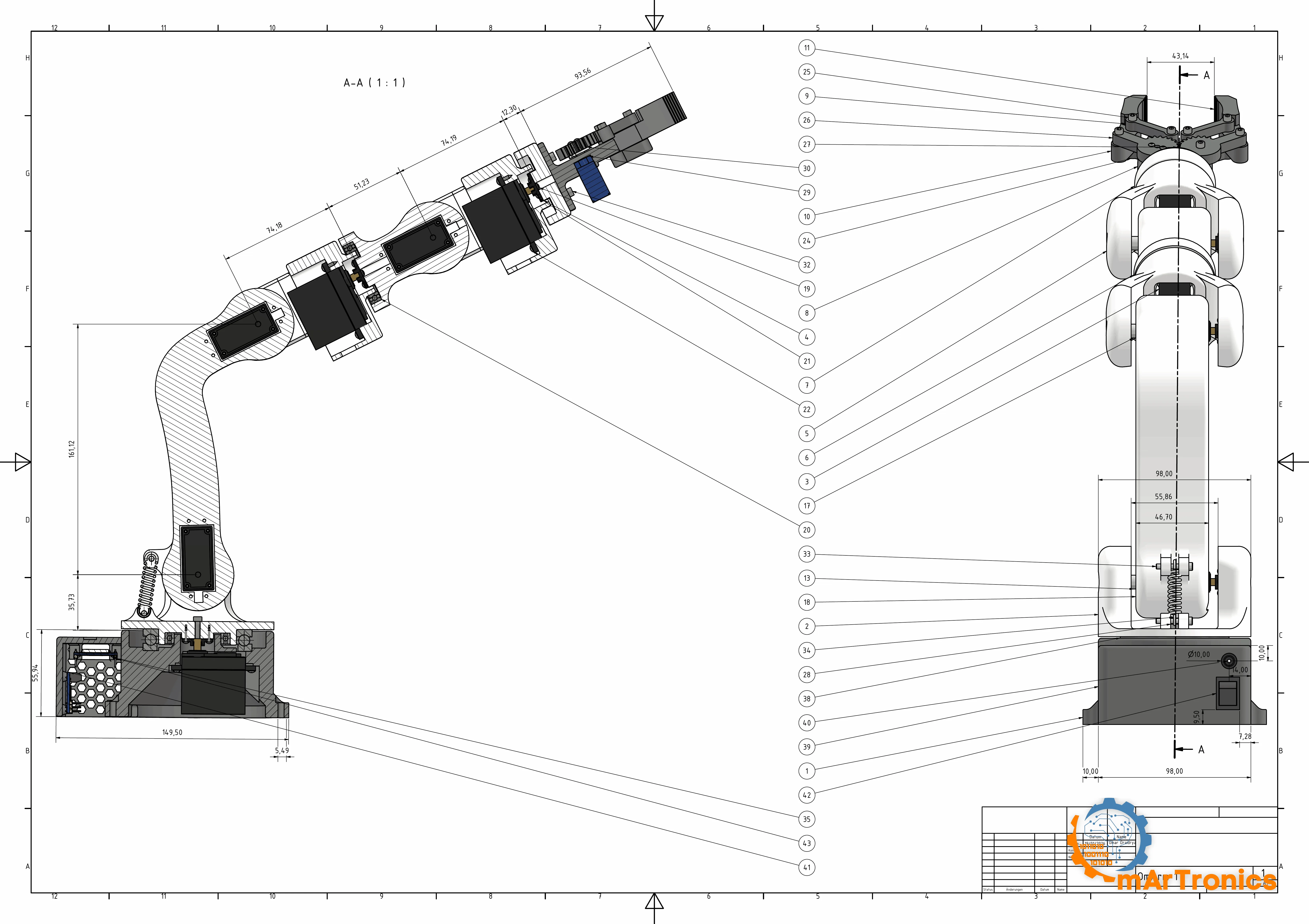
قائمة القطع الكاملة
العمود الأول هو رقم الفقاعة (Balloon) في الرسم أعلاه، مأخوذ من تجميع Inventor. الأرقام ليست متسلسلة، لأن Inventor يرقّم الأجزاء بترتيب دخولها إلى التجميع، ولم أُعِد ترقيمها. اختر فقاعة في الرسم، ثم ابحث عن صفها في الجدول. الموضع 23 غير موجود: يُدرجه التصدير على شكل خمسة عشر إدخالًا باسم “Document”، وهي سجلات داخلية في Inventor لا يقابلها أي جزء مادي.
الأسعار في جدول المتجر أدناه هي أسعار السوق كما في أغسطس 2026، مقرّبة ومُعلَّمة على أنها تقريبية. إنها ما تكلّفه القطع إذا طلبتها اليوم، لا ما كلّفني بنائي أنا. فقد تجمّعت قطع ذراعي على مدى أشهر ومن صندوقين من بقايا القطع، لذا فإن أي مجموع طلب مبني عليها سيكون محض خيال.
الأجزاء المطبوعة. ثمانية عشر جسمًا مختلفًا، و23 قطعة. يحمل لوحا الطباعة 22 منها؛ أما base_link_upper فليس عليهما بعد، لذا اطبعه من الملف 02_base_link_upper.stl.
| # | الجزء | الكمية | الدور |
|---|---|---|---|
| 1 | base_link | 1 | هيكل القاعدة: تجويف السيرفو، ومقاعد المحامل، وحجرة الإلكترونيات |
| 2 | base_link_upper | 1 | المنصة الدوارة فوق المحامل، وتحمل شوكة الكتف |
| 39 | base_link_AKL | 1 | لوحة غطاء القاعدة |
| 18 | arm_link_1_2 | 1 | الذراع العلوية، من الكتف إلى المرفق |
| 5 | arm_link_22 | 2 | جسم واحد يُطبع مرتين، ولهذا فإن مقطعَي الساعد بطول 80.29 mm المذكورين في القسم 4 يخرجان متطابقين |
| 6 | arm_link_33 | 1 | جزء الساعد، من مفصل لف الساعد إلى مفصل إمالة المعصم |
| 7 | arm_link_tool | 1 | شفة الأداة، وتحمل القابض |
| 36 | arm_link_cover | 1 | غطاء حجيرة السيرفو على الذراع |
| 8 | gripper_base | 1 | هيكل القابض |
| 26 | gripper_gear_left | 1 | الترس القائد |
| 27 | gripper_gear_right | 1 | الترس المُدار |
| 9 | gripper_link | 2 | الوصلات العلوية لآلية ربط الفكّين |
| 24 | gripper_link_bottom | 2 | الوصلات السفلية لآلية ربط الفكّين |
| 10 | gripper_part_left | 1 | الفك الأيسر |
| 11 | gripper_part_right | 1 | الفك الأيمن |
| 13 | sleeve_1 | 1 | فاصل المحمل لأحد مفاصل الميل (Pitch). Ø 8.9 x 9.0 mm، وثقب بقطر 5.2 mm، مقيس من ملف STL |
| 17 | sleeve_2 | 2 | فاصل المحمل لمفصلَي الميل الآخرين. Ø 8.9 x 8.0 mm، بالثقب نفسه بقطر 5.2 mm، حسب الرسم الهندسي |
| 33 | pin | 2 | الدبوسان اللذان يثبّتان نابض الكتف في نتوءَي التثبيت |
| الإجمالي | 23 |
القطع الميكانيكية المشتراة.
| # | الجزء | الكمية | المواصفات | المصدر | السعر |
|---|---|---|---|---|---|
| 3 | سيرفو المفاصل من J1 إلى J6 | 6 | DSSERVO DS3240-180، بعزم 36 kg·cm عند 5 V، وأبعاد 40 x 20 x 40.5 mm، ومحزّز 25T. اقرأ الملاحظة أدناه حول الاسم الذي يطلقه ملف CAD على هذا الجزء | شراء | انظر جدول المتجر |
| 4 | ذراع السيرفو (Horn)، 25T | 6 | يأتي مع السيرفو، واحد لكل DS3240. في J1 وJ2 يحل محله ذراع الألومنيوم المذكور في الصف التالي، انظر القسم 10 | مع السيرفو | مُرفق |
| 4 | ذراع سيرفو دائري من الألومنيوم، بمحزّز 25T، لمحركات السيرفو بحجم MG995/MG996 | 2 | J1 (القاعدة) وJ2 (الكتف). يُشترى منفصلًا، ويُباع في عبوات من 5 قطع | شراء | انظر جدول المتجر |
| 38 | محمل دفعي محوري 51110 | 1 | 50 x 70 x 14 mm، من فولاذ الكروم، مع حلقة. يوضع في القاعدة ويحمل وزن الذراع | شراء | انظر جدول المتجر |
| 20 | محمل كروي شعاعي 6806ZZ | 2 | 30 x 42 x 7 mm. واحد في القاعدة (عزم الانقلاب)، وواحد عند J4 لدوران الساعد | شراء | انظر جدول المتجر |
| 12 | محمل كروي مصغّر 695ZZ | 3 | 5 x 13 x 4 mm. للجانب الحر من مفاصل الميل J2 وJ3 وJ5. يسميه الرسم الهندسي 619/5، وهو المحمل نفسه بتسميته وفق معيار ISO | شراء | انظر جدول المتجر |
| 34 | نابض شد | 1 | مساعدة الكتف: 13 N عند استطالة 30 mm، و40 mm بين الثقبين في وضع الراحة، وقطر السلك من 0.8 إلى 1.0 mm، والقطر الخارجي Ø من 8.5 إلى 10 mm (مقيس، انظر القسم 5) | شراء | انظر جدول المتجر |
| 29 | سيرفو مصغّر SG90 | 1 | تشغيل القابض، 9 g، تناظري | شراء | انظر جدول المتجر |
| 30 | ذراع SG90 (Horn) | 1 | يأتي مع السيرفو | مع السيرفو | مُرفق |
نابض الكتف: القسم 5 يتضمن مرجع المواصفات Gutekunst Z-071I وقاعدة الشراء (13 N عند استطالة 30 mm).
عناصر التثبيت: 86 قطعة.
| # | عنصر التثبيت | الكمية | الموضع |
|---|---|---|---|
| 15 | مسمار ملولب سداسي الرأس M5 x 20، بلولبة كاملة | 2 | محاور محامل مفاصل الميل |
| 16 | مسمار ملولب سداسي الرأس M5 x 25، بلولبة كاملة | 1 | محور مفصل الميل الثالث |
| 14 | صامولة سداسية M5 | 3 | واحدة مقابل كل مسمار من المسامير الثلاثة أعلاه |
| 22 | برغي ذاتي اللولبة برأس مستدير مسطح (Pan Head)، #2 x 3/8″ (≈ M2.6 x 9.5) | 24 | ستة محركات سيرفو، بأربعة براغٍ لكل منها |
| 21 | برغي ذاتي اللولبة برأس مستدير مسطح، #1 x 3/8″ (≈ M2.2 x 9.5) | 26 | الهياكل المطبوعة |
| 35 | برغي ذاتي اللولبة برأس مستدير مسطح، #1 x 1/4″ (≈ M2.2 x 6.4) | 8 | الهياكل المطبوعة، حيث يكون الجدار أرق |
| 19 | برغي ذاتي اللولبة ISO 7049 ST2.2 x 4.5 | 5 | اللوحات والأغطية |
| 25 | برغي برأس أسطواني سداسي التجويف ISO 4762 M3 x 25 | 4 | آلية ربط الفكّين |
| 28 | برغي برأس أسطواني سداسي التجويف ISO 4762 M3 x 16 | 4 | آلية ربط الفكّين |
| 32 | برغي برأس أسطواني سداسي التجويف ISO 4762 M3 x 8 | 4 | |
| 44 | برغي برأس أسطواني سداسي التجويف ISO 4762 M3 x 10 | 2 | |
| 37 | برغي Pozidriv AS 1427 M3 x 8 | 2 | |
| 31 | برغي برأس مستدير مسطح EN ISO 7045 M1.6 x 5 | 1 | ذراع SG90 (Horn) |
اقرأ صفوف M5 الثلاثة معًا: ثلاثة مسامير ملولبة، وثلاث صواميل، وثلاث جلبات، وثلاثة محامل مصغّرة. وهذا التطابق واحدًا بواحد هو أيضًا ما يكشف خطأ مقاس المحمل الموضح أدناه.
أين يُركَّب كل برغي. الكميات والتسميات مأخوذة من قائمة أجزاء Inventor؛ أما المواضع فمأخوذة من رسوم التجميع المتحركة في القسم 7، وهو أيضًا القسم الذي تشير إليه أرقام الخطوات.
| البنود | عنصر التثبيت | موضع التركيب | الخطوة |
|---|---|---|---|
| 15, 16, 14 | 3 x مسمار ملولب M5 + صامولة | محاور مفاصل الميل: المسمار بطول 25 mm عند الكتف، والمسماران بطول 20 mm عند المرفق والمعصم. يُركَّب مسمار المعصم في نهاية الخطوة 10، وصامولته في بداية الخطوة 11 | 6, 8, 10 |
| 22 | 24 x برغي ذاتي اللولبة #2 | أربعة في كل DS3240. ستة محركات سيرفو، بأربعة براغٍ لكل منها، وفيها تُركَّب البراغي الـ 24 كلها | 2, 5, 7, 11, 12 |
| 33, 34 | 2 دبوس + نابض | يُعلَّق النابض على هذين الدبوسين بين نتوءَيه المطبوعين | 6 |
| 19, 21, 35 | 39 برغيًا برأس مستدير مسطح وتجويف متصالب بثلاثة أطوال | كل التثبيتات الأخرى في الأجزاء المطبوعة: اللوحتان على الجدار الداخلي للقاعدة، وأذرع السيرفو على الوصلات التي تحركها (أربعة لكل ذراع)، وغلاف القاعدة وواجهته. اختر طول البرغي بما يناسب الجدار الذي تثبّته فيه، وأدِره ببطء: فالبرغي ذاتي اللولبة يشق لولبته بنفسه في PLA، ويُتلفها بالسهولة نفسها | 1, 4, 5, 6, 7, 8, 10, 12, 13 |
| 37 | 2 x برغي Pozidriv M3 x 8 | البند 36، شريط الغطاء الداكن على الذراع العلوية | 5 |
| 44 | 2 x M3 x 10 | البند 39، غطاء القاعدة | 1 |
| 32 | 4 x برغي M3 x 8 برأس أسطواني سداسي التجويف | تثبيت قاعدة القابض على شفة الأداة | 15 |
| 25, 28 | 4 + 4 براغٍ M3 برأس أسطواني سداسي التجويف | آلية ربط الفكّين: البراغي الطويلة عبر الوصلات، والقصيرة في التروس | 16 |
| 31 | 1 x M1.6 x 5 | ذراع SG90 | 16 |
الإلكترونيات.
| # | الجزء | الكمية | ملاحظة | السعر |
|---|---|---|---|---|
| 43 | ESP32-WROOM-32 DevKit | 1 | واي فاي (Wi-Fi) مدمج، واتصال تسلسلي عبر USB للبرنامج الثابت التسلسلي الخاص بـ ROS 2 لاحقًا | انظر جدول المتجر |
| 41 | لوحة قيادة السيرفو PCA9685 | 1 | 16 قناة PWM، يُتحكَّم بها عبر I2C، وهو ناقل ثنائي الأسلاك للاتصال بين الشرائح | انظر جدول المتجر |
| 42 | مفتاح الطاقة | 1 | في واجهة هيكل القاعدة | انظر جدول المتجر |
| 40 | مقبس طاقة DC أسطواني (Barrel Jack)، 5.5 x 2.1 mm | 1 | بأطراف توصيل لولبية، في واجهة هيكل القاعدة | انظر جدول المتجر |
الإلكترونيات هي مجموعة Zero نفسها: ESP32 وPCA9685 ومزود طاقة واحد للسيرفو، مضبوط هنا على 6 V. لم تكن يومًا العامل المُقيِّد، وإعادة استخدامها تعني أن كل ما علّمته سلسلة Zero عن التوصيلات والبرنامج الثابت ينتقل كما هو.
مقبس الطاقة الأسطواني: تذكر قائمة أجزاء Inventor المقاس 5.5 x 2.5 mm، بينما يستخدم المخطط الكهربائي والبناء الفعلي المقاس الأكثر شيوعًا بكثير 5.5 x 2.1 mm. استخدم 2.1 mm. فالقابس بقطر 2.1 mm داخل مقبس بقطر 2.5 mm يعطي تلامسًا متقطعًا على خط تغذية يمدّ سبعة محركات سيرفو بالطاقة.
غير موجودة في نموذج التجميع، لذا لا تحمل رقم فقاعة:
| الجزء | الكمية | المواصفات | السعر |
|---|---|---|---|
| مزود الطاقة | 1 | 6 V؛ يعمل البناء بمزود طاقة مخبري HANMATEK HM305P مضبوط على 6.00 V (بحد تيار 5 A)؛ أما مزود الطاقة الثابت 6 V / 10 A فلا يحتاج إلى أي ضبط | انظر جدول المتجر |
| مكثف كهروليتي | 1 | من 1000 إلى 2200 µF موصول على خط تغذية السيرفو | انظر جدول المتجر |
| حشوات ملولبة حرارية M3 | 8 | من النحاس الأصفر، لمفاصل آلية ربط القابض. تحل محل الصواميل التي استخدمها Zero، وبها انتهت مشكلة الارتخاء الذاتي البطيء التي عانى منها | انظر جدول المتجر |
| أسلاك التوصيل (Jumper) | 1 مجموعة | من ESP32 إلى PCA9685، وأسلاك السيرفو | انظر جدول المتجر |
| خيط طباعة PLA | 450 g | 421 g للنموذج و28 g للدعامات، انظر القسم 5 | انظر جدول المتجر |
| الإجمالي | من 210 إلى 360 € تقريبًا، انظر جدول المتجر أدناه |
من أين تشتريها
| القطع المستخدمة في هذا المشروع | إعلان · روابط تسويق بالعمولة |
|---|---|
| 6 x سيرفو للمفاصل DSSERVO DS3240-180، بعزم 36 kg·cm عند 5 V، ومحزّز 25T | Amazon* · AliExpress |
| 2 x ذراع سيرفو دائري من الألومنيوم بمحزّز 25T، لمحركات السيرفو بحجم MG995/MG996، عند J1 وJ2. يُباع في عبوات من 5؛ وغير محسوب في المجموع | AliExpress |
| 1 x سيرفو القابض سيرفو مصغّر SG90، 9 g | Amazon* · AliExpress |
| 1 x محمل دفعي محوري 51110 50 x 70 x 14 mm، مع حلقة | Amazon* · AliExpress |
| 2 x محمل كروي شعاعي 6806ZZ 30 x 42 x 7 mm | Amazon* · AliExpress |
| 3 x محمل كروي مصغّر 695ZZ 5 x 13 x 4 mm (يسميه الرسم الهندسي 619/5) | Amazon* · AliExpress |
| 1 x نابض شد 13 N عند 30 mm، و40 mm بين الثقبين. علبة تشكيلة نوابض خيار منخفض التكلفة | Amazon* · AliExpress |
| 1 x ESP32-WROOM-32 DevKit 38 طرفًا (Pin) | Amazon* · AliExpress |
| 1 x PCA9685 لوحة قيادة سيرفو PWM بـ 16 قناة عبر I2C | Amazon* · AliExpress |
| 1 x مزود طاقة 6 V، و10 A كحد أدنى، و20 A لهامش مريح. الجهاز في الرابط قابل للضبط: اضبطه على 6.0 V وتحقّق من الجهد بجهاز قياس (Multimeter) قبل توصيل محركات السيرفو | Amazon* · AliExpress |
| 1 x مقبس طاقة DC أسطواني 5.5 x 2.1 mm بأطراف توصيل لولبية | Amazon* · AliExpress |
| 1 x مفتاح هزاز (Rocker Switch) لخط تغذية السيرفو | Amazon* · AliExpress |
| 1 x مكثف كهروليتي من 1000 إلى 2200 µF، بجهد 16 V أو أعلى | Amazon* · AliExpress |
| أسلاك تمديد السيرفو وأسلاك التوصيل (Jumper) | Amazon* · AliExpress |
| 3 x مسمار ملولب سداسي الرأس M5 (2 x 20 mm، 1 x 25 mm) و3 x صامولة M5 | Amazon* · AliExpress |
| 14 x برغي M3 برأس أسطواني سداسي التجويف (4 x 25، 4 x 16، 4 x 8، 2 x 10 mm) | Amazon* · AliExpress |
| 63 x برغي ذاتي اللولبة M2.2 وM2.6، بالإضافة إلى 1 x M1.6 x 5 لذراع SG90 | Amazon* · AliExpress |
| 8 x حشوة ملولبة حرارية M3 من النحاس الأصفر، لآلية ربط القابض | Amazon* · AliExpress |
| 450 g خيط طباعة PLA (Filament) 1.75 mm | Amazon* · AliExpress |
*روابط تسويق بالعمولة: أحصل على عمولة صغيرة إذا اشتريت من خلالها، دون أي تكلفة إضافية عليك.
بصفته شريكًا في برنامج Amazon Associates وشريكًا تسويقيًا لدى AliExpress، يربح موقع OmArTronics من عمليات الشراء المؤهلة. يبقى السعر كما هو بالنسبة إليك، وتساعد العمولة الصغيرة على إبقاء هذه الشروحات مجانية.
ما يعنيه المجموع. المبلغ من 210 إلى 360 € هو ما تدفعه إذا اشتريت كل قطعة جديدة وفي عبوات كاملة. أي عشرة محامل 695ZZ مقابل الثلاثة التي تحتاجها الذراع، وعلبة تشكيلة نوابض من أجل نابض واحد، وكيلوغرامًا من PLA مقابل 450 g. احسب فقط المواد التي ينتهي بها المطاف داخل الذراع المكتملة، وستكون القيمة من 160 إلى 270 € تقريبًا. وإذا كنت تملك بالفعل طابعة وخيط طباعة ومزود طاقة 6 V ودرجًا من قطع M3، فإن قائمة المشتريات تبلغ من 140 إلى 250 € تقريبًا. والأرقام الثلاثة يهيمن عليها الصف نفسه: ستة محركات سيرفو DS3240، أي من 40 إلى 43 % من المجموع. وحسب المتجر ومدة الشحن، تتراوح تكلفة الستة بين 84 و150 € تقريبًا. هذا القرار الواحد يغيّر المجموع أكثر من كل البنود الأخرى مجتمعة.
تحقّق من صفين قبل الطلب: سيرفو المفاصل هو DS3240 (يبدو DS3218 مطابقًا له تمامًا)، ومحمل مفاصل الميل هو 695ZZ (المحمل 693ZZ لا يناسب المسمار الملولب M5). وتجد الأرقام في القسم الفرعي التالي.
معظم الروابط روابط بحث. أما المحمل 51110 وأذرع الألومنيوم فتشير روابطها إلى القطع نفسها المركّبة على ذراعي. ومحركات السيرفو ومزود الطاقة وطقم براغي M3 يشير كلٌّ منها إلى عرض واحد تحققتُ منه، لأن البحث عنها يُظهر النسخ الخاطئة أولًا. العروض الفردية تختفي خلال أشهر، بينما يبقى رابط البحث صالحًا؛ طابِق نتائجه مع المواصفات في العمود الأول.
ثلاث قطع تبدو صحيحة وهي ليست كذلك
تظهر كل قطعة من هذه القطع الثلاث بجوار القطعة الصحيحة في قوائم المتاجر، ولا تختلف عنها إلا برقم واحد.
المحمل بالمقاس الخاطئ. محمل مفاصل الميل هو 695ZZ بمقاس 5 x 13 x 4 mm؛ ويسميه التجميع 619/5، وهو المحمل نفسه بتسميته وفق معيار ISO. القطعة التي يجب تجنبها هي 693ZZ بمقاس 3 x 8 x 4 mm. والفيصل هنا قائمة عناصر التثبيت: ثلاثة مسامير ملولبة M5 وثلاث صواميل M5 مقابل ثلاثة محامل وثلاث جلبات، والمسمار الملولب M5 لا يمر عبر ثقب قطره 3 mm.
السيرفو في ملف CAD ليس السيرفو الذي تشتريه. يُدرج التجميع سيرفو المفاصل على أنه MG996R. وهذه الذراع لا يمكن أن تعمل بمحركات MG996R. القسم 4: يُظهر مسح عزم الدوران فيه أن الكتف يحتاج إلى 23.60 kg·cm عند الحمولة القصوى 250 g. ويبلغ عزم توقف MG996R نحو 11 kg·cm على خط تغذية 6 V، لذا لا يستطيع حتى حمل الذراع فارغة. إن MG996R مجرد جسم بديل من مكتبة CAD، اختير لأن له مقاسات التثبيت القياسية نفسها للسيرفو. القطعة التي يجب شراؤها هي DS3240.
والسيرفو الذي توشك أن تطلبه ليس هو المطلوب أيضًا. تبيع DSSERVO الطرازين DS3218 وDS3240 بالهيكل نفسه، وبالمحزّز 25T نفسه، وبشفة التثبيت نفسها. DS3218 سيرفو بعزم 20 kg·cm عند 5 V، ونحو 23 عند 6 V. أما DS3240 فعزمه 36 kg·cm عند 5 V و 41 عند 6 V. القسم 4 حدّد متطلب الكتف عند 23.60 kg·cm، لذا فإن السيرفوين، على خط التغذية القياسي 6 V، يقعان في موضعين مختلفين.
| عند 6 V | عزم التوقف | العزم المستمر المتاح عند 63 % | حاجة الكتف عند الحد الأقصى 250 g | الهامش |
|---|---|---|---|---|
| DS3240 | 41 kg·cm | 25.83 kg·cm | 23.60 kg·cm | +2.23 kg·cm |
| DS3218 | 23 kg·cm | 14.49 kg·cm | 23.60 kg·cm | −9.11 kg·cm |
مع DS3218 لا يستطيع الكتف حمل وزن الذراع نفسها ضمن دورة عمل (Duty Cycle) يتحمّلها السيرفو: فميزانية العزم البالغة 14.49 kg·cm أقل أصلًا من 16.10 التي تحتاجها الذراع فارغة. ولا يوجد جهد تغذية ينقذ الموقف. إذا كنت تملك محركات DS3218 بالفعل، فهذه الذراع تحتاج إلى هندسة مختلفة، لا إلى تعديل في البرنامج الثابت.
ترك هذا الاستبدال بُعدًا واحدًا يستحق القلق: إن DS3240 أعرض بمقدار 0.3 mm من الجسم البديل، والعرض هو البعد الذي يُحكم التجويف المطبوع قبضته عليه أكثر من غيره. وعلى الذراع المبنية تتسع التجاويف لـ DS3240، لذا يمتص الخلوص (Clearance) في تصميم CAD هذا الفرق.
اختيار المحامل: لماذا هذه الثلاثة
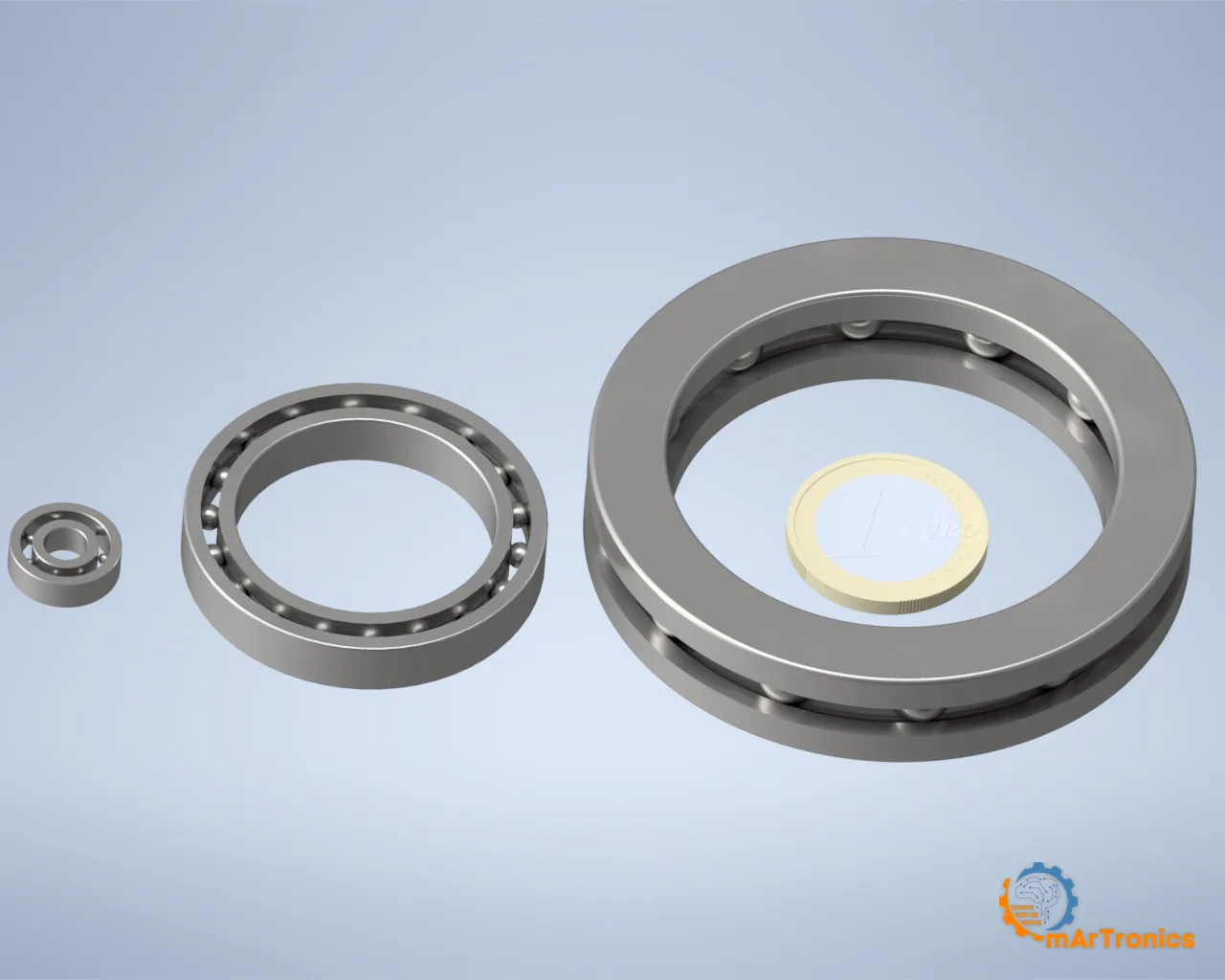
ثلاثة أنواع من المحامل لسبعة مفاصل، وتجد سبب اختيار كل منها في القسم 5. ونقطتان مكانهما هنا. ZZ تعني دروعًا معدنية على الجانبين. تمنع هذه الدروع غبار الطباعة من دخول مجاري الكرات، وهذا مهم في آلة تقف بجوار طابعة ثلاثية الأبعاد (3D). أما الحجة ضد الجُلب العادية (Bushings) فهي حسابية بحتة. عُشر مليمتر من الخلوص عبر شوكة الكتف بعرض 60 mm يعني ميلًا بمقدار 0.1 درجة، و0.1 درجة على بعد 485 mm تعني 0.8 mm عند أطراف الأصابع.
اختيار السيرفو: DS3240، وماذا تعني “40 kg”
سيرفو المفاصل هو DSSERVO DS3240-180، وأول ما يجب توضيحه هو الرقم الكبير المطبوع على جانبه.
مكتوب على الهيكل 40 kg. أما جدول المواصفات في ورقة البيانات نفسها فلا يحتوي إلا على عمودين للجهد: 36 kg·cm عند 5 V و 45 kg·cm عند 6.8 V. وإذا أجريت الاستيفاء (Interpolation) بين هاتين النقطتين تصل إلى 41 kg·cm عند 6 V، ووصف المنتج في ورقة البيانات هو حرفيًا “6V 40kg RC Digital Servo”. الرقم 40 هو قيمة 6 V مقرّبة إلى الأدنى. إنه رقم حقيقي، لكنه مذكور عند جهد لا يرد أبدًا في جدول المواصفات، وليس ما تحصل عليه عند 5 V.
| جهد خط التغذية | عزم التوقف (Stall Torque) | السرعة بلا حمل | تيار التوقف | الكتف عند 23.60 kg·cm |
|---|---|---|---|---|
| 5.0 V | 36 kg·cm | 0.20 s/60° = 300 °/s | 3.10 A | 65.6 % من عزم التوقف، فوق الحد |
| 6.0 V، القياسي | 41 kg·cm | 0.183 s/60° = 327 °/s | 3.54 A | 57.6 % من عزم التوقف |
| 6.8 V | 45 kg·cm | 0.17 s/60° = 353 °/s | 3.90 A | 52.4 % من عزم التوقف |
قيم 5 V و6.8 V مأخوذة من صفوف ورقة البيانات؛ أما سطر 6 V فهو استيفاء خطي بينهما.
أرقام نسبة الاستخدام والحمولة في القسم 4 تستخدم صف 6 V، لأن 6 V هو جهد خط التغذية القياسي. ومزود الطاقة الذي يهبط جهده يدفع محركات السيرفو نحو صف 5 V، الذي يذكره جدول الحمولة بشكل منفصل. ولا يمكن رفع جهد خط التغذية أكثر: فسيرفو القابض SG90 يشترك فيه، وأقصى جهد مقنن له 6 V. وحد 6 V هذا هو أيضًا الجهد الذي تعطي عنده محركات سيرفو المفاصل عزمها المعلن 40 kg.
أربكتني أسماء الطرازات المتشابهة أنا أيضًا. فبين عروض DS3218 وDS3240 المتطابقة تقريبًا، بقيت فترة مقتنعًا بأنني أملك الطراز الآخر. طابِق رقم الطراز مع ملف PDF لورقة البيانات قبل أن تطلب.
قيم ورقة البيانات التي حسمت الاختيار:
عزم التوقف 36 kg·cm عند 5 V، و41 عند 6 V. القسم 4 يُبيّن أن الكتف يحتاج إلى سيرفو مقنن بعزم 37.5 kg·cm على الأقل، وهو أعلى من قيمة 5 V وضمن قيمة 6 V؛ ولهذا تعمل الذراع على 6 V. والفئة الأدنى، أي نطاق 18 إلى 24 kg·cm، ستدفع الكتف إلى ما فوق 100 بالمئة عند الحمولات المفيدة. أما الفئة الأعلى فتكلف أكثر، وتزن أكثر، وتضيف عزمًا لا يستطيع الهيكل المطبوع الاستفادة منه.
النطاق الميت (Dead Band) 3 µs. على نطاق 500 إلى 2500 ميكروثانية المقابل لـ 180 درجة، تساوي 3 µs ما مقداره 0.27 درجة، وهو حد الدقة (Resolution) للذراع. أما اختبار القلم في القسم 10 فيقيس دقة التكرار (Repeatability) التي تحصل عليها فوق هذا الحد. وللمقارنة، 0.27 درجة عند القاعدة تعني نحو 2.3 mm عند طرف الإصبع عند أقصى مدى وصول.
السرعة 0.20 s/60° عند 5 V، أي 300 درجة في الثانية دون حمل. البرنامج الثابت لا يحرّك المفاصل بهذه السرعة أبدًا، وكل طبقة برمجية فوق السيرفو تحدد هامش سرعتها انطلاقًا من هذا الحد الأقصى في ورقة البيانات.
تيار التوقف 3.1 A عند 5 V (3.9 A عند 6.8 V). وميزانية الطاقة في القسم 4 تبدأ من هذا الرقم.
بقية المواصفات الميكانيكية: علبة تروس معدنية بنسبة 342:1، وعمود خرج بمحملين، وهيكل محكم بتصنيف IP66، ووزن 60 g، ومحزّز خرج 25T، ومعدل تحديث مقبول من 50 إلى 330 Hz. يعني IP66 أن الهيكل محكم ضد الغبار ومحمي من نفثات الماء. ومعدل التحديث يتحول أدناه إلى قرار في التوصيلات.
القسم 4 يشرح لماذا يُركَّب السيرفو نفسه في المفاصل الستة كلها.
سيرفو القابض، ولماذا غيّر توصيلات الإلكترونيات
يعمل القابض بسيرفو SG90: وزنه 9 غرامات، تناظري، وهو السيرفو المصغّر نفسه الذي استخدمه Zero. ترسا القابض بالحجم نفسه ويتعشّقان بنسبة 1:1، لذا يحافظ الزوج على حركة الفكّين معًا ولا يضاعف قوة السيرفو. ومع ذلك حمل SG90 الحمولة البالغة 325 g في اختبار الحمولة في القسم 10.
SG90 تناظري ولا يقبل إلا 50 Hz، بينما تعمل محركات DS3240 الستة على 250 Hz عبر PCA9685 (القسم 8 يشرح السبب). اللوحة الواحدة تعمل بتردد واحد، لذا يحصل القابض على مؤقّت 50 Hz خاص به على طرف من أطراف ESP32: ستة مفاصل على PCA9685 بتردد 250 Hz، وقابض واحد على طرفه الخاص بتردد 50 Hz.
ESP32 وPCA9685
كلاهما مأخوذ من Zero؛ وتجد في منشور Zero الشرح المفصّل. يوفّر ESP32 الواي فاي (Wi-Fi)، وقدرة معالجة كافية لتشغيل خادم ويب إلى جانب حلقة الحركة، ومنفذًا تسلسليًا عبر USB للبرنامج الثابت التسلسلي الخاص بـ ROS 2 لاحقًا. أما PCA9685 فسبب وجوده أن إشارة PWM المولّدة في عتاد مخصص لا ترتجف (Jitter) عند حدوث مقاطعات الواي فاي. تضبط عرض النبضة عبر I2C فيحافظ عليه. وتشغيل محركات السيرفو الستة بهذه الطريقة لا يتطلب من ESP32 سوى سلكي I2C الاثنين.
تقع اللوحتان داخل هيكل القاعدة، لذا لا توجد لوحة تجارب (Breadboard) متدلية من خلف هذه الذراع.
حساب قدرة مزود الطاقة
القسم 4 يتضمن الحساب: نحو 4.3 A في الحركة المعتادة، أما الحالة القصوى فلا تحدث إلا عندما تُعاق حركة جميع المفاصل. ويغطي مزود طاقة بجهد 6 V وتيار 10 A كل ما يمكن عدّه تشغيلًا فعليًا، بينما يمتص المكثف بسعة من 1000 إلى 2200 µF التغيرات العابرة في التيار.
يتحدد جهد خط التغذية بالحد الأقصى لمحرك SG90 وهو 6 V. ويبقى خط التغذية المشترك عند 6 V رغم أن محركات DS3240 تتحمل 6.8 V وتعطي عندها 45 kg·cm. ويُفقد ذلك محركات سيرفو المفاصل أعلى 4 kg·cm من عزمها. وفي المقابل تحتاج الذراع إلى خط تغذية واحد فقط، من دون مزود طاقة ثانٍ ومن دون محوّل مستوى الجهد (Level Shifter، وهو دارة تحوّل الإشارة من مستوى جهد إلى آخر).
مزود الطاقة على طاولة عملي هو HANMATEK HM305P، وهو جهاز صغير قابل للبرمجة مضبوط على 6.00 V، وحد التيار فيه 5 A، أي أقل من 10 A التي يوصي بها هذا القسم. ومع ذلك فهو يعمل، لسببين. فحدود السرعة في نواة الحركة (Motion Core) تُبقي استهلاك الذراع المعتاد عند نحو 4.3 A. وعندما تتطلب حركة ما تيارًا أكبر، ينتقل المزود إلى وضع التيار الثابت: يثبّت التيار عند حده ويترك الجهد ينخفض، فلا يحترق شيء. وهذا الانخفاض يقرّب أداء المفاصل من عمود 5 V في جدول الحمولة. وللتركيب الدائم يبقى مزود طاقة ثابت بقيمة 6 V / 10 A الخيار الأفضل؛ أما ميزة مزود الطاقة المختبري فهي شاشة العرض.
يتحمّل المفتاح الهزاز KCD1 ومقبس الطاقة DC الأسطواني 5.5 x 2.1 mm في القاعدة نحو 6 A و5 A على الترتيب. وهذا يكفي لإعداد مزود الطاقة المخبري الموضَّح أعلاه، لأنه يحدّ التيار عند 5 A. لا تشغّل خط تغذية السيرفو أو تفصله إلا والذراع ساكنة. إذا كان مزود الطاقة لديك يعطي أكثر من 6 A، فاستخدم مفتاحًا مقنّنًا لتيار مستمر (DC) لا يقل عن 15 A، ووصّل مزود الطاقة مباشرة بأطراف التوصيل اللولبية في PCA9685 بدلًا من المقبس.

7. دليل التجميع
التسلسل التالي هو نفسه الذي يعرضه تجميع CAD: تبدأ بالصندوق الذي تقف عليه الذراع، لأن الإلكترونيات يجب أن تُركَّب قبل إغلاق القاعدة.

قبل أن تبدأ
يضغط سيرفو المفصل المتوقف (Stall) بكامل عزمه البالغ 41 kg·cm عند تغذيته من خط 6 V. وعلى امتداد 485 mm كاملة حتى أطراف أصابع القابض يعادل ذلك قوة متواضعة قدرها 0.85 kg. أما على بعد ثلاثة سنتيمترات من محور المفصل، وهو تقريبًا الموضع الذي يعلق فيه الإصبع، فيبلغ التوقف نفسه نحو 14 kg من قوة الضغط. لا شيء هنا قاتل، ولا يحتاج أي منه إلى معدات وقاية، لكن الذراع قد تؤذيك عن قرب، لذا التزم بخمس عادات منذ أول برغي.
- أبعد أصابعك عن فجوات المفاصل ما دامت محركات السيرفو موصولة بالطاقة. فالشوكات تنغلق على نفسها، والسيرفو لا يشعر بوجود عائق.
- افصل خط تغذية السيرفو أثناء العمل على الذراع. يتولى ذلك المفتاح الموجود في خط + الخاص بالسيرفو، بينما يواصل ESP32 العمل عبر USB، فتبقى صفحة الويب متاحة دون أن يتمكن أي شيء من تحريك الذراع. أعد تشغيله والذراع في الوضع الذي تركها فيه البرنامج الثابت آخر مرة، أو ويداك بعيدتان عنها.
- أخلِ الطاولة قبل تفعيل محركات السيرفو لأول مرة. صُممت الذراع بحيث لا تتحرك عند الإقلاع، لذا فالحركة التي يجب أن تحسب حسابها هي أول حركة بعد تفعيل الإخراج.
- أبعد يديك قبل تأكيد أي وضعية. بعد إعادة تشغيل الطاقة أو رفع الكود، يسأل البرنامج الثابت عن موضع الذراع. ومهما كانت إجابتك، فإنه يشغّل محركات السيرفو عند تلك الزوايا. القسم 8 يشرح هذه الآلية.
- الخطر في التيار. ستة فولتات لن تؤذيك. لكن تيارًا من عشرة إلى عشرين أمبيرًا يمر في سلك سيرفو حدثت فيه دارة قصر يسبب خطر الحروق والدخان، لذا تحقق من القطبية قبل تشغيل المفتاح وأبقِ الأطراف المكشوفة متباعدة.
وقاعدة أخرى توفر عليك قطعة:
اضبط كل سيرفو على المنتصف كهربائيًا قبل تركيب ذراع السيرفو (Horn) عليه. وصّل السيرفو، وزوّد اللوحة بالطاقة، وأرسل أمر 90 درجة، وبعد ذلك فقط اضغط ذراع السيرفو في مكانه بالزاوية التي يحددها تصميم CAD. السيرفو المركّب بزاوية ذراع خاطئة يفقد جزءًا من مداه عند أحد الطرفين ويصطدم بمصدّه الميكانيكي عند الطرف الآخر. في بنائي استخدمت 0 درجة بدلًا من 90. فبعد توصيل محركات السيرفو غير المركّبة بلوحة القيادة كما يوضح المخطط الكهربائي، ضبطتها جميعًا على 0 في تطبيق الويب الموضح في القسم 9. الزاوية 0 درجة هي نهاية مدى حركة كل مفصل، أي النقطة التي يبدأ منها المفصل، لذلك رُكّبت كل ذراع سيرفو ومفصلها عند تلك النهاية. وفي كلتا الحالتين، تحقق من اتجاه دوران كل سيرفو قبل تركيب ذراعه.
لكل خطوة من الخطوات الست عشرة التالية رسم متحرك من CAD يوضح العملية. كل منها مقطع قصير متكرر يُظهر تركيب القطعة من زاوية عملك، وترتيب عرضها هو ترتيب البناء نفسه.
الخطوة 1: تركيب الإلكترونيات في هيكل القاعدة

أنجز كل التوصيلات قبل أن تغلق أي شيء. أوصّل القاعدة أولًا لأنه بعد تركيب المنصة الدوارة لا يمكن الوصول إلى حجرة الإلكترونيات إلا بتفكيك الذراع. القسم 8 يشرح التوصيلات بالتفصيل؛ أنجزها أولًا ثم عد إلى هنا.
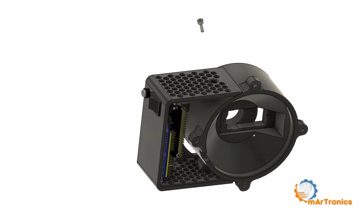
الخطوة 2: سيرفو القاعدة

ثبّته بالبراغي، لكن لا تركّب ذراع السيرفو بعد. فذراع السيرفو تُركّب في الخطوة 4، بعد ضبط السيرفو على المنتصف كهربائيًا، وهي القاعدة المذكورة في بداية هذا القسم.

الخطوة 3: محملا القاعدة

افحص المقعدين كليهما بالقدمة (Caliper) قبل أن تكبس أي شيء. كثيرًا ما تخرج الثقوب المطبوعة بتقنية FDM أصغر من مقاسها. فالمقعد المصمم بقطر 42 mm إذا خرج بقطر 41.7 لن يستوعب المحمل 6806ZZ. وإدخاله بالقوة يشق القطعة المطبوعة على امتداد إحدى الطبقات، وغالبًا ما يحدث ذلك وأنت تضغط عليها بالملزمة، في لحظة لا يمكنك فيها التوقف.

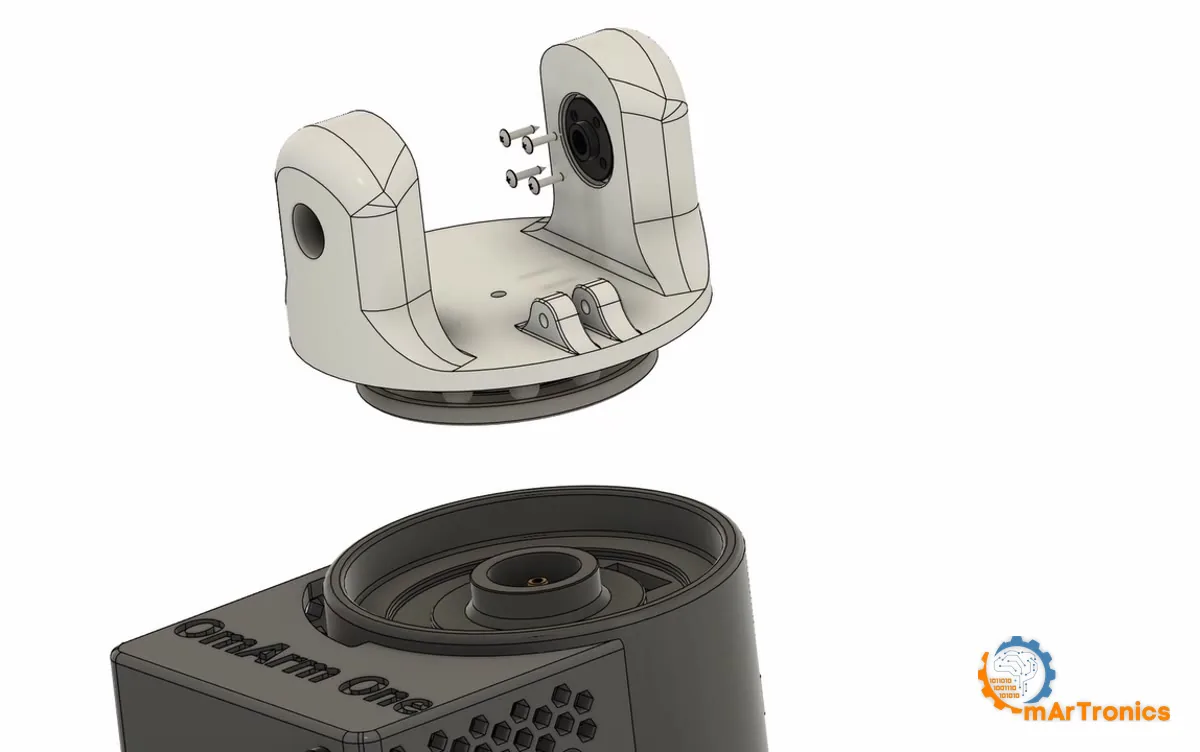
الخطوة 4: تركيب المنصة على القاعدة

من هذه الخطوة فصاعدًا، تدور المنصة على محامل فولاذية. أمسك القاعدة المجمّعة وحاول هزّها: ستقاومك حلقة المحامل. أما في OmArm Zero فكان محزّز السيرفو هو الذي يتحمل هذا الحمل.

الخطوة 5: الذراع العلوية على طاولة العمل

تحمل هذه الوصلة وحدها محركي سيرفو، واحدًا عند كل طرف: يحرّك J2 الكتف أسفلها، ويحرّك J3 المرفق أعلاها. وكلتا ذراعي السيرفو متجهتان إلى الخارج، لذا يُغلق المفصلان لاحقًا على قطع مركّبة مسبقًا على الآلة.
هذه هي الخطوة التي وضعتها في المكان الخطأ لفترة طويلة، والرسم المتحرك هو ما صحّح ذلك. جمّع الذراع العلوية كاملة أولًا. فبمجرد أن تتدلى في شوكة الكتف، ستعمل بيد واحدة، فوق قاعدة توشك على الانقلاب، وبمفك لا يمكنك جعله عموديًا على البرغي.

الخطوة 6: الكتف والنابض

تحمل المنصة شوكة بساقين، في كل ساق ثقب أملس، ولا يوجد تجويف للسيرفو في أي منهما: فسيرفو J2 رُكّب في الذراع العلوية في الخطوة 5. اكبس المحمل 695ZZ في إحدى ساقي الشوكة، وأنزل الذراع العلوية المكتملة بين الساقين، وثبّت ذراع السيرفو بالبراغي في ساق الشوكة المقابلة. ثم مرّر الجلبة عبر المحمل وأدخل المسمار الملولب M5 x 25 مع صامولته من الخارج؛ فالكتف يأخذ أطول المسامير الملولبة الثلاثة.
اربط حتى تتأرجح الذراع بحرية تحت وزنها دون أي خلوص جانبي. هذا المزيج، حركة حرة بلا ارتخاء، هو الإحساس المفترض في ترتيب التثبيت الثابت والحر (Fixed-Loose). وإذا ازداد المفصل تيبسًا كلما شددت، فالجلبة أقصر من اللازم وساقا الشوكة تنسحبان إلى الداخل.


يختتم النابض هذه الخطوة. علّقه بين نتوءي التثبيت المطبوعين، أحدهما على المنصة والآخر على الذراع العلوية، وثبّت كلا طرفيه بمسمار تثبيت (Pin). فهو يسحب الذراع إلى الأعلى.
الخطوة 7: نمط مفصل اللف (Roll)

هذا هو النمط الثاني من النمطين، ومن هنا فصاعدًا تتكون الذراع من تكرار هذين النمطين. فمفصل اللف ليس له شوكة ولا جانب حر. يستقر السيرفو في المقطع، وتُركّب ذراع السيرفو على محزّزه، ويُثبّت المقطع التالي بالبراغي مباشرة على ذراع السيرفو.


الخطوة 8: إغلاق المرفق

القاعدة نفسها كما في الكتف: اربط حتى يتحرك المفصل بحرية دون خلوص جانبي، وتوقف عندما يبدأ بالتيبس.
الخطوة 9: مفصل لف الساعد، المحمل وذراع السيرفو

هذا هو المفصل J4، وهو المفصل الوحيد خارج القاعدة الذي يحصل على محمل 6806ZZ؛ القسم 5 يوضح السبب.
الخطوة 10: تركيب مقطع لف الساعد على الذراع

مرّر المقطع فوق ذراع السيرفو، وأدخل البراغي الأربعة، وتحقق من أن مفصل اللف يدور بحرية قبل أن تنتقل إلى ما بعده. يدخل المسمار الملولب M5 من الجانب في نهاية هذه الخطوة؛ أما صامولته فتنتظر الخطوة التالية. وهذه أيضًا آخر فرصة سهلة لتمرير كابلات المعصم عبر المقطع، فافعل ذلك الآن، قبل الخطوة 12.
الخطوة 11: سيرفو المعصم

هذه الصامولة هي الثالثة والأخيرة من مجموعات M5 الثلاث، وهي تُحكم المسمار الملولب الذي أدخلته في نهاية الخطوة 10. اضبط السيرفو على المنتصف قبل تركيب ذراع السيرفو. فكل مفصل من هنا فصاعدًا قريب من حدوده الميكانيكية إلى درجة أن انحراف ذراع السيرفو بسنّ واحدة من المحزّز يُفقدك جزءًا ملحوظًا من مدى الحركة.
الخطوة 12: مفصل ميل المعصم (Pitch)

هذا آخر محركات DS3240 الستة، وهنا تحمل الشوكة جسم السيرفو نفسه. تثبّته أربعة براغٍ، كما في كل المواضع الأخرى. اضبطه على المنتصف قبل تركيب ذراع السيرفو، وتحقق من أن المفصل يتأرجح بحرية قبل أن تُغلق الخطوة التالية الوصول إلى هذه البراغي.
الخطوة 13: إغلاق المعصم

بمجرد إدخال هذا البرغي يصبح المعصم وحدة مغلقة. حرّك مفاصل المعصم الثلاثة كلها يدويًا عبر مداها مرة واحدة؛ فأي احتكاك الآن سيتطلب إصلاحه لاحقًا خطوتين من التفكيك.
الخطوة 14: شفة الأداة

المفصل J6 هو الاستثناء هنا. فهو يعمل على ذراع السيرفو وحدها، دون محمل؛ القسم 5 يعرض الأرقام.
الخطوة 15: قاعدة القابض

أربعة براغٍ M3 ذات رأس سداسي مجوف تمر عبر القاعدة إلى الشفة. يكفي ربطها بإحكام خفيف؛ فالأسنان المطبوعة تتلف قبل البراغي.
الخطوة 16: القابض

أغلق الفكين يدويًا قبل تركيب ذراع السيرفو، لتعرف اتجاه حركة زوج التروس، ثم اضبط السيرفو على المنتصف وركّب ذراع السيرفو عند وضع الفتح الكامل.
بعد الخطوات الست عشرة: تمديد الكابلات
يجب أن تصل سبعة كابلات سيرفو إلى القاعدة دون أن تنضغط عند أي مفصل أو تنشد عند الامتداد الكامل. مدّدها على طول الجانب الداخلي للوصلات، واترك عند كل مفصل حلقة خدمة (Service Loop، وهي حلقة من الكابل الزائد تسمح للمفصل بالحركة دون أن يشد الكابل). وافحص المدى الكامل لكل مفصل يدويًا قبل أن تقترب الطاقة من الذراع أصلًا.
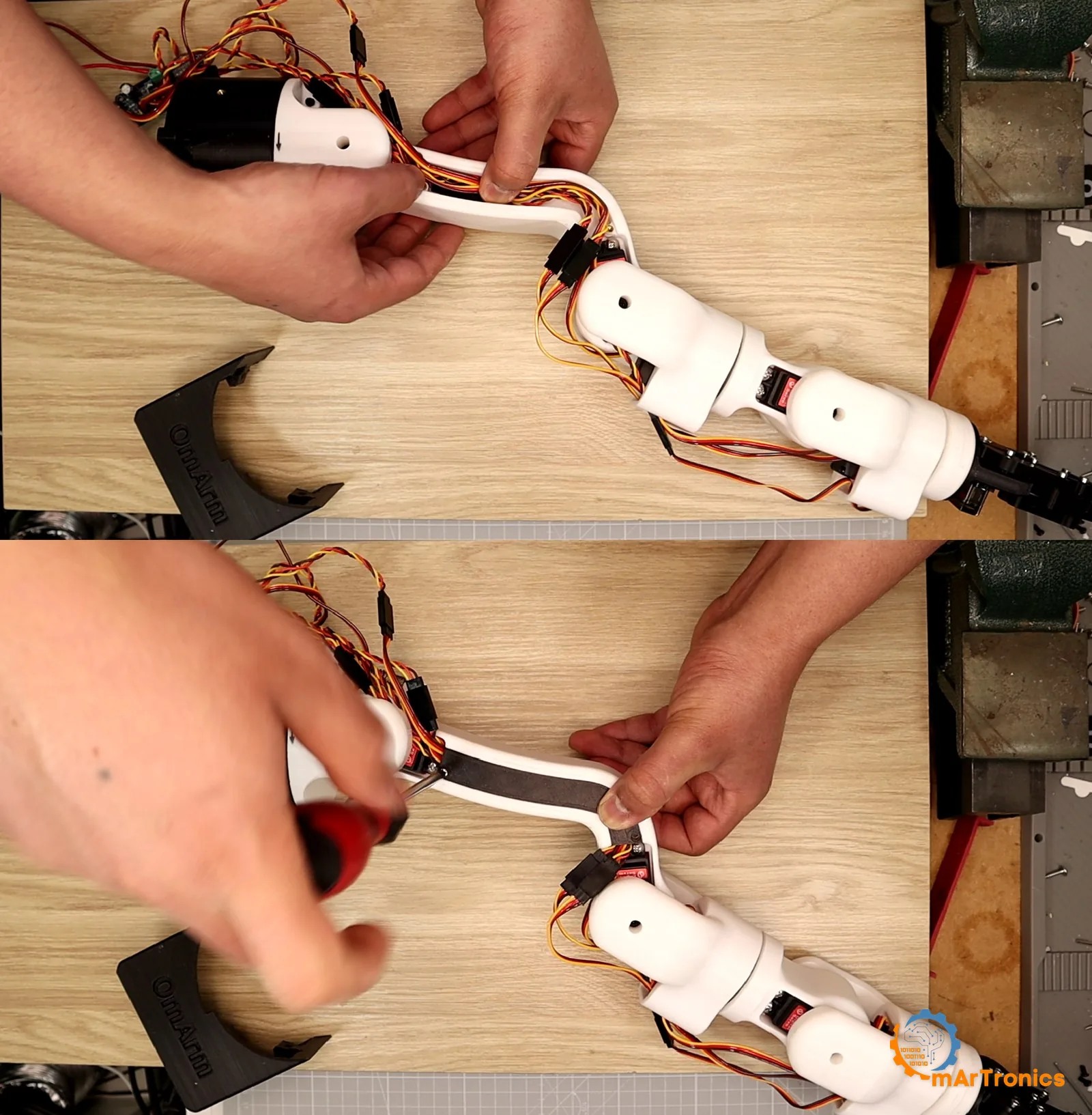
كل عناصر التثبيت المستخدمة في هذه الخطوات الست عشرة مفصّلة بندًا بندًا في القسم 6، بما في ذلك جدول يبيّن موضع كل برغي مرتبط بأرقام الإشارات (Balloon Numbers) في الرسم. وينقص هناك جزآن لأن نموذج التجميع لا يتضمنهما: الحشوات الملولبة الحرارية M3 في وصلات القابض، والبرغيان الصغيران المرفقان في كيس SG90 نفسه.
8. التوصيلات والتشغيل الأول
هناك دارتان، ومعظم عمل التوصيلات يدور حول إبقائهما منفصلتين. مسار إشارة يمتد من ESP32 إلى محركات السيرفو، ومسار طاقة يمتد من مزود الطاقة إلى محركات السيرفو دون أن يمر بـ ESP32.
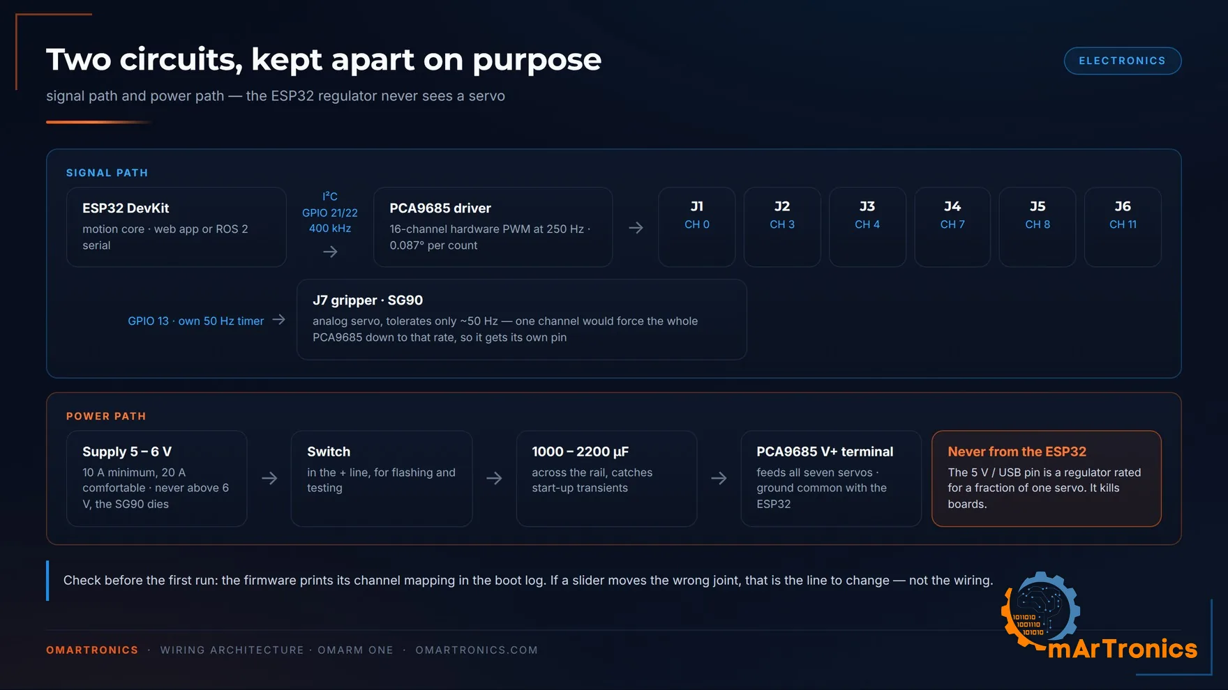
التوصيلات

| من | إلى | ملاحظة |
|---|---|---|
| ESP32 GPIO 21 (SDA) | PCA9685 SDA | I2C بتردد 400 kHz |
| ESP32 GPIO 22 (SCL) | PCA9685 SCL | |
| ESP32 3V3 | PCA9685 VCC | تغذية المنطق لشريحة القيادة فقط |
| ESP32 GND | PCA9685 GND | أرضي مشترك، إلزامي |
| ESP32 GPIO 13 | إشارة SG90 | مؤقت خاص بتردد 50 Hz، وليس على PCA9685 |
| مزود الطاقة + (6 V) | الطرف اللولبي V+ في PCA9685 | مع مكثف من 1000 إلى 2200 µF على طرفيه |
| مزود الطاقة − | طرف GND اللولبي في PCA9685 | |
| SG90 + / − | خط تغذية السيرفو | طرفا V+/GND في صف أطراف التوصيل للقناة 12 على PCA9685 |
| المفتاح | في خط + الخاص بالسيرفو | استخدمه أثناء التحميل على اللوحة والاختبار |
| USB | ESP32 | مصدر التغذية الوحيد لـ ESP32 |
تعمل الذراع بمصدري تغذية، ومن السهل الخلط بينهما. يغذي مزود 6 V محركات السيرفو ولا شيء غيرها. أما ESP32 فيتغذى عبر USB، ويغذي بدوره طرف المنطق في PCA9685 من خط 3V3 الخاص به. افصل USB وسيتوقف كل شيء حتى مع توصيل 6 V. وإذا أطفأت 6 V، فسيظل ESP32 يقلع ويعرض صفحة الويب، لكن لا شيء يتحرك. وهذه الحالة الثانية مفيدة، وفيها يجري التشغيل الأول الموضح أدناه.
طرف VIN أو 5V في ESP32 ليس مصدر طاقة لمحركات السيرفو. ففي لوحة DevKit المغذاة عبر USB يتغذى هذا الطرف من مصدر USB، الذي لا يوفر إلا جزءًا صغيرًا من تيار التوقف لسيرفو واحد.
توزيع القنوات
يتوقع البرنامج الثابت أن تكون المفاصل من J1 إلى J6 على قنوات PCA9685 0 و3 و4 و7 و8 و11. وزّعت محركات السيرفو على صف الأطراف لأترك مساحة للموصلات وأُبقي التوصيلات سهلة القراءة.
| المفصل | J1 | J2 | J3 | J4 | J5 | J6 | J7 |
|---|---|---|---|---|---|---|---|
| القناة | 0 | 3 | 4 | 7 | 8 | 11 | ESP32 GPIO 13 |
تظهر الأرقام الستة نفسها في برنامج Arduino (Sketch) على شكل SERVO_CHANNELS[] = {0, 3, 4, 7, 8, 11}، وهي تطابق الرسم أعلاه وصلةً بوصلة. ويطبع البرنامج الثابت هذا التوزيع أيضًا في سجل الإقلاع، فتستطيع أن تقرأ ما يعتقد أنه موصول. وإذا حرّك منزلق ما المفصل الخطأ، فغيّر ذلك السطر واترك التوصيلات كما هي. وهذا ما يقوله البرنامج نفسه في التعليق الموجود في رأس الملف.
تم التحقق من ذلك على الذراع المجمّعة: حزمة الأسلاك تطابق المخطط الكهربائي، وخريطة القنوات في سجل الإقلاع تطابق ما تحركه المنزلقات.
قرار 250 Hz، والفخ الكامن فيه
تقود شريحة PCA9685 محركات السيرفو الستة الخاصة بالمفاصل بتردد 250 Hz، وهو داخل نطاق DS3240 المسموح من 50 إلى 330 Hz بهامش واسع. ومضاعفة التردد التقليدي خمس مرات تُصغّر وحدة العدّ الواحدة في سجل PWM من 0.44 درجة عند المفصل إلى 0.086 درجة. وبما أن المنطقة الميتة (Dead Band) للسيرفو نفسه تبلغ 0.27 درجة، فإن هذه المنطقة الميتة هي التي تحدد حد الدقة عند 250 Hz.
والآن الفخ. لا تعمل شريحة PCA9685 بالتردد الذي تطلبه، بل تقسم تردد مذبذبها الداخلي على عدد صحيح هو المقسِّم المسبق (Prescaler):
f = osc / (4096 × (prescale + 1))
عند 50 Hz يبلغ خطأ التقريب 0.06 بالمئة ولا يلاحظه أحد. أما عند 250 Hz فأقرب قيمة للمقسِّم المسبق هي 23، وهي تعطي 254.3 Hz، أي بانحراف قدره 1.7 بالمئة. لذلك تعمل الشريحة بدورة زمنية (Period) أقصر مما طلبت، فتأتي قيم العدّ للنبضات المحسوبة على أساس التردد الاسمي 250 Hz أقل بنسبة 1.7 بالمئة. والنتيجة خطأ في الكسب (Gain Error) يكبر على امتداد مدى الحركة: 0.8 درجة عند أحد طرفي المدى، و2.3 في المنتصف، و3.8 عند الطرف الآخر، وذلك في كل محور. وقيمة 0.086 درجة لكل وحدة عدّ المذكورة أعلاه مأخوذة من 254.3 Hz نفسها: فتردد 250 Hz بالضبط كان سيعطي 0.088، والـ 4.3 Hz الزائدة هي سبب الفرق في آخر جزأين من الألف من الدرجة. لذلك أحسب كل قيمة عدّ من المقسِّم المسبق الموجود فعلًا في الشريحة، ولا أحسبها أبدًا من التردد الذي طلبته. وإذا كتبت كود التحكم الخاص بك، فاتّبع هذه العادة.
التشغيل الأول
ثبّت المكتبتين اللتين يحتاجهما برنامج Arduino (Adafruit PWM Servo Driver Library و ArduinoJson)، وحمّله على اللوحة، واترك مفتاح طاقة السيرفو مطفأً في الإقلاع الأول. راقب السجل التسلسلي: فهو يطبع توزيع القنوات، والتردد الفعلي لشريحة PCA9685، وما إذا كان مؤقّت القابض قد رُبط بنجاح.
ثم اتصل بنقطة وصول واي فاي (Wi-Fi) OmArmOne (كلمة المرور omarmcontrol) وافتح http://10.10.10.1. تطبيق الويب مضمَّن داخل برنامج Arduino، ويكتب نفسه في نظام ملفات ESP32 عند الإقلاع الأول، فلا يلزم رفع أي شيء آخر.
ما يهم في آلة بهذا الثقل هو ما يحدث بعد إعادة الضبط (Reset). لا تملك الذراع تغذية راجعة للموضع، لذا يستيقظ البرنامج الثابت دون أن يعرف أين هي. السلوك الساذج، وهو ما كانت تفعله نسختي السابقة من هذا الكود، هو تحريك كل مفصل إلى الصفر بأقصى سرعة عند الإقلاع. وفي ذراع بهذا الثقل يجعل ذلك كل عملية رفع للبرنامج على اللوحة خطرَ سحق. بدلًا من ذلك:
- تُحفظ الوضعية في سجلّين. نسخة في ذاكرة RTC (كتلة ذاكرة صغيرة تحتفظ بمحتواها عند إعادة ضبط المعالج) تُحدَّث مع كل دورة تحديث للسيرفو (Servo Tick)، فتبقى إعادة الضبط في منتصف الحركة آمنة. ونسخة في ذاكرة الفلاش (Flash) تُكتب بعد لحظة من توقف الذراع. ذاكرة RTC تصمد أمام إعادة ضبط المعالج لكنها لا تصمد أمام انقطاع الطاقة وعودتها، وهذا هو الحد نفسه الذي يرسمه منطق تحديد سبب إعادة الضبط.
- بعد إعادة ضبط برمجية أو انهيار البرنامج، يستعيد البرنامج الثابت تلك الوضعية ويعيد إرسال الأوامر إلى محركات السيرفو بالمواضع نفسها التي تقف فيها بالضبط، فلا يتحرك شيء.
- بعد تشغيل الطاقة، أو انخفاض الجهد (Brownout: هبوط في التغذية عميق بما يكفي لإعادة ضبط الشريحة)، أو رفع البرنامج، لا يحرّك البرنامج الثابت أي شيء على الإطلاق. يعرض تطبيق الويب تحذيرًا وينتظر منك أن تصرّح بالوضعية. وتدخل عملية الرفع ضمن هذه الحالة لأنها تعيد ضبط اللوحة عبر الطرف EN (مدخل إعادة الضبط في ESP32)، فتُبلّغ الشريحة عن ذلك على أنه تشغيل للطاقة. اطوِ الذراع أو أسندها قبل التحميل على اللوحة.
- التصريح بالوضعية قفزة وليس حركة. فزرّا التأكيد كلاهما، وكذلك الأمر SETPOS عبر USB مع البرنامج الثابت التسلسلي الخاص بـ ROS 2، تُشغّل محركات السيرفو عند الزوايا التي تصرّح بها، دفعة واحدة. وإذا لم تكن الذراع في تلك الوضعية، فإنها تقفز إليها بأقصى سرعة. قاعدة الثواني الأربع المذكورة أدناه تنطبق على أول حركة تأمر بها، لا على هذا. أبعد يديك.
- تُجبَر الحركة الأولى بعد أي إقلاع على أن تستغرق أربع ثوانٍ على الأقل، أيًّا كان موضع منزلق السرعة.
- يجمّد إيقاف الطوارئ الذراع مع بقاء محركات السيرفو ممسكة بوضعها، ويبقى مُثبَّتًا (Latched)؛ القسم 9 يشرح خطوات تحريره.

خاصيتان غير بديهيتين في جانب السيرفو عند إعادة الضبط:
- القابض موصول بالطرف GPIO 13، لذا يتوقف عن تلقي النبضات أثناء إعادة الضبط ويرتخي (دون عزم تثبيت). أفرغ فكّي القابض قبل التحميل على اللوحة.
- تحتفظ المفاصل J1 إلى J6 بنبضتها القادمة من PCA9685 خلال إعادة الضبط نفسها، لكن برنامج Arduino يضع بعد ذلك كل قناة في حالة إيقاف كامل (Full Off) قبل أن يتعامل مع لوحة القيادة. فسجلات الشريحة تصمد أمام إعادة الضبط وهي تحمل قيم عدّ محسوبة لمعدل الإطارات السابق، وإعادة تشغيلها ستجعل المفصل يقفز نحو حدّه الميكانيكي. غياب النبضة هو الحالة الوسيطة الآمنة. ولا تعود القنوات الست إلا بعد أن يقبل البرنامج الثابت وضعية، لذا تبقى مرتخية في حالة طلب التأكيد أولًا حتى تجيب. خط التغذية (Rail) ما زال موصولًا بالجهد؛ النبضة وحدها هي الغائبة.
لا شيء من هذا يغني عن المفتاح الموجود في خط تغذية السيرفو. استخدمه.
9. واجهة الويب
اتصل بشبكة OmArmOne، ثم افتح http://10.10.10.1. اكتب البادئة http:// وإلا فسيتعامل الهاتف مع العنوان على أنه عبارة بحث. لا حاجة إلى تطبيق أو حساب أو اتصال بالإنترنت، لذا تعمل الذراع أيضًا في ورشة لا تصلها تغطية شبكة الهاتف المحمول، أو في فصل دراسي يُمنع فيه تثبيت البرامج.
تحذير واحد أولًا، لأنه سيكلفك عشر دقائق إن لم تنتبه له. تتعامل الهواتف مع الشبكة التي لا يوجد خلفها اتصال بالإنترنت على أنها مشبوهة. يسألك Android هل تريد البقاء متصلًا، وقد يبدأ بتوجيه حركة البيانات عبر بيانات الهاتف المحمول بدلًا منها، ويُعلّم iOS الشبكة على أنها بلا اتصال. إذا توقفت الصفحة عن الاستجابة دون سبب ظاهر، فهذا هو السبب في الغالب. أوقف بيانات الهاتف المحمول أثناء تحريك الذراع، أو أجب عن السؤال عند ظهوره.
ما الذي تراه أمامك
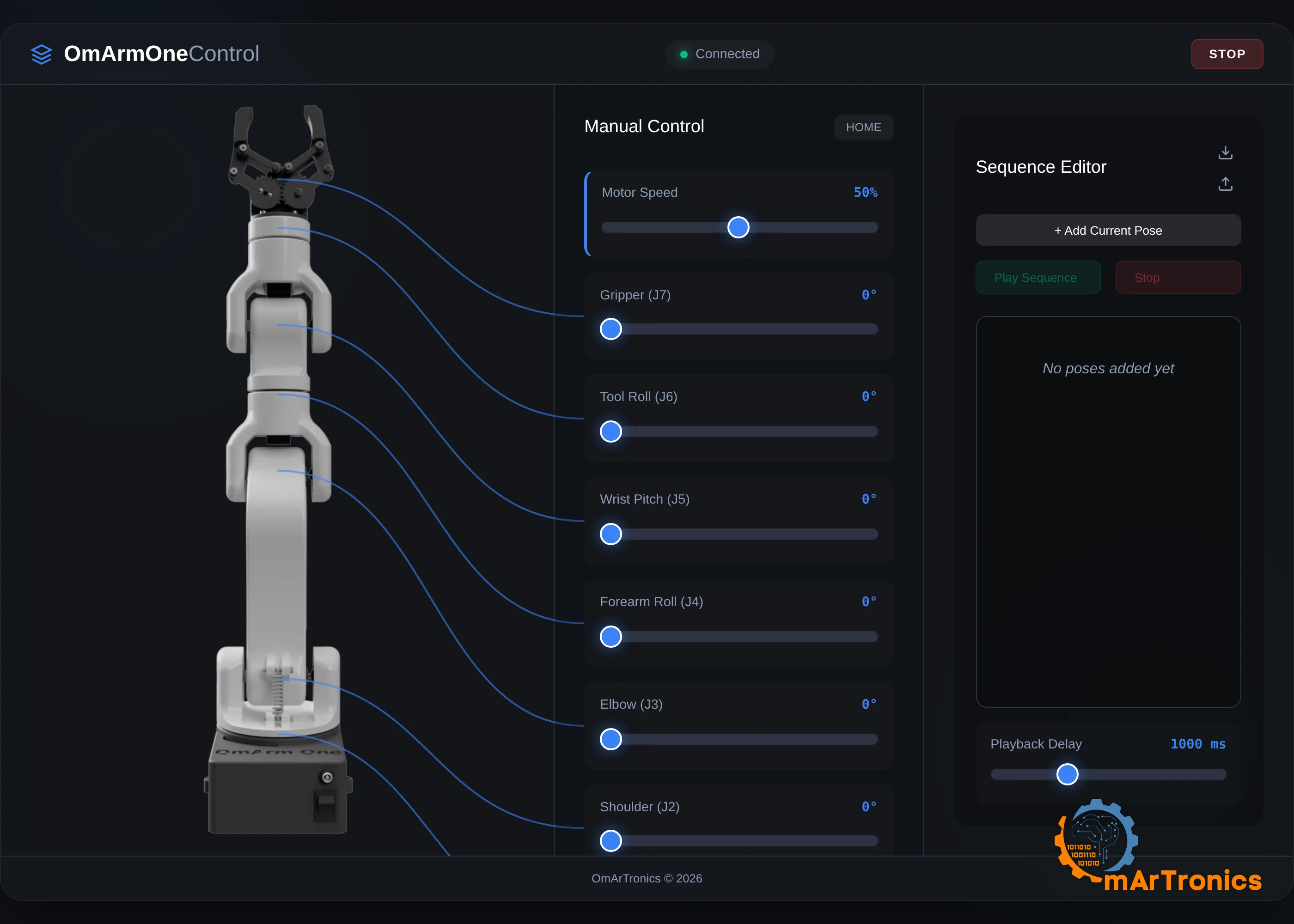
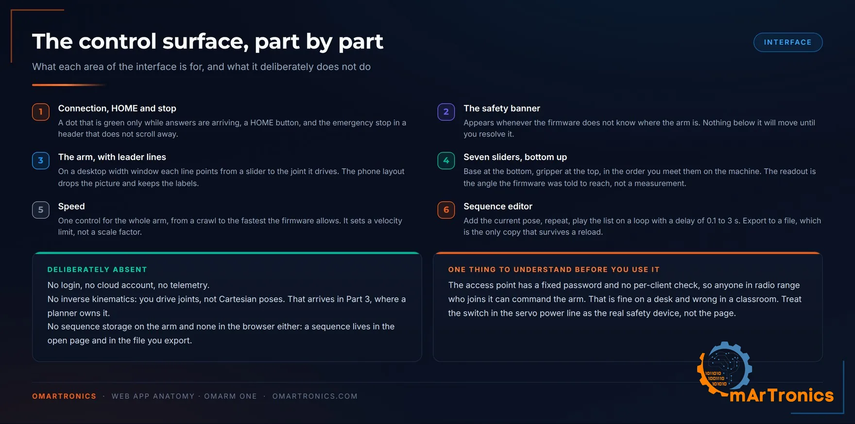
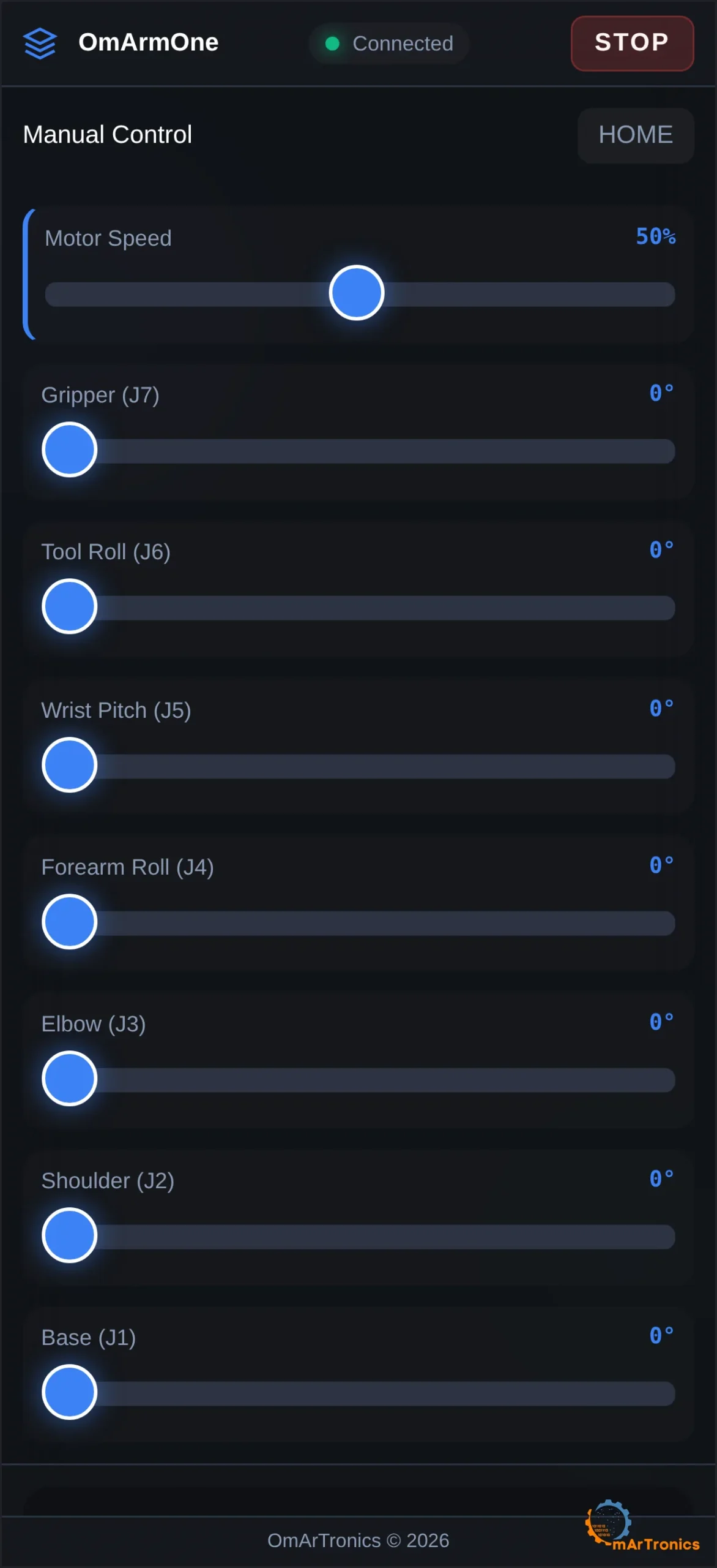
تمتد سبعة منزلقات من الأسفل إلى الأعلى بترتيب المفاصل كما تصادفها على الآلة: J1 القاعدة، وJ2 الكتف، وJ3 المرفق، وJ4 دوران الساعد (Roll)، وJ5 ميل الرسغ (Pitch)، وJ6 دوران الأداة، وJ7 القابض في الأعلى.
الرقم في كل تسمية هو الزاوية التي طُلب من البرنامج الثابت الوصول إليها. لا شيء في هذه الذراع يقيس الزاوية، لذا لا شيء في هذه الصفحة يستطيع أن يعرضها لك. أما هل وصل السيرفو إليها فعلًا فذلك سؤال منفصل، وراجع القسم 10، ففيه اختبار قابلية التكرار الذي تجيب به عن هذا السؤال على آلتك.
في نافذة أعرض من 1024 بكسل، يرتبط كل منزلق بصورة الذراع بخط إشارة. وأي عرض أضيق، كالهاتف أو نافذة على الحاسوب مثبتة على نصف الشاشة، تختفي فيه الصورة وتبقى التسميات.
فوق المنزلقات ثلاثة عناصر تحكم. تصبح نقطة الاتصال خضراء فقط عند وصول رد، لكنها ليست نبضة حياة (Heartbeat): فالطلب المعلّق يُبقيها خضراء حتى يستسلم المتصفح. أما “HOME” فينفذ حركة منسقة إلى J1 0، وJ2 45، وJ3 45، وJ4 0، وJ5 0، وJ6 0، وJ7 61، وهي الوضعية التي ينبغي أن تُركن فيها الذراع. ويقع إيقاف الطوارئ “STOP” في ترويسة الصفحة، والترويسة هي الجزء الوحيد من التخطيط الذي لا يتحرك مع التمرير أبدًا، فيبقى الزر في متناول يدك أينما مررت.
منزلق سرعة واحد يتحكم في الذراع كلها. يمتد من 1 إلى 100 بالمئة، وتحوّل الصفحة ذلك إلى حد أقصى للسرعة من 15 إلى 180 درجة في الثانية، وحد أقصى للتسارع يساوي أربعة أضعافه. يُرسَل هذان الرقمان إلى البرنامج الثابت الذي يفرضهما داخل حلقة التحكم الخاصة به، فيبقى الإعداد البطيء بطيئًا حتى لو تجمدت الصفحة في منتصف السحب.
تضبط المنزلقات زوايا المفاصل فقط. لقد استبعدت الحركيات العكسية من هذه الواجهة. أما التحكم الديكارتي (توجيه الذراع إلى موضع في الفراغ) فيأتي في الجزء 3، حيث يتولاه مخطِّط حركة (Planner) يستطيع فحص المسار بحثًا عن تصادمات قبل أن يتحرك أي شيء. فنسخة نصف عاملة في المتصفح كانت ستكون أسوأ من عدم وجودها.
ماذا يحدث أثناء سحب المنزلق
تجاوز هذا القسم إن كنت تريد تحريك الذراع فقط. فهو مهم إن أردت تعديل الواجهة أو كتابة عميل (Client) خاص بك.

يغطي كل منزلق المدى من 0 إلى 180 درجة بخطوات صحيحة، لذا يُطلق حدثًا عند كل درجة يعبرها إصبعك. وإرسالها كلها سيُثقل كاهل متحكم دقيق يغذّي في الوقت نفسه لوحة قيادة السيرفو 250 مرة في الثانية. لذلك ترسل الصفحة القيمة الأولى فورًا، ثم قيمة واحدة على الأكثر كل 50 ملّي ثانية، والقيم التي تأتي بينها يحل بعضها محل بعض. وعند إفلات المنزلق ترسل القيمة النهائية مرة أخرى، لأن رفع الإصبع داخل إحدى نوافذ الـ 50 ملّي ثانية هذه كان سيترك الذراع قبل هدفها ببضع درجات. وتتحدث التسمية عند كل درجة في كل الأحوال، فيتبع الرقم إصبعك حتى عندما تتأخر الطلبات عنه.
وفي الاتجاه المعاكس تطلب الصفحة STATUS كل ثانيتين، وتستقبل حالة الآلة كاملة في كائن JSON واحد. يتضمن الكائن الزوايا السبع، والوضعية التي كانت في ذاكرة الفلاش عند الإقلاع، وما إذا كانت حركة مخطَّطة قيد التنفيذ. كما يبيّن ما إذا كان الموضع معروفًا ومؤكَّدًا، وما إذا كان إيقاف الطوارئ مُثبَّتًا، وعدد أخطاء I2C، وعدد دورات تحديث السيرفو التي وصلت متأخرة. لا تعرض الصفحة إلا بعضها، والباقي موجود من أجل الطرفية (Terminal) أو السكربت، ولتصحيح أخطاء مفصل يتحرك بتقطّع.
كل أمر هو سطر نصي واحد. ينتقل إلى /api/command داخل جسم JSON ذي حقل واحد، {“cmd”:”HOME”}، ويعود الرد بصيغة JSON. الأمر MOVE:0,45,45,0,0,0,61 حركة منسقة تتشارك فيها المفاصل السبعة مدة واحدة وتصل معًا. والأمر 4,120 يرسل المفصل 4 وحده إلى 120 درجة. ويستخدم البرنامج الثابت التسلسلي الخاص بـ ROS 2 قواعد السطر الواحد نفسها عبر USB بدءًا من الجزء 3، فتصل الأوامر إلى كود الحركة نفسه.
شريط تأكيد الموضع
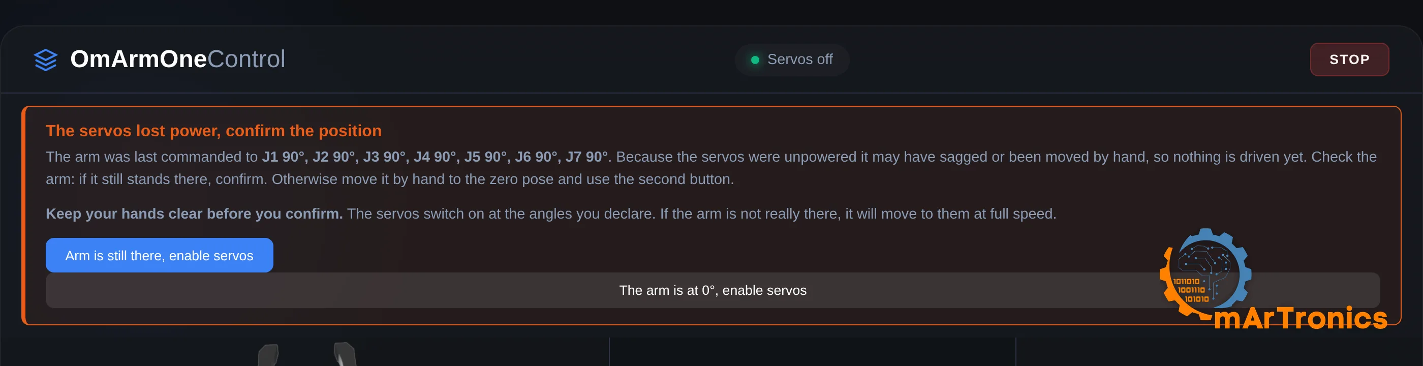
ترفض هذه الذراع الحركة في حالتين. شريط أحمر في أعلى الصفحة يعني أن البرنامج الثابت لا يعرف أين الذراع ويريد منك أن تخبره. أما غياب الشريط مع عدم حدوث أي شيء فيعني أن إيقاف الطوارئ مُثبَّت، والحل هو زر “Release the stop”. وفي الحالتين تظل المنزلقات تنزلق وتظل الأرقام تتغير، لأن الواجهة لا تعطّلها. فالرفض يحدث في البرنامج الثابت، ويظهر السبب في سطر الحالة لبضع ثوانٍ.
القسم 8 يشرح سبب رفض البرنامج الثابت (أسباب إعادة الضبط، وذاكرة RTC، والوضعية المحفوظة في الفلاش). أما هذا القسم فيعرض ما تراه في المتصفح. يعرض الشريط الوضعية التي كانت في ذاكرة الفلاش عند بدء تشغيل البرنامج الثابت. فتقارن قائمة الزوايا هذه بالذراع التي أمامك، وتقرر أي الزرين أسفله يقول الحقيقة.
يصرّح الزر “Arm is still there, enable servos” بأن الذراع تقف حيث تركها البرنامج الثابت. ويصرّح الزر “The arm is at 0°, enable servos” بأنك أدرت كل مفصل باليد حتى نهايته عند 0 درجة، بما في ذلك القابض. هذه الوضعية الثانية هي التي يمكنك بلوغها بدقة باليد، لأن كل مفصل يصطدم هناك بمصدّ ميكانيكي (Hard Stop). وهي ليست وضعية “HOME” التي تركن الكتف والمرفق عند 45 درجة.
يشغّل كلا الزرين محركات السيرفو عند الزوايا التي يذكرها، لذا فإن التصريح الخاطئ يجعل الذراع تقفز إليها بأقصى سرعة. ولهذا يتهيأ كل زر عند النقرة الأولى ولا يُنفَّذ إلا عند الثانية، ولهذا أيضًا يطلب التحذير فوقهما إبعاد يديك. وللسبب نفسه يحمل كل زر نص التصريح الذي تُدلي به.
أما إيقاف الطوارئ فيعمل بالعكس. الضغط على “STOP” يجمّد الذراع مع بقاء محركات السيرفو مُغذّاة بالطاقة وممسكة بوضعها، لأن قطع القيادة عن ذراع بهذا الثقل سيُسقطها. ثم يبقى الإيقاف مُثبَّتًا، ويرفض البرنامج الثابت كل أوامر الحركة، بما فيها الأوامر التي كانت في طريقها إليه، حتى تضغط “Release the stop”. فقد تكون هناك قيمة تنتظر خلف مُحدِّد المعدل ذي الـ 50 ملّي ثانية لحظة ضغطك الزر، كما أن هاتفًا ثانيًا على الشبكة نفسها لا يعلم شيئًا عن إيقافك.
إذا كانت الذراع تقوم بشيء خطير والصفحة لا تستجيب، فالمفتاح الموجود في خط تغذية السيرفو هو الملاذ الأخير. لكنه يُلغي عزم التثبيت أيضًا، فتسقط الذراع. أبعد كل ما تحتها قبل أن تمد يدك إليه، واستخدم زر الإيقاف على الشاشة أولًا.
محرر التسلسلات
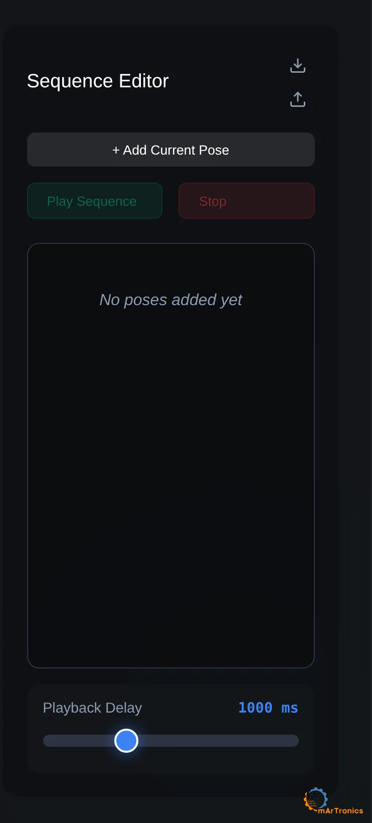
ضع الذراع في وضعية، واضغط “+ Add Current Pose”، وكرر ذلك. اضغط “Play Sequence” فتمر الذراع على القائمة بفاصل زمني تختاره بين 0.1 و3 ثوانٍ، حتى تصل إلى نهايتها، ثم تبدأ من جديد من أولها إلى أن تضغط “Stop”. وزر “Stop” هذا هو إيقاف الطوارئ نفسه الموجود في الترويسة، بما في ذلك التثبيت والتحرير.
هذا شكل مبسط من التعليم بالعرض (Teaching by Demonstration): تسجل الوضعيات يدويًا، وتعيد الذراع تنفيذها.
تبقى القائمة في الصفحة المفتوحة فقط، ولا تُحفظ في أي مكان آخر. أعد تحميل علامة التبويب وستختفي. يكتبها “Export” في الملف omarm_one_sequence.json، وهو النسخة الوحيدة التي تبقى، ويقرؤها “Import” من جديد. ويمكن أيضًا استيراد تسلسل من ست قيم من OmArm Zero: تُنقل J1 إلى J5 كما هي، ويصبح قابض Zero هو J7، ويبدأ دوران الأداة الجديد من 0. لا يُخزَّن شيء من ذلك على ESP32، فالبرنامج الثابت ليس فيه أمر للتسلسلات، ولا يعرف إلا كيف ينتقل إلى وضعية.
كيف تصل الصفحة إلى هاتفك
تجاوز هذا القسم إن كنت تريد تحريك الذراع فقط. فهو مهم إن أردت تعديل الواجهة.
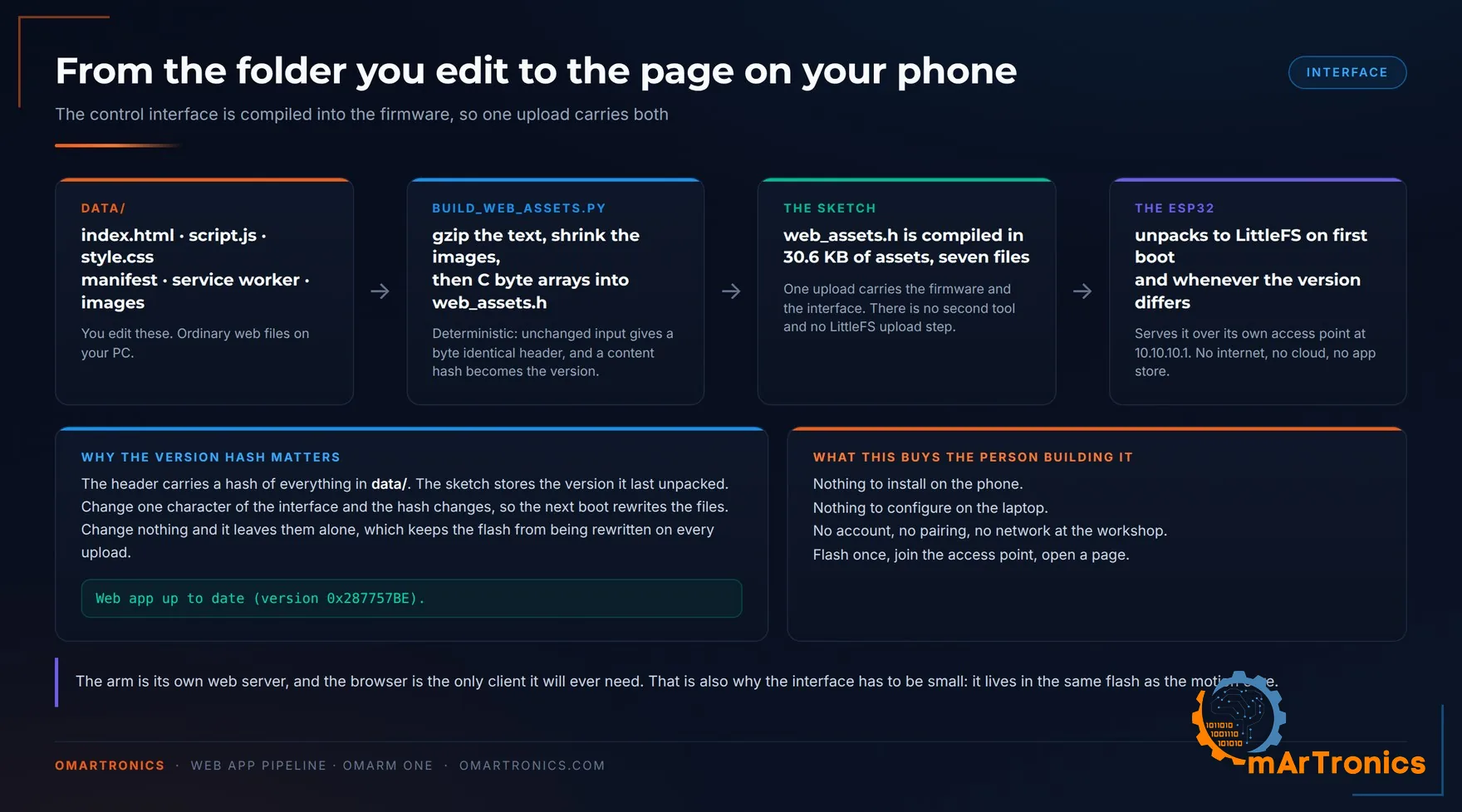
تتكون الواجهة من سبعة ملفات عادية في المجلد data/ بجوار برنامج Arduino: صفحة HTML واحدة، وسكربت واحد، وملف أنماط (Stylesheet) واحد، وملف Manifest، وService Worker، وصورتان. يحوّلها السكربت build_web_assets.py إلى web_assets.h، وهو ملف ترويسة بلغة C يدمجه المترجم (Compiler) في البرنامج الثابت. يضغط السكربت الملفات النصية بـ gzip، ويقلّص صورتي PNG إلى لوحة من 255 لونًا، ويخزن كل ملف على هيئة مصفوفة بايتات بلغة C. وعند الإقلاع الأول يفكّ برنامج Arduino حزمها إلى نظام ملفات ESP32 ويقدّمها من هناك.
بعد الترجمة (Compile)، يبلغ حجم برنامج Arduino كاملًا 1,058,099 بايت، أي 80 بالمئة من قسم التطبيق في ESP32 البالغ 1.25 MB. وتشغل الواجهة المحزومة 31 KB منه: 12.4 KB من النصوص المضغوطة بـ gzip و18.2 KB من صور PNG.
التحقق من الإصدار هو الجزء الذي سأحتفظ به في أي مشروع مماثل. يحمل web_assets.h قيمة تجزئة (Hash) لكل محتويات data/، ويتذكر برنامج Arduino قيمة التجزئة التي فكّ حزمها آخر مرة. غيّر حرفًا واحدًا في الواجهة فتتغير قيمة التجزئة، ويعيد الإقلاع التالي كتابة الملفات. وإن لم تغير شيئًا فلا يمس ذاكرة الفلاش.
Web app up to date (version 0x287757BE).
هذا السطر في سجل الإقلاع يعني أن الصفحة في متصفحك تطابق البرنامج الثابت الذي يقف خلفها. كما تُغني هذه الطريقة عن خطوة رفع نظام الملفات المنفصلة.
حدود الأمان
لنقطة الوصول كلمة مرور ثابتة مُدمجة في برنامج Arduino (Sketch)، ونقطة النهاية /api/command بلا أي نوع من المصادقة. أي شخص ضمن مدى الإشارة اللاسلكية ينضم إلى الشبكة يستطيع إرسال الأوامر إلى الذراع. والطلبات عبر المصادر المختلفة (Cross-Origin، أي الطلبات التي ترسلها إلى الذراع صفحةٌ محمّلة من موقع آخر) مسموح بها أيضًا. لذلك تستطيع أي صفحة مفتوحة مسبقًا في متصفح متصل أن ترسل أوامر إلى الذراع كذلك. على طاولة العمل لا مشكلة في ذلك. أما في غرفة مليئة بالناس فالأمر مختلف، لذا غيّر كلمة المرور قبل أن تأخذ هذه الذراع إلى أي مكان عام، وأبقِ مفتاح تغذية السيرفوهات في متناول يد أقرب شخص إليها.
أما الاتصالات الصادرة فلا يوجد منها شيء على الإطلاق. لا تحمّل الواجهة أي شبكة توصيل محتوى (CDN)، ولا أي خادم خطوط، ولا أي نقطة نهاية للتحليلات، ولهذا تعمل والذراع موضوعة على طاولة في قبو. ولن يكون على تلك الشبكة إنترنت تصل إليه أصلًا.
10. الاختبار والتحقق
خمسة اختبارات، بالترتيب الذي أجريها به. الأول يختبر مواصفات الحمولة.
اختبار الحمولة
حسبتُ نطاق الحمولة قبل البناء، كي يكون لهذا الاختبار توقعٌ مسبق قد يثبت خطؤه. القسم 4 يتوقع ما يلي.
| الاختبار | نصف القطر | الحمولة المستمرة المتوقعة، 6 V | عند عزم التوقف | 5 V للمقارنة |
|---|---|---|---|---|
| الفحص الاسمي | 300 mm | 325 g | 830 g | 219 g |
| فحص الحد الأقصى | 300 mm | الحد الأقصى 250 g يستهلك 57.6 % من عزم التوقف | لا ينطبق | سيحتاج إلى 65.6 %، أي فوق الحد |
| الحافة القصوى | 370 mm | 252 g | 661 g | 167 g |
| الامتداد الكامل | 485 mm | 175 g | 488 g | 110 g |
الإجراء. حدّد نصف قطر العمل بعلامة على الطاولة، مقيسًا أفقيًا من محور القاعدة. زِن جسم الاختبار على ميزان مطبخ، وسجّل الكتلة المقيسة، ولا تقرّبها لصالحك. أرسل إلى الذراع أمرًا بوضعية تضع نقطة الإمساك على العلامة والذراع ممدودة جيدًا، ثم أغلق القابض وارفع. بعد ذلك اتركها على حالها ستين ثانية، والمس غلاف سيرفو الكتف. الدفء متوقع. أما إذا لم تستطع إبقاء إصبعك على الغلاف، فالمفصل قد تجاوز حد التحميل المستمر أيًا كان ما تحمله الذراع. ويحوّل مقياس الحرارة بالأشعة تحت الحمراء ذلك إلى رقم يمكنك تدوينه.

ما يُعدّ نجاحًا: أن ترفع الذراع الكتلة، وتثبت على الوضعية دون أن تهبط، وأن يبقى غلاف سيرفو الكتف قابلًا للمس بعد دقيقة. الهبوط تحت الحمل هو الفشل المثير للاهتمام، لأنه يعني إما أن السيرفو تجاوز ميزانية عزم الدوران المتاحة له، وإما أن مقعد أحد المحامل مرتخٍ. والحالتان مختلفتان في الإحساس. هبوط العزم ناعم ومتواصل؛ أما المحمل المرتخي فيعطيك قفزة، أو طقّة، أو وضعية تنحرف عندما تدفع الذراع جانبيًا دفعة خفيفة.
القياس على ذراعي: حملت الذراع 325 g عند 300 mm، وهي القيمة المتوقعة كاملة، ولم يسخن سيرفو الكتف. احتاج جزء واحد إلى تعديل. فقد تآكلت أسنان المحزّز في ذراع السيرفو (Horn) البلاستيكي عند الكتف، وبدأ المفصل ينزلق. يعمل الكتف والقاعدة الآن بأذرع سيرفو من الألومنيوم بمحزّز 25T، وهي مدرجة في جدول المشتريات في القسم 6.
مقارنة اختيارية عند 5 V: الكتل نفسها وأنصاف الأقطار نفسها. توقّع حمولة أقل بنحو الثلث (219 g مقابل 325 g عند 300 mm). وعند 5 V يحتاج الحد الأقصى 250 g إلى 65.6 % من عزم التوقف، فيخفق في قاعدة 63 %. القسم 6 يشرح لماذا لا يتجاوز جهد خط تغذية السيرفوهات 6 V.
أربعة اختبارات أخرى قبل أن تعدّ الذراع منتهية
مدى كل مفصل. حرّك كل مفصل ببطء عبر مداه والذراع مسنودة، واقترب من الطرفين بحذر. الطرف عند 0 درجة ليس فضاءً حرًا: هناك تنثني الذراع على نفسها حتى تستند إلى مصدّاتها الميكانيكية، والبرنامج الثابت (Firmware) سيُصدر هذا الأمر فعلًا، لأن حدوده الوحيدة هي المدى الكامل للسيرفو من 0 إلى 180. لذا فمعيار النجاح أن يتحرك كل مفصل بسلاسة حتى أول تلامس، لا أن يجتاز المدى من 0 إلى 180 دون عائق. توقف عند أول تلامس، وتراجع قليلًا، وسجّل الزاوية. ثم قارنها بنموذج CAD: المفصل الذي يتوقف قبل حده المرسوم بفارق كبير يكون ذراع السيرفو (Horn) فيه عادةً مُركّبًا بإزاحة سنّ واحدة من أسنان المحزّز.
قابلية التكرار. ثبّت قلمًا في القابض، وألصق ورقة على الطاولة تحته، وعلّم الذراع وضعية واحدة يلامس فيها رأس القلم الورقة. ثم بدّل بين حركتين: انتقل إلى HOME، ثم عُد إلى الوضعية وسجّل النقطة؛ وانتقل إلى وضعية ثانية في الجهة البعيدة من مساحة العمل، ثم عُد وسجّل النقطة. عشر نقاط لكل اتجاه، تُقاس في مستوى الورقة فقط. يفرض النطاق الميت (Dead Band) للسيرفو حدًا أدنى قدره 0.27 درجة على النتيجة، وهو ما يعادل دائرة Ø 2.3 mm عند أقصى مدى للوصول. تجمّعُ نقاطٍ بهذا الحجم يعني أن الذراع تعمل عند حدها الفيزيائي. أما التجمّع الأوسع من ذلك بكثير فسببه ميكانيكي: جلبة مرتخية، أو محمل غير مستقر تمامًا في مقعده، أو برغي ذراع السيرفو بدأ يرتخي. وظهور تجمّعين منفصلين، واحد لكل اتجاه اقتراب، يعني وجود خلوص (Backlash). القياس على ذراعي: عشر محاولات اقتراب من كل جهة وقعت جميعها داخل حد Ø 2.3 mm، وكلها نُفّذت من تطبيق الويب.

صلابة القاعدة. يفحص هذا الاختبار محامل القاعدة، واتجاه الدفع مهم. ثبّت القاعدة على الطاولة أولًا بمشبك أو بثقل، ومدّ الذراع أفقيًا، ثم اضغط إلى الأسفل على المعصم بقوة 5 N تقريبًا، أي ما يعادل علبة ممتلئة وزنها 500 g، وراقب طرف إصبع القابض. الضغط إلى الأسفل يحمّل المحمل 51110 والمحمل 6806ZZ، لأن القوة الرأسية عند مدى الوصول تولّد عزم انقلاب حول القاعدة. ثم ارفع يدك، ويجب أن يكون الانحراف مرنًا وأن يعود إلى الصفر. أما الحركة المتأرجحة التي في وسطها منطقة ميتة فتعني أن أحد المحامل غير مستقر تمامًا في مقعده، أو أن المنصة مرتخية فوق حلقة الدفع.
أما الدفع الجانبي فيختبر شيئًا آخر. فهذا الاتجاه يمر عبر مجموعة تروس J1، حيث يكون قليل من الخلوص (Backlash) أمرًا طبيعيًا لا يدل على شيء بخصوص المحامل.
الوزن. 1283 g على ميزان المطبخ، أي أكثر بنحو 80 g من مجموع أوزان المكونات في القسم 5 (نحو 1.20 kg). يستخدم سكربت التحليل القيمة المقيسة، وتبقى كل أرقام عزم الدوران والحمولة صحيحة.
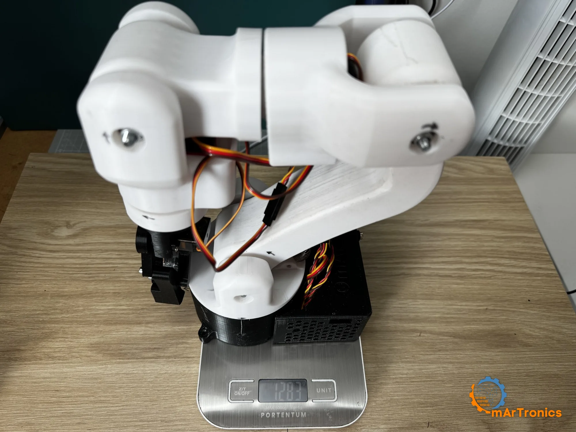
يعرض فيديو البناء في أعلى الصفحة هذه التجارب.
11. استكشاف الأخطاء وإصلاحها
هذه الأعراض مأخوذة من بناء OmArm Zero، ومن تشغيل هذا البرنامج الثابت لأول مرة على طاولة العمل.
كل المفاصل منحرفة بما يصل إلى 11 درجة، وبشكل ثابت. قيمة ثابت المذبذب لشريحة PCA9685 في الكود لديك خاطئة. كثير من الأمثلة البرمجية (Sketches) تضبطها على 27 MHz؛ بينما تنص ورقة بيانات الشريحة على 25 MHz. إذا أعطيت القيمة 27 MHz لشريحة تعمل على 25، فستطول كل نبضة بنسبة 8 بالمئة، فتصبح نبضة 1500 ميكروثانية 1620، وينحرف المفصل 11 درجة. استخدم 25 MHz ما لم تكن قد قست لوحتك بنفسك.
جميع المفاصل منحرفة قليلًا ونقطة الصفر مُزاحة. تقريب المقسّم المسبق (Prescaler)، الموضّح في القسم 8. احسب قيم العدّ الخاصة بالنبضات من قيمة المقسّم المسبق الموجودة فعلًا في الشريحة (254.3 Hz عند طلب 250 Hz)، لا من التردد الذي طلبته.
يتحرك المفصل الخطأ عند سحب أحد أشرطة التمرير. المشكلة في تعيين القنوات، لا في التوصيلات. صحّح سطر SERVO_CHANNELS، ثم أعد التحميل على اللوحة.
المفاصل ترتجف أو تطنّ وهي ثابتة. هناك سببان. إذا ظهر الارتجاف في جميع المفاصل، فهو ارتعاش (Jitter) في إشارة PWM: ولّد الإشارة بعتاد PCA9685 نفسه بدلًا من أطراف GPIO التي تعتمد على المقاطعات، ولهذا السبب توجد لوحة قيادة السيرفو في قائمة المواد (BOM). أما إذا طنّ مفصل واحد فقط، فالسبب عادةً ميكانيكي: جلبة مشدودة حتى تنحشر الشوكة، أو برغي ذراع السيرفو يحتك.
ترتخي الذراع بالكامل في نهاية التحميل على اللوحة، وتبقى مرتخية حتى تؤكد الوضعية. هذا متوقع: عملية الرفع إلى اللوحة تُعدّ انقطاعًا في التغذية. القسم 8 يتضمن التسلسل الكامل، ويشرح لماذا تطوي الذراع وتفرغ القابض أولًا.
لا يتحرك أي شيء على الإطلاق مع لوحة جديدة تمامًا. وهذا متوقع أيضًا: البرنامج الثابت يرفض التخمين. أكّد الوضعية بأحد زرّي الشريط التنبيهي في تطبيق الويب؛ القسم 9 يعرض هذا الشريط. أما مع البرنامج الثابت التسلسلي لـ ROS 2، فأرسل الأمر SETPOS عبر USB بدلًا من ذلك.
تتحرك الذراع ببطء وتثاقل، ويُعاد تشغيل ESP32 تحت الحمل. هبوط جهد التغذية: مزود طاقة أصغر من اللازم، أو غياب مكثف التخزين (Bulk Capacitor)، أو أخذ تغذية السيرفوهات من ESP32. مزود طاقة بتيار 10 A ومكثف من 1000 إلى 2200 µF على خط التغذية يعالجان السببين الأولين؛ أما الثالث فتعالجه بإعادة التوصيل، والجدول في القسم 8 يوضح الطريقة.
يسخن ESP32، ويختفي منفذ USB من حاسوبك، وترتجف الذراع من تلقاء نفسها. جهد زائد على خط تغذية السيرفوهات. يتحمل DS3240 جهدًا حتى 6.8 V، ويتحمل SG90 حتى 6 V، ويتحمل طرف V+ في PCA9685 حتى 6 V، لذا فإن ثمانية فولتات تتجاوز حدود الثلاثة جميعًا. وإغلاق الحاسوب لمنفذ USB هو دائرة حماية تؤدي عملها. القسم 4 يروي هذه الحادثة. افحص خط التغذية بجهاز القياس (Multimeter) قبل كل جلسة عمل، وضع مفتاحًا على خط تغذية السيرفوهات، حتى يكون أول تشغيل بعد أي تغيير في التوصيلات خطوة واعية ومقصودة.
يتوقف أحد المفاصل قرب أحد طرفي مداه. ذراع السيرفو (Horn) مُركّب بإزاحة سنّ واحدة من المحزّز، أو قطعة مطبوعة تعترض الحركة. أعد السيرفو إلى المنتصف كهربائيًا، ثم أعد تركيب ذراع السيرفو.
المحمل لا يدخل في مقعده. قِس قطر الثقب. ثقوب طباعة FDM تخرج أصغر من المقاس؛ والحل طباعة اختبارية للأبعاد ثم تعديل بسيط لمعامل التحجيم في برنامج التقطيع (Slicer). والخطوة 3 في القسم 7 هي الموضع المناسب لهذا الفحص بالقدمة (Caliper).
12. الأسئلة الشائعة
هل يمكنني استخدام سيرفوهات أرخص، مثل DS3218 أو MG996R؟ لا. يحتاج الكتف إلى عزم توقف قدره 37.5 kg·cm، وفي القسم 6 يتبيّن أن DS3218 يعجز حتى عن تأمين 16.10 kg·cm التي تحتاجها الذراع الفارغة ضمن قاعدة 63 بالمئة. أما MG996R بعزم 11 kg·cm فأضعف من المطلوب بكثير. وعلى AliExpress لا يكاد DS3218 يكون أرخص من DS3240 أصلًا، نحو 82 € مقابل 84 € لستة محركات، فالاستبدال يوفّر نحو يوروين ويكلّفك مفصل الكتف.
هل أشغّلها على 5 V أم 6 V؟ 6 V. هو جهد خط التغذية القياسي، لأن الحد الأقصى 250 g يحتاج إلى عزم DS3240 البالغ 41 kg·cm عند 6 V. لا ترفع الجهد أكثر من ذلك: فمحرك SG90 على الخط نفسه مصنّف لجهد 6 V كحد أقصى.
هل أحتاج إلى النابض؟ لا. كل الأرقام في هذا المقال حُسبت من دونه؛ القسم 5 يشرح ما يضيفه.
هل أحتاج إلى ROS 2 لاستخدام هذه الذراع؟ ليس في هذا الجزء. يقدّم ESP32 تطبيق الويب الخاص به عبر نقطة الوصول الخاصة به، لذا يكفيك هاتف أو حاسوب محمول. يدخل ROS 2 في الجزء 2 مع التوأم الرقمي، ويقود الذراع الحقيقية بدءًا من الجزء 3، عبر منفذ USB نفسه وأعراف البرنامج الثابت نفسها.
هل يمكنها رفع 500 g؟ ليس بشكل مستمر. عند نصف قطر 300 mm يبلغ الحد الأقصى عند عزم التوقف 830 g على خط تغذية 6 V، والسيرفو يسخن بشدة إذا عمل عند عزم التوقف. رفع 500 g لالتقاط صورة لفترة قصيرة، نعم. أما كحمولة عمل، فلا؛ فتلك آلة أخرى.
طابعتي ليست Bambu P1S. هل لا يزال بإمكاني طباعة هذه الذراع؟ تكفي أي طابعة بسرير طباعة بحدود 256 mm ودقة أبعاد جيدة. افحص دقة الثقوب قبل طباعة القاعدة، لأن مقاعد المحامل هي الأبعاد الوحيدة الحرجة فعلًا في النموذج كله.
13. ما التالي
الجزء 2 منشور الآن. يصدّر نموذج CAD إلى URDF، ويتحقق من تطابق التوأم الرقمي مع الذراع الحقيقية في RViz وGazebo (Gazebo Harmonic على ROS 2 Jazzy)، دون تحميل برنامج ثابت جديد على اللوحة. ويضيف الجزء 3 برنامج تشغيل العتاد (Hardware Driver) وتخطيط الحركة باستخدام MoveIt 2، والجزء 4 الالتقاط والوضع الموجّه بالكاميرا، والجزء 5 الإمساك بأجسام محددة بالاسم دون علامات مرجعية (Markers).
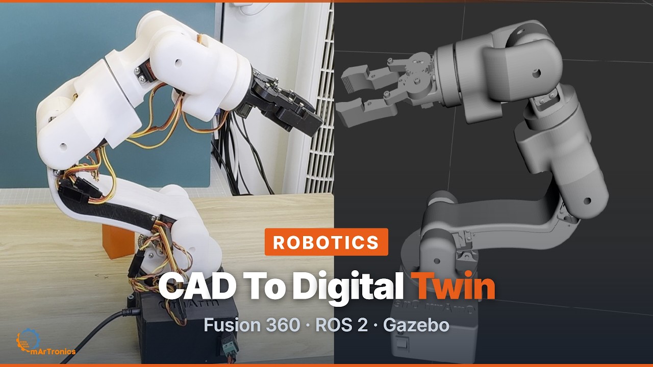
اقرأه: من Fusion 360 إلى توأم رقمي في ROS 2 · نزّل مساحة العمل: حزمة التوأم الرقمي لـ OmArm One.
إذا بنيت واحدة أو وجدت خطأً في الأرقام، فافتح بلاغًا (Issue) في مستودع GitHub. سكربت التحليل الذي أنتج هذه الأرقام يستخدم بذرة عشوائية ثابتة (Seed)، ونتائجه قابلة لإعادة الإنتاج.
المصادر
- حزمة البناء: حزمة OmArm One (سعر الإطلاق 39 € حتى 30 نوفمبر 2026، ثم 49 €): ملفات CAD، وملفات الطباعة، والبرنامج الثابت، وأدلة PDF للجزء 1 وكذلك الجزء 1.5. القائمة الكاملة موجودة في صفحة المنتج.
- البرنامج الثابت، وسكربت التحليل، والاختبارات (MIT): github.com/OmArTronics/OmArm-One. يحتوي على البرنامج الثابت لتطبيق الويب والبرنامج الثابت التسلسلي لـ ROS 2 مع اختباراتهما على جانب الحاسوب، إضافةً إلى مخططات التوصيل. ويعيد السكربت omarm_one_analysis.py حسابات التحجيم (Sizing) على نموذج الروبوت المشتق من CAD، لتتمكن من التحقق من كل رقم في هذا المقال. أما ملفات CAD فموجودة في الحزمة أعلاه.
- قياس النابض واختيار البديل: spring-rate-measurement.md في المستودع.
- OmArm Zero، السلسلة السابقة: الجزء 1.
مقارنة بين كل أذرعي الروبوتية: كيف تبني ذراعًا روبوتية بست محاور في المنزل يشرح ماذا يعني ست محاور، ويضع التصاميم الأربعة في جدول واحد، ويخبرك أيها تبني أولًا.