
This post contains affiliate links, marked with *. As an Amazon Associate I earn from qualifying purchases, at no extra cost to you. It helps keep the tutorials free.

The video loads from YouTube (Google), which may set cookies. Privacy policy
1. Why This Sensor & Introduction
The HC-SR04 is an ultrasonic distance module: two metal cylinders (the ultrasonic transducers) on a small board. One sends a burst of sound too high for you to hear, the other listens for the echo. It measures from about 2 cm to 400 cm, runs on 5 V and reports distance as the width of a single pulse. It costs about one euro, which is why it is in almost every starter kit. Typical uses are a parking assistant, a robot that stops before an obstacle, and a contactless water-level gauge. I have used it before in my Arduino radar and my obstacle-avoiding robot car.
Here it is wired to an ESP32 (a microcontroller board with built-in Wi-Fi), which shows the distance in centimeters live on a web dashboard that you open in your phone’s browser. The post also shows where the readings drift and when they are wrong, using numbers from my own test session. For an Arduino Uno version, see the Arduino ultrasonic distance sensor tutorial. The wiring is simpler there, because a 5 V board needs no divider on the Echo line.
2. How It Works
2.1 The sensing principle
Think of shouting across a canyon and counting the seconds until your voice comes back. Sound travels at a fixed speed, so the delay tells you how far away the far wall is. The HC-SR04 does the same over 2 cm to 4 m, at a pitch you cannot hear. When the ESP32 sends it a 10 µs trigger pulse, it emits eight cycles of 40 kHz sound from its transmitter. A microsecond (µs) is one millionth of a second, and 40 kHz means 40,000 vibrations per second. The sound travels through the air, hits whatever is in front of the sensor, and returns to the receiver. The sensor measures how long the round trip took.
The measured time is for a round trip: the sound travels to the object and back, so the time corresponds to twice the distance you want to know. That is why the formula divides by two. The sensor does not know the distance in centimeters; it only knows a duration. It hands you that duration as an electrical pulse and leaves the arithmetic to the ESP32. The 40 kHz frequency was chosen because it carries well through air over these short ranges and because cheap piezo transducers (ceramic elements that turn voltage into vibration and back) have their resonant frequency there.
2.2 The key equation
The sensor gives you the echo time in microseconds. The speed of sound in dry air at 20 °C is about 343 m/s, which is easier to use as 0.0343 cm per microsecond. So:
distance (cm) = (echo_time_us * 0.0343) / 2
echo_time_us is how long the Echo pin stayed high (at its “on” voltage), in microseconds, measured by the ESP32. 0.0343 converts microseconds of flight into centimeters of travel. The / 2 removes the return leg, because the pulse timed the trip out and back. The datasheet folds all of that into a shortcut, distance_cm = echo_time_us / 58, and the two agree: 1 divided by (0.0343 divided by 2) is 58.3.
Worked example: the Echo pin stays high for 1160 µs. Multiply by 0.0343 to get 39.79 cm of total sound travel, then divide by 2: 19.9 cm. The shortcut gives 1160 / 58 = 20.0 cm, the same answer within rounding.
The speed of sound rises by about 0.6 m/s per °C, roughly 0.18 % per degree, and the formula assumes 20 °C. At 30 °C the echo returns sooner, and the true distance is about 1.7 % longer than the formula reports. At 89 cm that is about 1.5 cm, more than the 9 mm spread measured in section 7. Precision setups add a temperature sensor for this reason.
2.3 Inside the module, step by step
The full chain from trigger pulse to a number on screen:
- Trigger: the ESP32 holds the Trig (trigger) pin high for 10 µs, the “start measuring” signal.
- Emit: the module fires eight cycles of 40 kHz ultrasound from the transmitter.
- Travel out: the sound crosses the gap to the object.
- Reflect: the object bounces part of the sound back toward the sensor.
- Receive: the receiver (the second metal cylinder) detects the returning echo.
- Echo pulse: the module raises the Echo pin and holds it high for exactly as long as the round trip took.
- Measure: the ESP32 times that high pulse in microseconds.
- Calculate: you apply the formula above and get the distance in centimeters.
3. Interactive Animation
The animation sends a burst, shows it travel to the object and back, and updates the distance, the echo time and the equation live as you drag the slider. Ping fires a single measurement; Auto sweep moves the object on its own.
If the animation does not load, open it in a new tab.
4. Wiring, Components & OmBlock
4.1 Bill of materials
You need an ESP32, the HC-SR04, two resistors for a voltage divider, a breadboard (a solderless board with connected rows of contacts) and jumper wires. The set costs about six to nine euros, most of it for the ESP32.
| Parts used in this project | AD · AFFILIATE LINKS | |
|---|---|---|
| ESP32 DevKit V1 Board | Dual-core microcontroller (MCU) with Wi-Fi and Bluetooth (BT), 3.3 V logic, USB | Amazon* · AliExpress |
| HC-SR04 Ultrasonic Sensor | 2-400 cm ultrasonic distance module, 5 V, 40 kHz | Amazon* · AliExpress |
| Resistor Assortment Kit | 1/4 W carbon film, incl. 1 kΩ and 2.2 kΩ for the Echo divider | Amazon* · AliExpress |
| Breadboard (830 tie-point) | Solderless prototyping board | Amazon* · AliExpress |
| Jumper Wire Set | Dupont wires with plug-in ends: male-male (M-M), male-female (M-F), female-female (F-F) | Amazon* · AliExpress |
*Affiliate links: I earn a small commission if you buy through them, at no extra cost to you.
As an Amazon Associate and AliExpress affiliate, OmArTronics earns from qualifying purchases. The price stays the same for you, and the small commission helps keep these tutorials free.
4.2 Wiring it up
The HC-SR04 has four pins: VCC, Trig, Echo and GND. Three of them are simple to connect. VCC goes to the ESP32 5 V pin, GND goes to ESP32 GND, and Trig goes to GPIO 5 (GPIO: a general-purpose input/output pin). The fourth pin, Echo, needs extra care.
Echo idles low and then pulses up to 5 V to report the distance. ESP32 inputs are 3.3 V pins, so a raw 5 V signal on GPIO 18 stresses the pin and can damage it over time. The fix is a voltage divider: two resistors in series that split the 5 V down to a safe level. R1 (1 kΩ) sits between Echo and a middle node; R2 (2.2 kΩ) sits between that node and ground. The ESP32 reads the node, where the voltage is 5 × 2.2 / (1 + 2.2) = 3.44 V.
I picked that second value by accident and kept it. Most tutorials use 1 kΩ and 2 kΩ, which gives 3.33 V. My resistor kit had no 2 kΩ. That value is not in the E12 series, the twelve standard resistor values per decade (1.0, 1.2, 1.5, 1.8, 2.2 and so on) that cheap kits are built from. The kit had 2.2 kΩ, so I used that. The node sits at 3.44 V, slightly above the 3.3 V supply but under the ESP32’s absolute maximum of 3.6 V (the voltage above which the chip can be damaged). The board has run for hours on my bench without problems. If you want to stay below 3.3 V, 2.2 kΩ for R1 and 3.3 kΩ for R2 gives 3.0 V using two values that are in standard E12 kits. Trig needs no divider: the Trig input accepts the ESP32’s 3.3 V output as a logic high (the voltage the module reads as “on”).
The full pin mapping:
| HC-SR04 pin | ESP32 pin | Wire color | Note |
|---|---|---|---|
| VCC | 5 V / VIN | red | full 5 V, not 3.3 V; some boards label this pin VIN |
| Trig | GPIO 5 | blue | 3.3 V drive is enough |
| Echo | node -> GPIO 18 | orange | through the R1/R2 divider |
| GND | GND | black | connect this first |
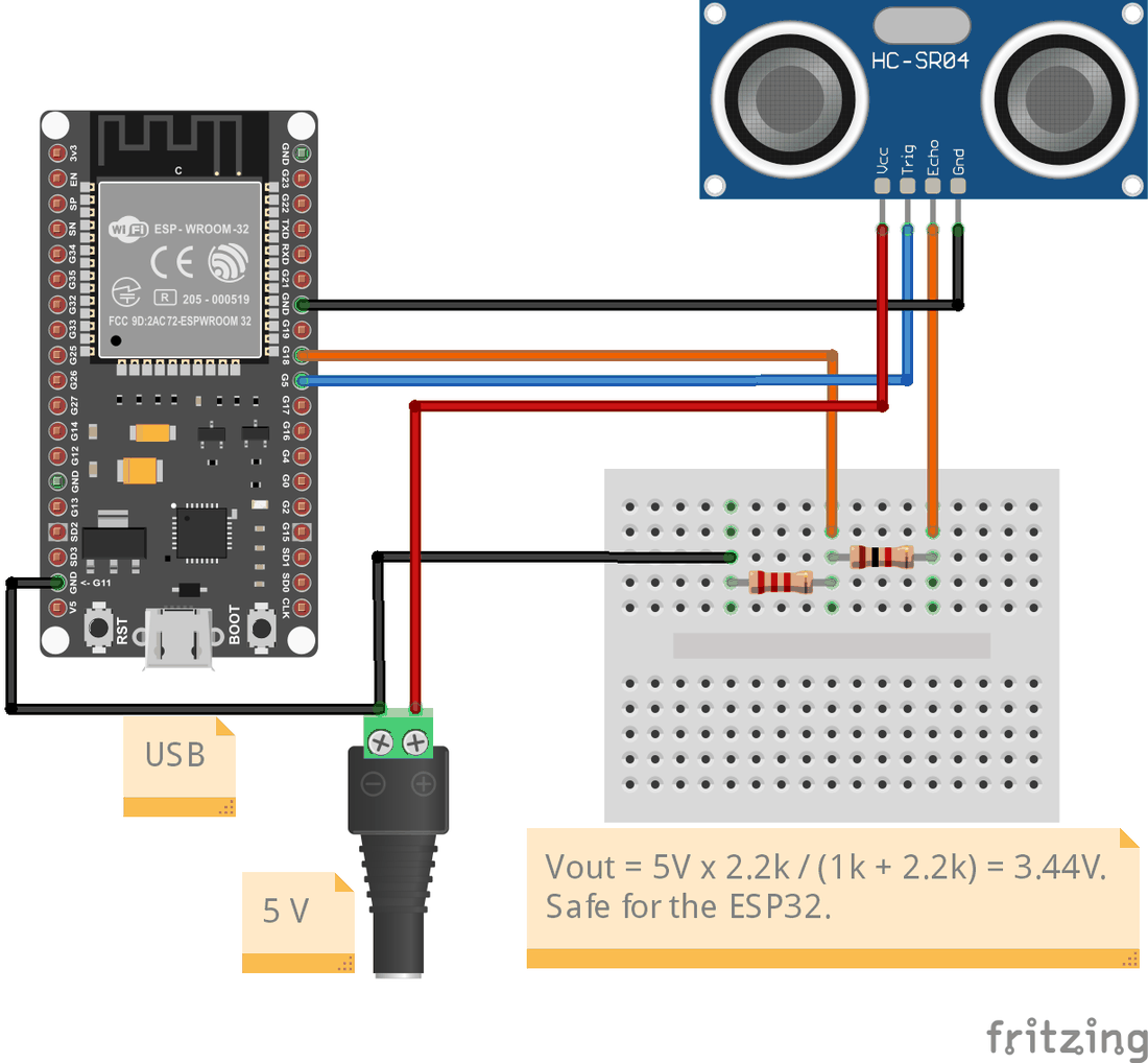
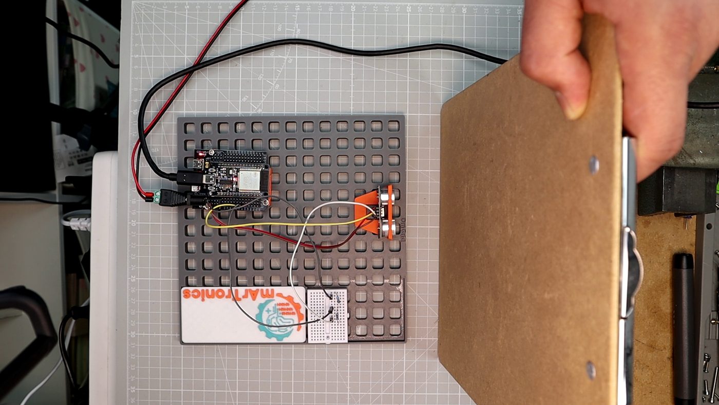
The two resistors sit in one column on the small breadboard. The 1 kΩ resistor runs from Echo down to the middle row, the 2.2 kΩ resistor from that row to ground, and the wire to GPIO 18 taps the row between them.
Wire it in this order: ground first, then VCC, then Trig, then build the divider and run the node to GPIO 18. Avoid GPIO 6 through 11, which the ESP32 uses for its flash chip (the memory that holds the program). GPIO 5 and 18 are safe.
4.3 The OmBlock enclosure
Every sensor in this series gets an OmBlock, a small 3D-printed holder that snaps into the OmGrid (a 3D-printed baseplate with a regular pattern of mounting holes). The result is a tidy bench setup instead of a loose breadboard. The same grid carries the OmArm Zero robot arm, where the system started. OmBlock-HC-SR04 has two 16 mm openings for the transducers and a rear channel for the four wires, and it sits next to OmBlock-ESP32 and OmBlock-Power. Print it in PLA (the standard printing plastic) at 0.2 mm layer height (the thickness of each printed layer) with no supports. The STL file (the 3D model that you load into a slicer, the program that prepares the print) is linked in section 9.
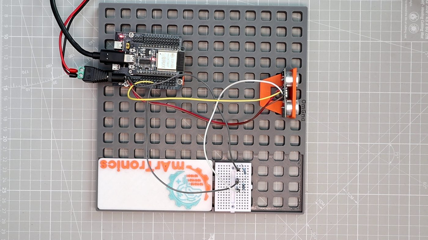
Printed in orange PLA, it holds the two transducers perpendicular to the target. A sensor tilted away from a smooth surface can lose the echo, because the sound reflects to the side instead of back to the receiver. Before the OmBlock I was propping the module against a battery pack and wondering why readings dropped out.
4.4 Notes before you power on
Check these before you power on:
- Give the sensor a real 5 V supply; on 3.3 V the range shrinks and readings get noisy.
- Never wire Echo straight to a GPIO without the divider.
- If every reading comes back as 0 or nonsense, check that VCC and GND are not swapped and that the divider node reaches GPIO 18.
- Aim the sensor at a flat, hard surface; soft or angled targets scatter the echo and cause dropouts (readings where no echo comes back, see section 7).
5. Test Code
Before the web dashboard, get a plain reading over the Serial Monitor (the Arduino IDE window that shows the text the board sends over USB). It proves that the wiring and the divider are right. The logic is short: trigger a ping, time the Echo pulse, convert to centimeters, reject anything outside 2 to 400 cm.
The test sketch (an Arduino program) is a single file without extra tabs (additional source files that the IDE shows side by side). Open it in the Arduino IDE (the editor that compiles and uploads the code) and upload it. All settings you might change (pins, read interval, calibration offset) sit in a labeled block at the top:
/*
 * HC-SR04 Ultrasonic Distance — Test Sketch
 * OmArTronics · Project 01 · 2026-07-25 · MIT License
 *
 * Prints distance in cm over Serial at 115200 baud.
 * Wiring: Trig -> GPIO 5, Echo -> GPIO 18 through a 1k/2.2k divider (5V -> 3.44V),
 *         VCC -> 5V, GND -> GND.  See wiring.md.
 *
 * Single file — just open in the Arduino IDE and upload. Change pins below.
 */

// ===== Settings (edit these) =====
#define TRIG_PIN            5       // ESP32 GPIO 5  -> HC-SR04 Trig
#define ECHO_PIN            18      // ESP32 GPIO 18 <- Echo via 1k/2.2k divider
#define READING_INTERVAL_MS 60      // datasheet suggests >= 60 ms between pings
#define ECHO_TIMEOUT_US     25000   // ~430 cm round trip; pulseIn gives up after this
#define SERIAL_BAUD         115200
#define SOUND_CM_PER_US     0.0343f // speed of sound at 20 C, cm per microsecond
#define DIST_MIN_CM         2.0f    // datasheet minimum
#define DIST_MAX_CM         400.0f  // datasheet maximum
#define CALIBRATION_OFFSET  0.0f    // cm added after conversion (tune vs a ruler)
#define CALIBRATION_SCALE   1.0f    // multiply reading (1.0 = no change)
// =================================

// One measurement. Returns distance in cm, or NAN if the reading is invalid.
float readDistanceCm() {
  // 10 us trigger pulse tells the module to fire an 8-cycle 40 kHz burst.
  digitalWrite(TRIG_PIN, LOW);
  delayMicroseconds(2);
  digitalWrite(TRIG_PIN, HIGH);
  delayMicroseconds(10);
  digitalWrite(TRIG_PIN, LOW);

  // pulseIn measures how long Echo stays HIGH, in microseconds.
  // It returns 0 if no echo arrives before the timeout.
  unsigned long echo_us = pulseIn(ECHO_PIN, HIGH, ECHO_TIMEOUT_US);
  if (echo_us == 0) return NAN;                 // timeout: nothing in range

  // Convert time of flight to distance (divide by 2 for the round trip).
  float cm = (echo_us * SOUND_CM_PER_US) / 2.0f;
  cm = cm * CALIBRATION_SCALE + CALIBRATION_OFFSET;

  // Reject readings outside the datasheet range.
  if (cm < DIST_MIN_CM || cm > DIST_MAX_CM) return NAN;
  return cm;
}

void setup() {
  Serial.begin(SERIAL_BAUD);
  pinMode(TRIG_PIN, OUTPUT);
  pinMode(ECHO_PIN, INPUT);
  digitalWrite(TRIG_PIN, LOW);
  delay(50);
  Serial.println(F("HC-SR04 test ready. Distance in cm:"));
}

void loop() {
  float cm = readDistanceCm();
  if (isnan(cm)) {
    Serial.println(F("-- out of range / no echo --"));
  } else {
    Serial.print(cm, 1);
    Serial.println(F(" cm"));
  }
  delay(READING_INTERVAL_MS);
}
pulseIn(ECHO_PIN, HIGH, ECHO_TIMEOUT_US) blocks until Echo goes high and then low. It returns the high time in microseconds, or 0 if nothing comes back before the timeout. The / 2.0f is the round-trip correction from section 2. isnan(cm) catches both the timeout and the out-of-range case with one check, so the loop prints a clean “out of range” line instead of a meaningless number. Without an echo, most modules hold Echo high for about 38 ms. The 25 ms timeout (ECHO_TIMEOUT_US) ends the wait before that, so this sketch prints the out-of-range line. The pulseIn sketch in my Arduino Uno tutorial keeps the default timeout of one second and prints about 650 cm in the same case.
Expected Serial Monitor output at 115200 baud (the speed of the USB serial link in bits per second), moving a hand toward the sensor:
HC-SR04 test ready. Distance in cm:
34.2 cm
28.9 cm
19.9 cm
11.3 cm
-- out of range / no echo --
If the Serial output is wrong, the wiring is wrong. Fix it here before you move on to the dashboard.
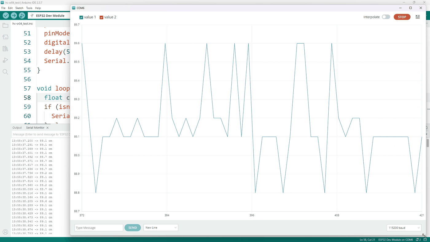
In the screenshot the wall does not move, yet the Serial Plotter (the Arduino IDE’s chart view of the same Serial data) draws a jagged line. The variation between 88.7 and 89.6 cm is sensor noise. Section 7 puts numbers on it.
6. Live Web-Plotter
6.1 How it works
The sketch hc-sr04_plotter.ino turns the ESP32 into a Wi-Fi access point and a small web server. The access point opens its own Wi-Fi network for other devices to join, and the web server answers requests from a browser. Your phone joins the network “OmArTronics-HC-SR04”, opens http://10.10.10.1, and the dashboard polls (repeatedly requests) a JSON endpoint five times a second. A JSON endpoint is a URL that returns the current values as JSON, a plain-text data format. It needs no internet connection and no app: the dashboard is stored in the firmware (the program you upload to the ESP32), and the ESP32 serves it itself.
6.2 Dashboard features
The dashboard shows one large live number and a rolling chart of the last 100 readings that scales its own axis. Cards show the running minimum, maximum, average and total count. A snapshot button saves the chart as a PNG. An export button downloads the buffered readings as CSV (comma-separated values, a text format that opens in Excel or LibreOffice). A reset button clears the statistics on the ESP32. A dot in the corner turns red and the value blanks if three polls in a row fail; the dashboard then reconnects on its own.
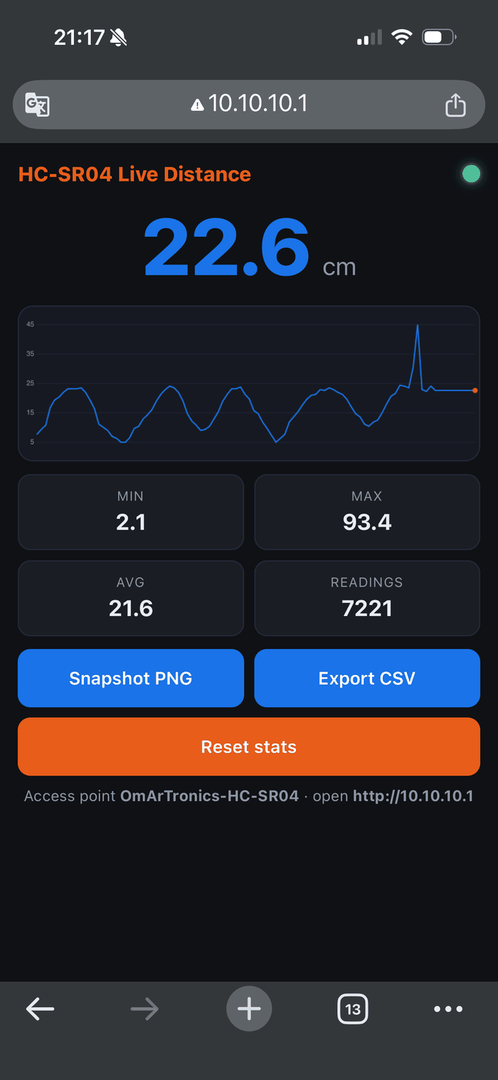
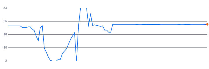
The snapshot and CSV buttons are the main reason for the dashboard. Several measurements in section 7 come from a CSV exported with the CSV button. The snapshot button produces the image below, straight from the browser canvas (the chart’s drawing area).
6.3 Firmware
The dashboard sketch reuses the measurement code of the test sketch, wraps it in running statistics, and adds three JSON endpoints. The loop never calls delay(); it answers browser requests on every pass and takes a reading only when READING_INTERVAL_MS has elapsed.
The whole dashboard (HTML, CSS and JavaScript, the three parts of a web page) sits in the sketch as text constants (string literals) and is served with server.send_P(). Each constant is marked PROGMEM, a keyword that keeps the data in flash on boards that would otherwise copy it into RAM (the working memory for variables). On the ESP32, data declared const stays in flash anyway, so PROGMEM only keeps the code compatible with other Arduino boards. send_P() reads the dashboard from flash in small chunks and sends it over the network connection, so it is never copied into RAM as a whole. The dashboard travels with the firmware in one upload.
/*
* HC-SR04 Live Web-Plotter — ESP32 Access Point, single-sketch build
* OmArTronics · Project 01 · MIT License
*
* ONE upload. That is the whole point of this version.
*
* The dashboard (HTML, CSS, JavaScript) is embedded in the sketch as PROGMEM
* strings, so it travels with the firmware into flash. No LittleFS, no data/
* folder, no IDE plugin, no second upload step. The earlier build kept the
* dashboard on a LittleFS partition and every single failure I hit was in that
* handover: wrong partition scheme, Serial Monitor holding the port, the IDE 2.x
* uploader plugin refusing to appear. The dashboard is 6.9 KB. Flash is 4 MB.
* Carrying it in the sketch costs nothing and removes an entire class of bugs.
*
* Steps:
* 1) Upload this sketch
* 2) Join WiFi "OmArTronics-HC-SR04", password "ultrasonic"
* 3) Open http://10.10.10.1
*
* Wiring: TRIG -> GPIO 5, ECHO -> GPIO 18 through a 1k / 2.2k divider (3.44 V
* at the node), VCC -> 5V, GND -> GND. See the blog post for the schematic.
*
* Boot log runs at 115200 baud.
*/
#include <WiFi.h>
#include <WebServer.h>
#include <ArduinoJson.h>
// ===== Settings (edit these) =====
#define TRIG_PIN 5
#define ECHO_PIN 18
#define READING_INTERVAL_MS 60
#define ECHO_TIMEOUT_US 25000
#define SERIAL_BAUD 115200
#define SOUND_CM_PER_US 0.0343f
#define DIST_MIN_CM 2.0f
#define DIST_MAX_CM 400.0f
#define CALIBRATION_OFFSET 0.0f
#define CALIBRATION_SCALE 1.0f
#define WIFI_SSID "OmArTronics-HC-SR04"
#define WIFI_PASS "ultrasonic"
// =================================
WebServer server(80);
// --- Running statistics ---
float g_last = NAN, g_min = NAN, g_max = NAN;
double g_sum = 0.0;
unsigned long g_count = 0;
unsigned long g_lastReadMs = 0;
// ============================================================================
// The dashboard. Everything between R"rawname( and )rawname" is copied verbatim
// into flash, so you can edit it like a normal web file. The only rule: the
// content must never contain the closing sequence )rawname".
// ============================================================================
static const char INDEX_HTML[] PROGMEM = R"HTMLPAGE(<!DOCTYPE html>
<html lang="en">
<head>
<meta charset="utf-8">
<meta name="viewport" content="width=device-width, initial-scale=1">
<meta name="theme-color" content="#0f1115">
<link rel="manifest" href="manifest.json">
<title>HC-SR04 Live Plotter</title>
<link rel="stylesheet" href="style.css">
</head>
<body>
<header>
<h1>HC-SR04 Live Distance</h1>
<span id="dot" class="dot" title="connection"></span>
</header>
<main>
<section class="live">
<div id="value">--</div><div class="unit">cm</div>
</section>
<canvas id="chart" width="720" height="240" aria-label="Rolling distance chart"></canvas>
<section class="cards">
<div class="card"><div class="lbl">MIN</div><div id="min" class="num">--</div></div>
<div class="card"><div class="lbl">MAX</div><div id="max" class="num">--</div></div>
<div class="card"><div class="lbl">AVG</div><div id="avg" class="num">--</div></div>
<div class="card"><div class="lbl">READINGS</div><div id="count" class="num">0</div></div>
</section>
<section class="btns">
<button id="snap">Snapshot PNG</button>
<button id="csv">Export CSV</button>
<button id="reset" class="warn">Reset stats</button>
</section>
<p class="hint">Access point <b>OmArTronics-HC-SR04</b> · open <b>http://10.10.10.1</b></p>
</main>
<script src="script.js"></script>
</body>
</html>
)HTMLPAGE";
static const char STYLE_CSS[] PROGMEM = R"CSSPAGE(
*{box-sizing:border-box;margin:0;padding:0}
body{background:#0f1115;color:#e8ecf2;font-family:-apple-system,Segoe UI,Roboto,Arial,sans-serif;max-width:820px;margin:0 auto;padding:14px}
header{display:flex;align-items:center;justify-content:space-between;margin-bottom:10px}
h1{font-size:clamp(16px,4vw,22px);color:#E85D1A;font-weight:800}
.dot{width:14px;height:14px;border-radius:50%;background:#c23b22;box-shadow:0 0 8px #c23b22;transition:.3s}
.dot.ok{background:#39c07a;box-shadow:0 0 8px #39c07a}
.live{display:flex;align-items:baseline;gap:8px;justify-content:center;margin:8px 0}
#value{font-size:clamp(44px,16vw,84px);font-weight:800;color:#1a73e8;transition:color .2s}
.unit{font-size:clamp(16px,5vw,26px);color:#8b95a6}
canvas{width:100%;height:auto;background:#161922;border:1px solid #232838;border-radius:12px;display:block;margin:8px 0}
.cards{display:grid;grid-template-columns:repeat(4,1fr);gap:8px;margin:10px 0}
.card{background:#1a1d23;border:1px solid #232838;border-radius:10px;padding:10px 8px;text-align:center}
.lbl{font-size:10.5px;color:#8b95a6;letter-spacing:.5px}
.num{font-size:clamp(15px,4.5vw,20px);font-weight:700;margin-top:3px}
.btns{display:flex;gap:8px;flex-wrap:wrap;margin:6px 0}
button{flex:1 1 130px;min-height:46px;border:none;border-radius:10px;background:#1a73e8;color:#fff;font-size:14px;font-weight:600;cursor:pointer}
button.warn{background:#E85D1A}
button:active{transform:translateY(1px)}
.hint{font-size:12px;color:#8b95a6;text-align:center;margin-top:8px}
@media(max-width:460px){.cards{grid-template-columns:repeat(2,1fr)}}
)CSSPAGE";
static const char SCRIPT_JS[] PROGMEM = R"JSPAGE(
// HC-SR04 live plotter — polls the ESP32 JSON API, draws a rolling chart.
var MAX_POINTS = 100;
var series = []; // {t, v} rolling buffer for chart + CSV
var fails = 0;
var dot = document.getElementById('dot');
var elV = document.getElementById('value');
var elMin = document.getElementById('min'), elMax = document.getElementById('max');
var elAvg = document.getElementById('avg'), elCount = document.getElementById('count');
var cv = document.getElementById('chart'), cx = cv.getContext('2d');
// The sensor resolves to about 3 mm, so printing more than one decimal would be
// inventing precision the hardware does not have. The CSV export rounds the same way.
function fmt(x){ return (x===null||x===undefined||isNaN(x))?'--':(+x).toFixed(1); }
function setConnected(ok){
dot.classList.toggle('ok', ok);
if(!ok){ elV.textContent='--'; elV.style.color='#c23b22'; }
else { elV.style.color='#1a73e8'; }
}
function poll(){
fetch('/api/data',{cache:'no-store'}).then(function(r){return r.json();}).then(function(d){
fails = 0; setConnected(true);
elV.textContent = fmt(d.value);
elMin.textContent = fmt(d.min); elMax.textContent = fmt(d.max);
elAvg.textContent = fmt(d.avg); elCount.textContent = d.count||0;
if(d.value!==null && d.value!==undefined && !isNaN(d.value)){
series.push({t:d.timestamp_ms, v:+d.value});
if(series.length>MAX_POINTS) series.shift();
draw();
}
}).catch(function(){
fails++; if(fails>=3) setConnected(false);
});
}
function draw(){
var W=cv.width, H=cv.height, pad=28;
cx.clearRect(0,0,W,H);
cx.strokeStyle='#232838'; cx.lineWidth=1;
for(var i=0;i<=4;i++){ var y=pad+(H-2*pad)*i/4; cx.beginPath(); cx.moveTo(pad,y); cx.lineTo(W-6,y); cx.stroke(); }
if(series.length<2) return;
var vals=series.map(function(p){return p.v;});
var lo=Math.min.apply(null,vals), hi=Math.max.apply(null,vals);
if(hi-lo<1){ hi+=1; lo-=1; } // avoid flat-line divide by zero
cx.fillStyle='#8b95a6'; cx.font='11px sans-serif'; cx.textAlign='right';
for(var k=0;k<=4;k++){ var val=hi-(hi-lo)*k/4; var yy=pad+(H-2*pad)*k/4; cx.fillText(val.toFixed(0),pad-4,yy+3); }
cx.strokeStyle='#1a73e8'; cx.lineWidth=2; cx.beginPath();
series.forEach(function(p,idx){
var x=pad+(W-pad-6)*idx/(MAX_POINTS-1);
var y=pad+(H-2*pad)*(1-(p.v-lo)/(hi-lo));
idx?cx.lineTo(x,y):cx.moveTo(x,y);
});
cx.stroke();
var last=series[series.length-1];
var lx=pad+(W-pad-6)*(series.length-1)/(MAX_POINTS-1);
var ly=pad+(H-2*pad)*(1-(last.v-lo)/(hi-lo));
cx.fillStyle='#E85D1A'; cx.beginPath(); cx.arc(lx,ly,4,0,7); cx.fill();
}
function download(name, url){
var a=document.createElement('a'); a.href=url; a.download=name; a.click();
}
document.getElementById('snap').onclick=function(){
download('hc-sr04_'+Date.now()+'.png', cv.toDataURL('image/png'));
};
document.getElementById('csv').onclick=function(){
var rows=['timestamp_ms,distance_cm'];
series.forEach(function(p){ rows.push(p.t+','+p.v.toFixed(1)); });
download('hc-sr04_'+Date.now()+'.csv', 'data:text/csv,'+encodeURIComponent(rows.join('\n')));
};
document.getElementById('reset').onclick=function(){
fetch('/api/reset',{method:'POST'}).then(function(){ series=[]; draw(); });
};
if('serviceWorker' in navigator){ navigator.serviceWorker.register('sw.js').catch(function(){}); }
setConnected(false);
setInterval(poll, 200);
poll();
)JSPAGE";
// Lets the phone install the page as an app icon. Optional, costs 200 bytes.
static const char MANIFEST_JSON[] PROGMEM = R"MANPAGE({
"name":"HC-SR04 Live Plotter","short_name":"HC-SR04","start_url":"/",
"display":"standalone","background_color":"#0f1115","theme_color":"#0f1115"}
)MANPAGE";
// The service worker only registers itself. Caching the shell would fight the
// live data, and the pages already ship inside the firmware.
static const char SW_JS[] PROGMEM = R"SWPAGE(
self.addEventListener('install', function(){ self.skipWaiting(); });
self.addEventListener('activate', function(e){ e.waitUntil(self.clients.claim()); });
)SWPAGE";
// ============================================================================
// Sensor
// ============================================================================
float readSensor() {
digitalWrite(TRIG_PIN, LOW);
delayMicroseconds(2);
digitalWrite(TRIG_PIN, HIGH);
delayMicroseconds(10);
digitalWrite(TRIG_PIN, LOW);
unsigned long echo_us = pulseIn(ECHO_PIN, HIGH, ECHO_TIMEOUT_US);
if (echo_us == 0) return NAN;
float cm = (echo_us * SOUND_CM_PER_US) / 2.0f;
cm = cm * CALIBRATION_SCALE + CALIBRATION_OFFSET;
if (cm < DIST_MIN_CM || cm > DIST_MAX_CM) return NAN;
return cm;
}
void updateStats(float cm) {
g_last = cm;
if (isnan(g_min) || cm < g_min) g_min = cm;
if (isnan(g_max) || cm > g_max) g_max = cm;
g_sum += cm;
g_count++;
}
// ============================================================================
// HTTP handlers
// ============================================================================
void handleData() {
StaticJsonDocument<256> doc;
doc["sensor"] = "HC-SR04";
doc["unit"] = "cm";
// Raw values, not rounded. The dashboard and its CSV export round to one
// decimal; anyone reading the API directly gets what the sensor actually produced.
if (isnan(g_last)) doc["value"] = nullptr; else doc["value"] = g_last;
if (isnan(g_min)) doc["min"] = nullptr; else doc["min"] = g_min;
if (isnan(g_max)) doc["max"] = nullptr; else doc["max"] = g_max;
doc["avg"] = g_count ? (g_sum / g_count) : 0.0;
doc["count"] = g_count;
doc["timestamp_ms"] = millis();
String out; serializeJson(doc, out);
server.send(200, "application/json", out);
}
void handleStatus() {
StaticJsonDocument<256> doc;
doc["uptime_s"] = millis() / 1000;
doc["clients"] = WiFi.softAPgetStationNum();
doc["readings"] = g_count;
doc["free_heap"] = ESP.getFreeHeap();
String out; serializeJson(doc, out);
server.send(200, "application/json", out);
}
void handleReset() {
g_min = g_max = g_last = NAN;
g_sum = 0.0; g_count = 0;
server.send(200, "application/json", "{\"ok\":true}");
}
// send_P streams straight out of flash, so the page never occupies RAM.
void handleIndex() { server.send_P(200, "text/html", INDEX_HTML); }
void handleCss() { server.send_P(200, "text/css", STYLE_CSS); }
void handleJs() { server.send_P(200, "application/javascript", SCRIPT_JS); }
void handleManifest() { server.send_P(200, "application/json", MANIFEST_JSON); }
void handleSw() { server.send_P(200, "application/javascript", SW_JS); }
// Phones and laptops probe a handful of URLs to decide whether a network has
// internet. Answering them with the dashboard makes the captive-portal popup
// open it directly, which saves typing the IP on a phone.
void handleNotFound() { handleIndex(); }
// ============================================================================
void setup() {
Serial.begin(SERIAL_BAUD);
delay(300);
pinMode(TRIG_PIN, OUTPUT);
pinMode(ECHO_PIN, INPUT);
digitalWrite(TRIG_PIN, LOW);
Serial.println(F("\n--- OmArTronics HC-SR04 Live Plotter ---"));
Serial.printf("Dashboard in flash: %u bytes (html+css+js)\n",
(unsigned)(sizeof(INDEX_HTML) + sizeof(STYLE_CSS) + sizeof(SCRIPT_JS)));
WiFi.mode(WIFI_AP);
WiFi.softAPConfig(IPAddress(10,10,10,1), IPAddress(10,10,10,1), IPAddress(255,255,255,0));
WiFi.softAP(WIFI_SSID, WIFI_PASS);
Serial.print(F("AP up: ")); Serial.println(WiFi.softAPIP());
Serial.print(F("SSID: ")); Serial.println(F(WIFI_SSID));
server.on("/", HTTP_GET, handleIndex);
server.on("/index.html", HTTP_GET, handleIndex);
server.on("/style.css", HTTP_GET, handleCss);
server.on("/script.js", HTTP_GET, handleJs);
server.on("/manifest.json", HTTP_GET, handleManifest);
server.on("/sw.js", HTTP_GET, handleSw);
server.on("/api/data", HTTP_GET, handleData);
server.on("/api/status", HTTP_GET, handleStatus);
server.on("/api/reset", HTTP_POST, handleReset);
server.onNotFound(handleNotFound);
server.begin();
Serial.println(F("Web server started. Open http://10.10.10.1"));
}
void loop() {
server.handleClient();
unsigned long now = millis();
if (now - g_lastReadMs >= READING_INTERVAL_MS) {
g_lastReadMs = now;
float cm = readSensor();
if (!isnan(cm)) updateStats(cm);
}
}
6.4 The dashboard source
Editing HTML inside a C string is unpleasant, so the three files also live as normal web files in web_src/ next to the sketch. They mirror the PROGMEM blocks: copy changes from one to the other. fmt() in the JavaScript rounds every displayed value to one decimal. The API (the JSON endpoints) returns the raw value, which looks like 21.35175 because it comes out of a floating-point division (arithmetic with decimal numbers). Five decimals from a sensor rated at 3 mm resolution is invented precision, so the dashboard shows 21.4. The CSV export also rounds to one decimal (p.v.toFixed(1) in the code); only the API returns the raw number.
6.5 One upload, and the two days it cost me to get there
The obvious way to put a web dashboard on an ESP32 is LittleFS, a small filesystem for the flash. The sketch goes into program flash, the web files go into a separate filesystem partition, and the board serves them from there. The partition scheme sets how the flash is divided between program and file storage. That is how my robot arm firmware works, and it is what almost every tutorial shows. So that is how I built this one.
Then I flashed it, joined the access point, opened 10.10.10.1, and got a page telling me the filesystem was mounted and contained zero files. The sensor readings were correct. 10.10.10.1/api/data returned live distances. Only the dashboard was missing, because the second upload had never happened.
Getting that second upload to work is where the time went. The IDE 1.8 menu item, Tools > ESP32 Sketch Data Upload, does not exist in IDE 2.x. Its replacement, arduino-littlefs-upload, is a .vsix plugin file that you copy into .arduinoIDE/plugins/ by hand. On several 2.3.x builds it then does not appear in the command palette (the IDE’s search box for commands). For this project I used IDE 2.3.7 and later 2.3.10. Even when it works, it fails silently if the Serial Monitor is holding the COM port (the USB serial connection the IDE uses), and changing the partition scheme afterwards erases everything you flashed. I built a browser upload form into the sketch as a workaround. It worked, but the tutorial’s second step was still “now upload five more files”.
Then I asked myself why the dashboard was in a filesystem at all. It is 6.9 KB. The flash is 4 MB. Put it in the sketch.
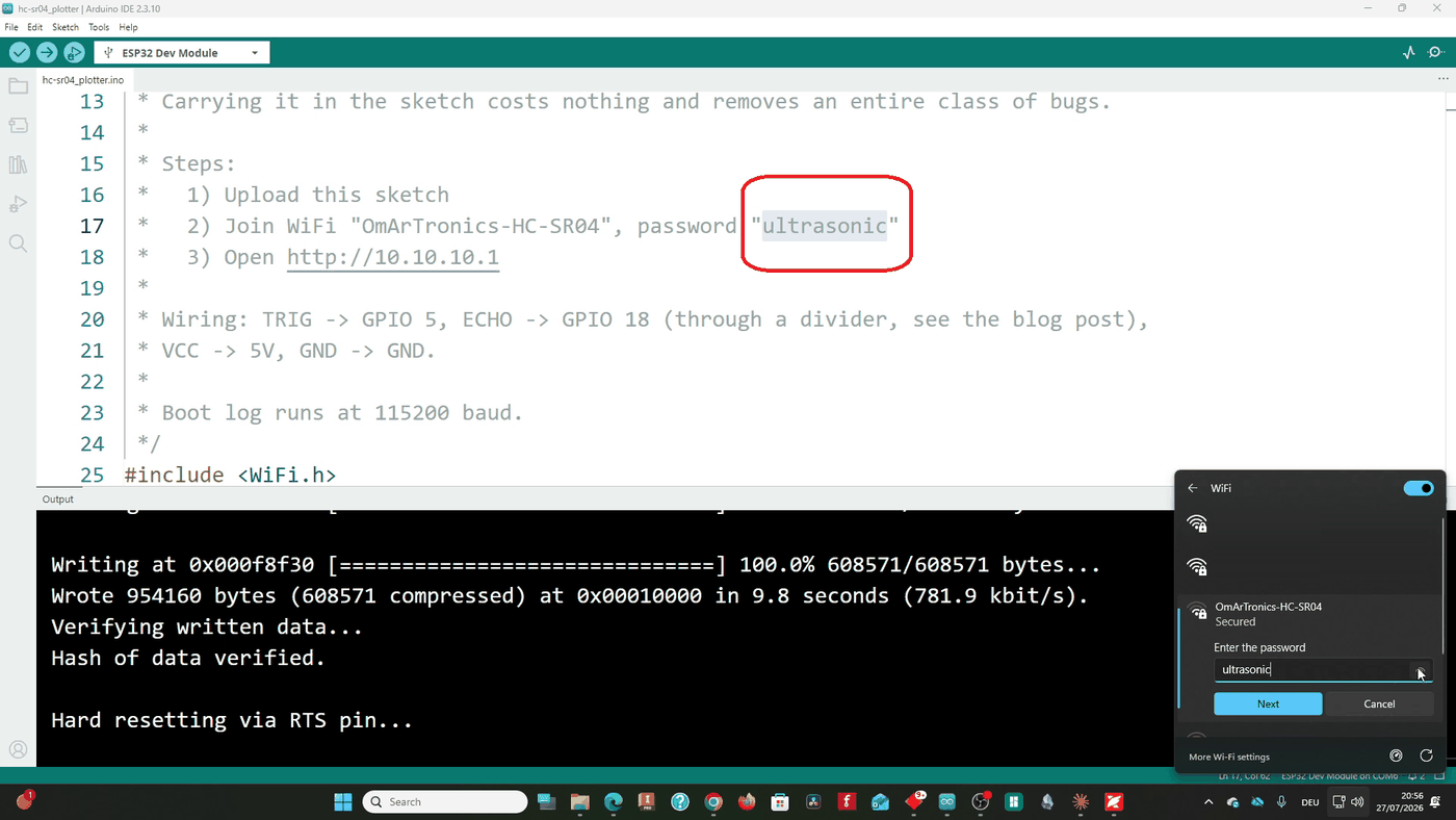
So the dashboard now lives in PROGMEM and the whole procedure is:
- Upload the sketch.
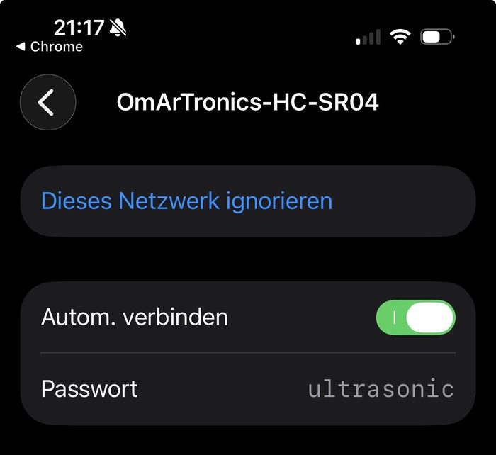
- Join the Wi-Fi network “OmArTronics-HC-SR04”, password ultrasonic.
- Open http://10.10.10.1.
The board came up on the first try.
A filesystem is the better choice for a dashboard larger than a few tens of kilobytes, for dashboard updates without recompiling, or for logs stored on the device. For a single-page dashboard that ships with the firmware, a filesystem adds complexity you do not need. Every sensor in this series will use the PROGMEM version.
7. Limitations & Edge Cases
This is the part I care most about in this series: what the datasheet claims, and what the sensor on my desk measured. The numbers below come from the Serial Plotter, the CSV export and the dashboard statistics of a real session.
A motionless target still produces a jagged line. The datasheet lists 0.3 cm resolution and best-case accuracy of ±3 mm. I pointed the sensor at a wall roughly 89 cm away, left everything untouched, and watched the Serial Plotter. Over 24 consecutive readings in 1.55 seconds the values ran from 88.7 to 89.6 cm. The median (the middle value of the sorted readings) was 89.1 cm. The standard deviation (how far a reading typically sits from the mean, the average of all readings) was 1.8 mm, and the peak-to-peak spread (lowest to highest reading) was 9 mm. That spread is three times the resolution the datasheet advertises, and the target did not move.
The same shows up closer in. A 2.4 second window at about 8 cm gave a mean of 7.67 cm with a 6 mm spread. Nothing is broken; this is the normal noise of a 40 kHz burst timed in microseconds.
Single-sample outliers occur, and they are large. An outlier is a single reading far away from its neighbors. In a 100-sample export the reading jumped from 22.3 cm to 32.7 cm and back to 23.5 cm within two samples, while the target had not moved that far. On the phone screenshot the same shows up as a lone spike to 45 cm in an otherwise smooth curve. If your project acts on distance, take the median of three or five readings instead of trusting a single one.
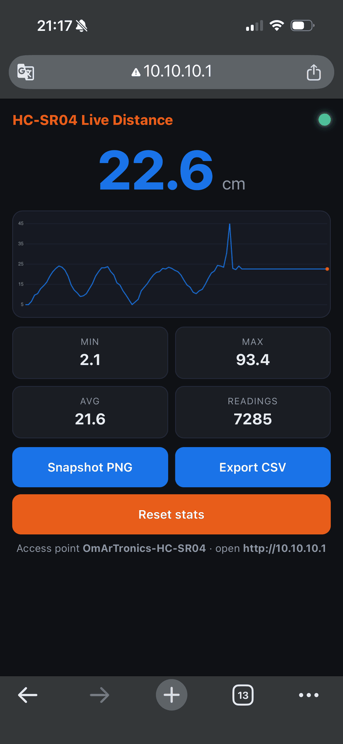
The 2 cm floor is enforced twice. The session’s minimum was 2.1 cm, but the sketch itself throws away anything under DIST_MIN_CM, which is set to 2.0. So the floor I measured comes partly from my own filter and partly from the module. The physical reason: the transducer is still ringing from its own burst when the echo from a very close object arrives, and the module cannot tell the two apart.
Long range is untested. The largest value in the session was 93.4 cm, and an earlier run peaked at 101.4 cm. The datasheet says 400 cm; I did not test targets that far away.
The Serial log and the CSV use different sampling rates. The 24 Serial readings of the 89 cm test took 1.55 s, an average of 67.5 ms per reading against a configured interval of 60 ms. Most of the extra time is the echo flight, about 5 ms at 89 cm. Single gaps between the timestamps range from 32 to 94 ms (median 78 ms), because the IDE stamps each line when it arrives over USB, and USB delivers lines in small bursts. The CSV exported from the dashboard has its samples a median of 205 ms apart, because that file holds what the browser polled, not every reading the ESP32 took. Check which of the two you have before using either as a timing reference.
Not measured yet (expected from the datasheet and the physics):
- Soft or angled targets: foam, curtains and anything hit at an angle scatter the echo. Expect dropouts rather than wrong-but-plausible numbers.
- Beam width around 15 degrees: the sensor reports the nearest object inside a cone, not along a thin line. A doorframe at the edge of the cone can be reported instead of the target.
- Temperature drift: the fixed 0.0343 constant assumes 20 °C. Above 20 °C the sensor reads short by about 0.18 % per degree (see section 2.2).
- Cross-talk: two HC-SR04 units firing at once can hear each other. Stagger their triggers if you use more than one.
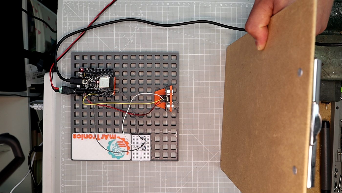
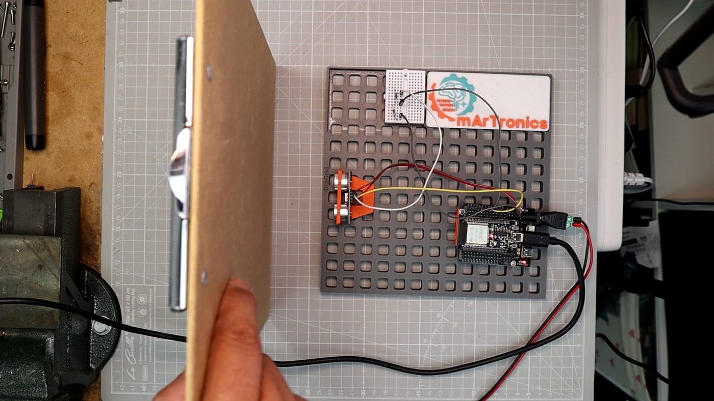
Held perpendicular to the sensor, a board like this is the easy case. Tilted as in the photo, most of the burst is expected to reflect away from the sensor, and the reading should drop out.
8. Summary & Next Sensor
Five points for your next build:
- Divide by two, always. The Echo pulse times the trip out and back. cm = echo_us * 0.0343 / 2, or the datasheet shortcut echo_us / 58.
- The divider is not optional. Echo swings to 5 V, the ESP32 is a 3.3 V part. 1 kΩ / 2.2 kΩ gives 3.44 V on the node, under the 3.6 V absolute maximum, and both values are in standard E12 resistor kits.
- A single reading is not reliable. A motionless wall at 89 cm gave a 9 mm spread, and a single sample jumped 10 cm and came back. Median-filter three to five readings before you act on the number.
- Keep a small dashboard in PROGMEM. A 6.9 KB dashboard does not need a LittleFS partition, a plugin and a second upload. A filesystem pays off for dashboards of a few tens of kilobytes or for logs on the device (section 6.5).
- Plot your sensor, do not print it. The false-echo spike in section 7 is invisible in a scrolling Serial Monitor and obvious on a chart.
Quick Reference Card
| Spec | HC-SR04 |
|---|---|
| Sensor type | Ultrasonic distance, 40 kHz time-of-flight (distance from the travel time of the echo) |
| Interface | Digital: 10 µs trigger pulse in on Trig, echo pulse width out on Echo |
| Supply | 5 V, about 15 mA; the Echo output needs a divider for 3.3 V microcontrollers such as the ESP32 |
| Range (datasheet) | 2 to 400 cm, 0.3 cm resolution, ±3 mm best case |
| Range (measured here) | 2.1 to 101.4 cm tested; 9 mm peak-to-peak spread on a motionless target at 89 cm |
| Update rate | 60 ms minimum cycle per datasheet (about 16 readings/s); measured here: 67.5 ms per reading over Serial, dashboard polls every 200 ms |
| Beam | About 15 degree cone; reports the nearest object in the cone |
| Best for | Flat, hard, perpendicular targets: walls, boards, liquid surfaces, parking assistants |
| Avoid if | Targets are soft, tilted, tiny or closer than 2 cm, or you need millimeter accuracy |
The next sensor in the series also senses at a distance, with different physics: a PIR sensor that detects the infrared radiation of warm bodies instead of an echo. If you want the same ESP32 to do more in the meantime, the OmArm Zero build puts six servos and a web interface on the same board.
9. Downloads & Links
| File | What it is |
|---|---|
| hc-sr04_test.ino | Serial test sketch from section 5 |
| hc-sr04_plotter.ino | Sketch for section 6 with the dashboard built in, one upload |
| web_src/ | The dashboard as editable HTML, CSS and JS |
| schematic.svg | Wiring diagram with the Echo divider |
| OmBlock HC-SR04.stl | 3D-printable sensor holder for the OmGrid |
| hc-sr04_animation.html | The interactive animation from section 3 |
| HC-SR04_Guide_EN.pdf | Printable workbench guide: quick facts, wiring, full code, troubleshooting |
| HC-SR04_Guide_AR.pdf | The same guide in Arabic |
| HC-SR04_QuickStart_EN.pdf | One-page quick start card for the bench |
| HC-SR04_QuickStart_AR.pdf | The quick start card in Arabic |
Firmware is MIT licensed, so you can use it in any project. The CAD files and documentation are for personal use.
Datasheet: HC-SR04 (SparkFun mirror)
Parts and kits: OmArTronics shop; the affiliate box in section 4.1 links the individual components.
Next in the series: PIR motion sensor HC-SR501 (coming soon).
Get everything in one free download: the HC-SR04 Sensor Lab Package. It has the firmware, wiring files, the full OmGrid STL set, both PDF guides, the 24-slide deck, the animation and the raw measured data from this post.
Video walkthrough: watch the 8-minute build on YouTube.