

Quick Summary
How to use the L298N dual H-bridge motor driver with Arduino. Covers the pinout, wiring for one or two DC motors, direction and speed control with PWM, and power supply setup. Includes tested Arduino code for common motor control setups.
DC motors need more current than an Arduino pin can supply, so you need a motor driver to sit between the two. The L298N dual H-bridge is one of the most common modules for this job. In this tutorial, I cover how H-bridge motor control works, how to wire the L298N to an Arduino, and how to write code for direction and speed control with PWM. I also go over power supply setup, troubleshooting, and frequently asked questions.
What this tutorial covers
- What the L298N motor driver is, what an H-bridge does, and why you need a motor driver in the first place.
- The full L298N pinout, including ENA, ENB, IN1 through IN4, motor outputs, and power terminals.
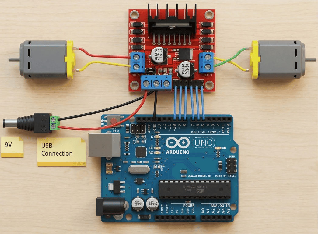
- Wiring the L298N to an Arduino and one or two DC motors with a proper external power supply.
- How to write Arduino code that controls motor direction with digitalWrite() and motor speed with analogWrite() using PWM.
- Testing, tuning, and troubleshooting your motor driver setup so it works reliably.
- How the L298N compares with other popular Arduino motor driver options like the Arduino Motor Shield and L293D shield.
What Is the L298N Motor Driver?
The L298N is a dual H-bridge motor driver IC mounted on a breakout board. Because it has two independent channels, it lets you control two DC motors at the same time, setting both the direction and speed of each motor from an Arduino or any other microcontroller. The module handles motor supply voltages from 5 V to 35 V and delivers up to 2 A of continuous current per channel, which is enough for most small to medium hobby motors. If you are new to Arduino, our What is Arduino guide is a good place to start before getting into motor control.
The L298N module is popular in robotics projects because it is cheap, easy to find, and works well for beginners. You’ll find it in countless Arduino robot cars, including our own obstacle-avoiding robot car and Bluetooth-controlled robot car projects.
How an H-Bridge Works
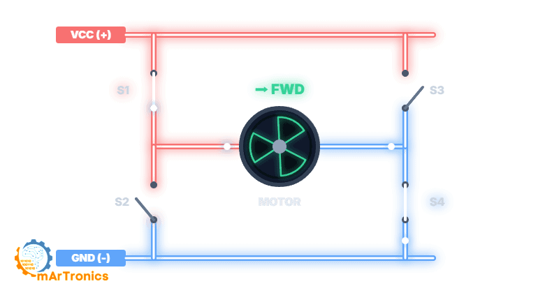
An H-bridge is a circuit made up of four switches arranged in an H-shaped pattern around a motor. When you open and close different pairs of switches, you make current flow through the motor in either direction, which controls whether it spins forward or backward.
Forward Direction
When switches S1 and S4 are closed while S2 and S3 remain open, current flows from the power supply through the motor in one direction, causing it to spin forward.
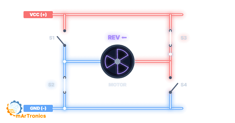
Reverse Direction
Conversely, when switches S2 and S3 are closed while S1 and S4 remain open, current flows in the opposite direction, reversing the motor.
Speed Control with PWM
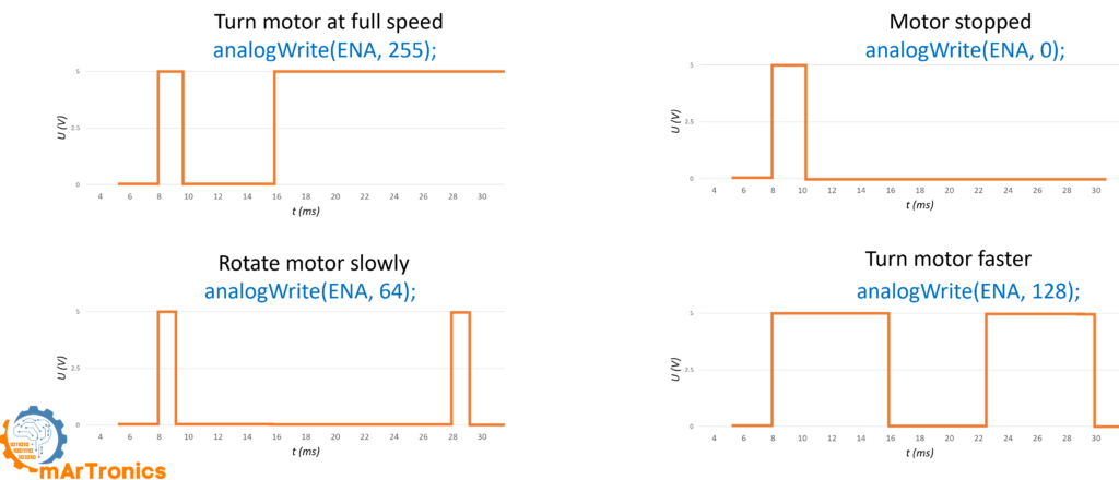
Pulse Width Modulation (PWM) is the technique you use to control motor speed. Instead of supplying a constant voltage, the Arduino rapidly switches the enable pin on and off. The ratio of on-time to off-time, called the duty cycle, determines the average voltage the motor receives. A 50 percent duty cycle, for example, delivers roughly half the supply voltage, so the motor spins slower. In contrast, a 100 percent duty cycle delivers the full voltage for maximum speed. On the L298N module, you apply PWM signals to the ENA and ENB enable pins.
L298N Pinout Explained
The L298N breakout board has several groups of pins and terminals, so before you connect anything, you need to understand each one.

Motor output terminals (OUT1, OUT2, OUT3, OUT4): These screw terminals connect directly to your DC motors. OUT1 and OUT2 drive Motor A, while OUT3 and OUT4 drive Motor B.
Power terminals (+12V, GND, +5V): The +12V terminal accepts the external motor power supply, which can range from 5 V to 35 V depending on your motors. GND is the common ground shared between the motor supply, the L298N logic, and the Arduino. The +5V terminal can either output 5 V when the onboard voltage regulator is enabled via a jumper, or alternatively accept a 5 V logic supply when the jumper is removed and motor voltage exceeds 12 V.
Enable and Input Pins
Enable pins (ENA, ENB): These pins control whether each motor channel is active and at what speed. When you install a jumper cap on ENA or ENB, that motor runs at full speed whenever its direction pins are set. If you remove the jumper and connect ENA or ENB to an Arduino PWM pin instead, you get full speed control through analogWrite().
Input pins (IN1, IN2, IN3, IN4): These four digital input pins control the direction of each motor. IN1 and IN2 control Motor A, while IN3 and IN4 control Motor B. So if you set IN1 HIGH and IN2 LOW, Motor A spins forward. Conversely, reversing those values spins it backward, and setting both to the same state (both LOW or both HIGH) stops the motor.
Components Needed (BOM)
Gather the following components before you start wiring. If you are new to Arduino development, check our Arduino programming basics tutorial to get your IDE and board set up first.
| Component | Quantity | Notes |
|---|---|---|
| Arduino Uno (or compatible board) | 1 | Any Arduino with PWM-capable digital pins will work |
| L298N dual H-bridge motor driver module | 1 | The red breakout board with screw terminals |
| DC motor (3 V–12 V hobby motor) | 1 or 2 | TT gear motors for robot cars work well |
| External power supply for motors | 1 | Battery pack or bench supply matching your motor voltage (e.g. 4x AA batteries, 7.4 V LiPo, or 9 V–12 V adapter) |
| Jumper wires (M-F type) | ~10 | For connecting L298N pins to Arduino header pins |
| Breadboard (optional) | 1 | Helpful for organizing connections during prototyping |
| Robot chassis and wheels (optional) | 1 set | Needed if you are building a robot car project |
L298N Wiring with Arduino
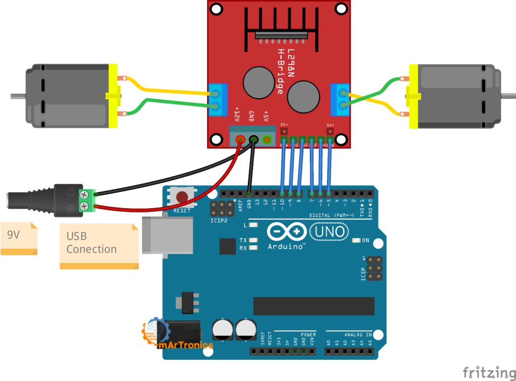
Once you have the components, the table below shows the complete wiring between the L298N module and the Arduino Uno for controlling two DC motors with independent speed and direction.
| L298N Pin | Function | Arduino Pin | Notes |
|---|---|---|---|
| ENA | Motor A speed (PWM) | D10 (PWM) | Remove the jumper cap from ENA to enable PWM speed control |
| IN1 | Motor A direction input 1 | D9 | Set HIGH or LOW to control direction |
| IN2 | Motor A direction input 2 | D8 | Set HIGH or LOW to control direction |
| IN3 | Motor B direction input 1 | D7 | Set HIGH or LOW to control direction |
| IN4 | Motor B direction input 2 | D6 | Set HIGH or LOW to control direction |
| ENB | Motor B speed (PWM) | D5 (PWM) | Remove the jumper cap from ENB to enable PWM speed control |
| +12V (VCC) | Motor power supply positive | — | Connect to your external battery or supply positive terminal (5 V–35 V; typically 6 V–12 V for most robot projects) |
| GND | Common ground | GND | Critical: Connect the L298N GND to both the external supply ground AND the Arduino GND |
| +5V | Onboard 5 V regulator output | — | With the onboard jumper installed, this outputs 5 V. Can optionally power the Arduino, but most beginners should power the Arduino separately via USB |
Power Supply and Safety
Power mistakes are the number one cause of problems in L298N projects, so follow these guidelines to keep your setup running safely.
Always use an external power supply for motors. DC motors draw far more current than the Arduino 5V pin can safely provide, so if you try to power motors directly from the Arduino, you will see voltage drops, erratic behavior, and possibly permanent damage to your board. Use a separate battery pack or power adapter connected to the L298N +12V terminal.
Connect a common ground. The Arduino GND, the L298N GND, and the negative terminal of your external motor power supply must all be connected together. Without a common ground, the L298N cannot read the Arduino’s logic signals correctly, so your motors may behave unpredictably or not move at all.
Match your power supply to your motors. Check the voltage rating on your DC motors and then choose a supply that matches. For typical TT gear motors used in robot cars, a 4xAA battery pack (6 V) or a 7.4 V LiPo works well. The L298N module itself supports motor voltages from 5 V up to 35 V.
Voltage Regulator, Drop, and Noise
Understand the onboard 5V regulator. The L298N board has a built-in voltage regulator with a jumper cap. When the jumper is installed and you supply 7 V–12 V to the +12V terminal, the +5V pin on the board outputs a regulated 5 V that you can optionally use to power your Arduino (connect it to the Arduino 5V pin, not Vin). However, if your motor supply exceeds 12 V, you should remove this jumper to protect the regulator, and you will need to supply 5 V logic power to the +5V pin separately.
Expect voltage drop. The L298N uses BJT-based switching internally, so about 1.4 V to 2 V is lost as heat across the driver. If you supply 6 V, for example, your motors actually receive around 4 V to 4.6 V. Because of this, plan your supply voltage with this drop in mind.
Watch for motor noise. DC motors generate electrical noise and voltage spikes, especially when they start or reverse. If your Arduino resets unexpectedly when the motor turns on, that noise is likely the cause. Make sure power connections are solid, consider adding a 100 nF ceramic capacitor across each motor terminal, and always keep the motor power supply separate from the Arduino power supply.
Arduino Code: Controlling Two DC Motors
Once your wiring is complete, upload the following sketch to your Arduino. This code demonstrates forward motion, stopping, and reverse for two DC motors at half speed. If you need a refresher on uploading sketches, see our Arduino programming basics guide.
Full sketch: two motor control
/**
 * L298N Motor Driver - Two DC Motor Control
 * Author: Omar Draidrya
 * Website: omartronics.com
 *
 * Controls forward, stop, and reverse for two DC motors
 * using the L298N dual H-bridge with PWM speed control.
 */

#define IN1 9    // Motor A direction pin 1
#define IN2 8    // Motor A direction pin 2
#define IN3 7    // Motor B direction pin 1
#define IN4 6    // Motor B direction pin 2
#define ENA 10   // Motor A speed control (PWM)
#define ENB 5    // Motor B speed control (PWM)

void setup() {
  // Set all motor control pins as outputs
  pinMode(IN1, OUTPUT);
  pinMode(IN2, OUTPUT);
  pinMode(IN3, OUTPUT);
  pinMode(IN4, OUTPUT);
  pinMode(ENA, OUTPUT);
  pinMode(ENB, OUTPUT);

  // Start with motors stopped
  digitalWrite(IN1, LOW);
  digitalWrite(IN2, LOW);
  digitalWrite(IN3, LOW);
  digitalWrite(IN4, LOW);
}

void loop() {
  // --- Move both motors FORWARD at half speed ---
  digitalWrite(IN1, HIGH);
  digitalWrite(IN2, LOW);
  digitalWrite(IN3, HIGH);
  digitalWrite(IN4, LOW);
  analogWrite(ENA, 128);   // Motor A at ~50% speed
  analogWrite(ENB, 128);   // Motor B at ~50% speed
  delay(2000);

  // --- STOP both motors ---
  digitalWrite(IN1, LOW);
  digitalWrite(IN2, LOW);
  digitalWrite(IN3, LOW);
  digitalWrite(IN4, LOW);
  delay(2000);

  // --- Move both motors BACKWARD at half speed ---
  digitalWrite(IN1, LOW);
  digitalWrite(IN2, HIGH);
  digitalWrite(IN3, LOW);
  digitalWrite(IN4, HIGH);
  analogWrite(ENA, 128);
  analogWrite(ENB, 128);
  delay(2000);

  // --- STOP both motors ---
  digitalWrite(IN1, LOW);
  digitalWrite(IN2, LOW);
  digitalWrite(IN3, LOW);
  digitalWrite(IN4, LOW);
  delay(1000);
}
Code Walkthrough
Pin definitions (lines 10-15): Six pins are defined using #define. IN1 and IN2 control Motor A direction, while IN3 and IN4 control Motor B direction. ENA and ENB control the speed of each motor through PWM. I chose pins 10 and 5 for ENA and ENB because they support PWM on the Arduino Uno.
setup() function: First, the code configures all six pins as outputs using pinMode(). Then, it sets all direction pins LOW so both motors start in a stopped state. Some Arduino boards leave pins in an unpredictable state after reset, so this step matters.
Forward motion: the code sets IN1 HIGH and IN2 LOW, which tells the H-bridge to drive Motor A forward. Similarly, IN3 HIGH and IN4 LOW drives Motor B forward. Next, the analogWrite(ENA, 128) call sends a PWM signal with a duty cycle of about 50 percent (128 out of 255), so the motor runs at roughly half speed. After that, the code waits 2 seconds.
Stop state: Then, the code sets all four direction pins LOW. When both inputs of a motor channel are the same, the motor stops. The enable pins do not need to change here because the direction logic already prevents any current flow.
Backward motion: For the reverse pass, the code sets IN1 LOW and IN2 HIGH, reversing Motor A. IN3 goes LOW and IN4 goes HIGH to reverse Motor B. The speed stays at 128 for half speed.
Single Motor Example
If you only need to control one DC motor, use Motor A (IN1, IN2, ENA) and leave Motor B disconnected. The sketch below shows a minimal single-motor example that cycles through forward, stop, reverse, and stop at adjustable speed.
/**
 * L298N - Single DC Motor Control
 * Author: Omar Draidrya
 * Website: omartronics.com
 *
 * Drives one DC motor forward, stops, reverses, and stops.
 * Uses Motor A channel only (IN1, IN2, ENA).
 */

#define IN1  9   // Motor A direction pin 1
#define IN2  8   // Motor A direction pin 2
#define ENA  10  // Motor A speed (PWM)

void setup() {
  pinMode(IN1, OUTPUT);
  pinMode(IN2, OUTPUT);
  pinMode(ENA, OUTPUT);
  digitalWrite(IN1, LOW);
  digitalWrite(IN2, LOW);
}

void loop() {
  // Forward at 75 % speed
  digitalWrite(IN1, HIGH);
  digitalWrite(IN2, LOW);
  analogWrite(ENA, 191);
  delay(2000);

  // Stop
  digitalWrite(IN1, LOW);
  digitalWrite(IN2, LOW);
  delay(1000);

  // Reverse at 50 % speed
  digitalWrite(IN1, LOW);
  digitalWrite(IN2, HIGH);
  analogWrite(ENA, 128);
  delay(2000);

  // Stop
  digitalWrite(IN1, LOW);
  digitalWrite(IN2, LOW);
  delay(1000);
}
This sketch uses only three Arduino pins because you only need one motor channel. Connect IN1 to pin 9, IN2 to pin 8, and ENA (with the jumper removed) to pin 10. The second motor channel remains unused and does not need any wiring.
Direction Logic Reference Table
| IN1 | IN2 | Motor A Behavior |
|---|---|---|
| HIGH | LOW | Spins forward |
| LOW | HIGH | Spins backward |
| LOW | LOW | Stops (coast) |
| HIGH | HIGH | Stops (brake) |
Test and Tune Your Setup
Start with one motor. Disconnect Motor B and test only Motor A first, because this makes it easier to spot wiring or code problems. Once Motor A works correctly, then connect Motor B.
Start with one motor. Disconnect Motor B and test only Motor A first. This makes it easier to spot wiring or code problems. Once Motor A works correctly, then connect Motor B.
Verify the direction. Upload the code and check whether the motor spins forward during the forward section. If it spins the wrong way, swap the two motor wires in the screw terminal, or swap the IN1 and IN2 pin assignments in your code.
Start with low PWM values. Rather than jumping to analogWrite(ENA, 255), start at a low value like 80 or 100. A slow-spinning motor is safer during testing and easier to observe. Keep in mind, though, that very low PWM values (below about 50-70) may not generate enough voltage to overcome the motor’s internal friction, and the motor may stall or hum without spinning.
Speed Tuning and Observation
Listen and observe. If a motor hums but does not spin, that usually means the PWM voltage is too low or something is mechanically jammed. When the motor briefly twitches and then the Arduino resets, that points to a power supply issue. Spinning in only one direction suggests a wiring or code error on one of the direction pins.
Listen and observe. A motor that hums but does not spin usually means the PWM voltage is too low or something is mechanically jammed. If the motor briefly twitches and then the Arduino resets, that points to a power supply issue. Spinning in only one direction suggests a wiring or code error on one of the direction pins.
Common Problems and Troubleshooting
Even experienced builders run into issues with motor drivers. Here are the most common problems and how to solve them.
Motor does not spin at all. First, check that your external power supply is connected to the +12V and GND terminals and that you turned it on. Then, verify that you removed the ENA or ENB jumpers and connected them to a PWM pin on the Arduino. Also, make sure the analogWrite value is high enough (try 200 or 255). Finally, double-check that the direction pins are not both HIGH or both LOW unintentionally.
Wiring and Connection Issues
Only spins in one direction. This usually means one of the two direction pins (IN1/IN2 or IN3/IN4) is not properly connected, or the pin assignment in the code is wrong. To troubleshoot, test each direction pin individually with a simple digitalWrite HIGH or LOW and observe the result.
Motor is weak or slow. Because the L298N drops about 1.4 V to 2 V internally, a 5 V or 6 V power supply may leave the motor with as little as 3.5 V to 4 V. Try a higher voltage supply. Also check that the PWM value in analogWrite() is set high enough.
Power and Thermal Issues
Arduino resets when motor starts. This is almost always a power problem. The motor draws a large inrush current at startup, which causes the supply voltage to dip and the Arduino to reset. Make sure you are using a separate power supply for the motors and that the Arduino gets its own power through USB or a dedicated adapter. A large electrolytic capacitor (100 uF to 470 uF) across the motor power supply can also help smooth things out. And of course, confirm that your common ground connection is solid.
Pin and Connection Errors
Wrong PWM pin. Not all Arduino pins support PWM. On the Arduino Uno, only pins 3, 5, 6, 9, 10, and 11 support analogWrite(). If you connect ENA or ENB to a non-PWM pin, the motor will either be fully on or fully off with no speed control. Look for the PWM symbol (~) printed next to the pin numbers on your board.
Missing common ground. If the L298N GND is not connected to the Arduino GND, the Arduino’s logic signals will not register properly, and the result is unpredictable motor behavior. Always connect all grounds together.
Loose screw terminals. The screw terminals on the L298N can work loose over time, especially with vibration from the motors. If a motor works intermittently, tighten all screw terminal connections and make sure the wire ends are stripped and inserted firmly.
Power and Overheating Checks
No external power supply connected. If you forget to connect a battery or adapter to the +12V terminal, the motors have no power source because the L298N does not draw motor power from the Arduino. Always double-check that you wired and switched on the external supply.
L298N overheating. If the module gets very hot during operation, the motors may be drawing more current than the 2 A per channel rating. In that case, reduce the load, use shorter duty cycles, or switch to a more capable driver like the BTS7960. The onboard heat sink helps, but it has limits.
L298N vs Other Arduino Motor Driver Options
The L298N is not the only way to drive DC motors from an Arduino. However, two other popular options are the Arduino Motor Shield and the L293D Motor Shield. Here is a brief comparison to help you pick the right one. For full wiring and code tutorials on each shield, see their dedicated guides.
Arduino Motor Shield
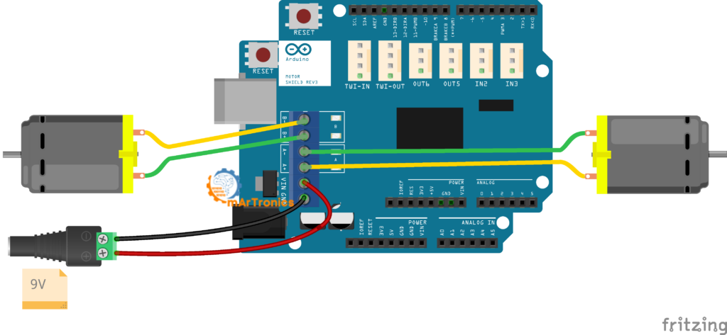
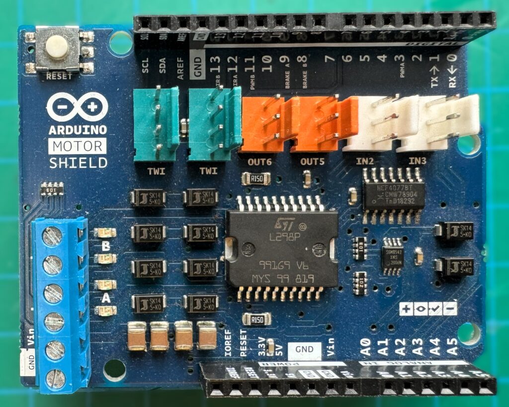
This official shield plugs directly onto the Uno headers, so you do not need jumper wires between the driver and the Arduino. It supports two DC motors (or one stepper motor) at up to 2 A per channel. Direction is controlled with dedicated DIR A and DIR B pins, and speed is set using PWM A and PWM B. While the shield approach is convenient for quick prototyping, it locks you into specific Arduino pins and tends to cost more than a standalone L298N module. It also limits your flexibility in choosing pin assignments.
L293D Motor Shield
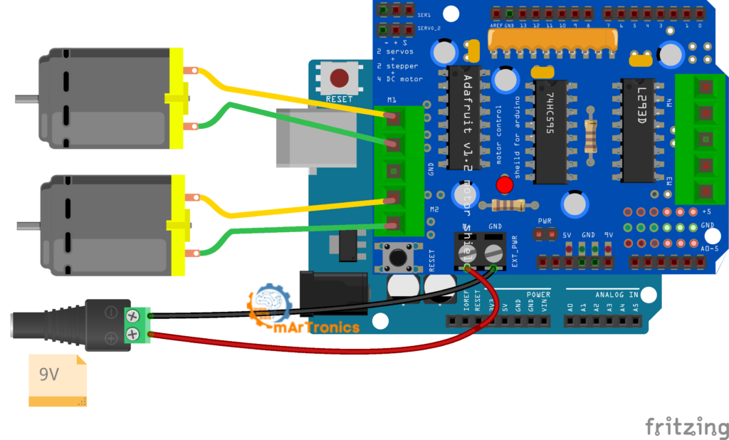
The L293D motor shield (often sold as a clone of the Adafruit Motor Shield V1) uses the L293D chip and can control up to four DC motors or two stepper motors. However, it only provides 0.6 A continuous per channel (1.2 A peak), which is less than the L298N. It is programmed using the Adafruit Motor Shield library (AFMotor.h), which simplifies the code with functions like motor.run(FORWARD) and motor.setSpeed(200). Because of this, the shield is a good choice when you need to control three or four motors from a single Arduino without complex wiring. For example, we use it in our obstacle-avoiding robot car tutorial.
Quick Comparison Table
| Feature | L298N Module | Arduino Motor Shield | L293D Shield |
|---|---|---|---|
| DC motors supported | 2 | 2 | Up to 4 |
| Current per channel | 2 A continuous | 2 A continuous | 0.6 A continuous |
| Motor voltage range | 5 V – 35 V | 5 V – 12 V | 4.5 V – 25 V |
| Form factor | Standalone module with wires | Shield (plugs onto Arduino) | Shield (plugs onto Arduino) |
| PWM speed control | ENA/ENB pins (PWM) | PWM A/B pins | Via AFMotor library |
| Pin flexibility | High (you choose any pins) | Low (fixed pin mapping) | Low (fixed pin mapping) |
| Cost | Very low | Moderate | Low |
| Best for | Custom wiring, robot cars, learning H-bridge fundamentals | Quick prototyping with minimal wiring | Multi-motor projects needing simple code |
For most beginners building their first Arduino robot car or motor control project, the L298N standalone module is the best starting point because it is cheap and handles enough current for most hobby motors. You also learn exactly how direction and speed control work at the hardware level, which prepares you for more advanced projects later.
Frequently Asked Questions (FAQ)
The L298N is a dual H-bridge motor driver used to control the speed and direction of one or two DC motors from a microcontroller like Arduino. For instance, it is commonly found in robot cars, conveyor belt controllers, and automated camera mounts.
Yes, the L298N has two independent channels. In fact, you can use just one channel (Motor A with IN1, IN2, and ENA) and leave the second channel disconnected. The unused channel does not interfere with operation.
Essentially, the L298N motor supply input (+12V terminal) supports 5 V to 35 V. However, the onboard voltage regulator works reliably only up to about 12 V. If your motor supply exceeds 12 V, remove the regulator jumper and provide 5 V logic power separately to the +5V pin.
Typically, DC motors draw a high inrush current at startup, which can cause voltage dips in the power supply. If the Arduino shares the same supply as the motors, this dip can reset the microcontroller. Always use a separate power source for your motors and connect only the GND line between the motor supply and the Arduino.
First, remove the jumper cap from the ENA or ENB pin and connect that pin to a PWM-capable digital pin on the Arduino. Then, use the analogWrite() function with a value between 0 (stopped) and 255 (full speed) to set the motor speed. For more on PWM, see our Arduino servo and PWM control guide.
IN1 and IN2 (and IN3/IN4 for the second motor) control the direction of the motor by determining which way current flows through the H-bridge. ENA and ENB control whether the motor channel is active and at what speed. Think of the IN pins as the steering and the EN pins as the throttle.
An external power supply is required. The L298N needs one connected to its +12V and GND terminals to power the motors. The Arduino 5V pin cannot provide enough current for DC motors. Running motors from the Arduino pin risks damaging the board and causes unreliable operation.
It can. The L298N can drive a single 4-wire stepper motor by using both channels together (IN1–IN4 for the four-step sequence). However, the L298N lacks microstepping capability. For smoother stepper control, a dedicated driver like the A4988 or DRV8825 is usually a better choice.
The L298N can deliver up to 2 A continuous per motor channel, with peak currents up to 3 A for short bursts. If your motors draw more than 2 A under load, you should use a more powerful driver or add active cooling to the heat sink.
A humming motor typically means the PWM duty cycle is too low to overcome the motor’s starting friction. Increase the analogWrite value. Most small DC motors need a minimum PWM value of around 50 to 80 before they start turning. Also check that the motor is not mechanically jammed and that your power supply can deliver enough current.
When the onboard regulator jumper is in place and you supply 7 V–12 V to the +12V terminal, the L298N +5V pin outputs a regulated 5 V that you can connect to the Arduino 5V pin (not Vin). This works but is not recommended for beginners because any motor noise on the supply line can reach the Arduino. For reliable results, keep the Arduino powered through USB or its own dedicated supply.
Absolutely. The L298N is one of the most popular motor drivers for Arduino robot cars. Because of this, its two independent channels are perfect for controlling the left and right motors of a differential-drive robot. In fact, many OmArTronics projects use the L298N or similar drivers, including our Bluetooth-controlled robot car and obstacle-avoiding robot car.
Speed control and pin functions
Typically, DC motors draw a high inrush current at startup, which can cause voltage dips in the power supply. If the Arduino shares the same supply as the motors, this dip can reset the microcontroller. Always use a separate power source for your motors and connect only the GND line between the motor supply and the Arduino.
First, remove the jumper cap from the ENA or ENB pin and connect that pin to a PWM-capable digital pin on the Arduino. Then, use the analogWrite() function with a value between 0 (stopped) and 255 (full speed) to set the motor speed. For more on PWM, see our Arduino servo and PWM control guide.
IN1 and IN2 (and IN3/IN4 for the second motor) control the direction of the motor by determining which way current flows through the H-bridge. ENA and ENB, on the other hand, control whether the motor channel is active and at what speed. Think of the IN pins as the steering and the EN pins as the throttle.
Power supply, limits, and advanced use
Yes, you need an external power supply. The L298N needs one connected to its +12V and GND terminals to power the motors because the Arduino 5V pin cannot provide enough current for DC motors. Running motors from the Arduino pin risks damaging the board and causes unreliable operation.
Yes, the L298N can drive a single 4-wire stepper motor by using both channels together (IN1-IN4 for the four-step sequence). However, the L298N lacks microstepping capability. For smoother stepper control, a dedicated driver like the A4988 or DRV8825 is usually a better choice.
The L298N can deliver up to 2 A continuous per motor channel, with peak currents up to 3 A for short bursts. If your motors draw more than 2 A under load, you should either use a more powerful driver or add active cooling to the heat sink.
Troubleshooting and advanced topics
A humming motor typically means the PWM duty cycle is too low to overcome the motor’s starting friction, so increase the analogWrite value. Most small DC motors need a minimum PWM value of around 50 to 80 before they start turning. Also check that the motor is not mechanically jammed and that your power supply can deliver enough current.
When the onboard regulator jumper is in place and you supply 7 V to 12 V to the +12V terminal, the L298N +5V pin outputs a regulated 5 V that you can connect to the Arduino 5V pin (not Vin). This works, but I would not recommend it for beginners because motor noise on the supply line can reach the Arduino. For more reliable results, keep the Arduino powered through USB or its own dedicated supply.
Yes. The L298N is one of the most popular motor drivers for Arduino robot cars. Its two independent channels work well for controlling the left and right motors of a differential-drive robot. In fact, many OmArTronics projects use the L298N or similar drivers, including our Bluetooth-controlled robot car and obstacle-avoiding robot car.
Resources and Next Projects
If you want to keep building on what you learned here, these related OmArTronics tutorials and projects are good next steps.
- Build an obstacle-avoiding robot car — combine your motor control skills with an ultrasonic sensor to create a robot that navigates around objects autonomously.
- Build a Bluetooth-controlled robot car — add an HC-05 Bluetooth module and control your robot from your smartphone.
- Arduino HC-05/HC-06 Bluetooth module tutorial — learn how to set up wireless communication between your phone and Arduino.
- Learn distance measurement with the Arduino ultrasonic distance sensor (HC-SR04) tutorial — a key skill for mobile robots.
- Arduino servo motor control guide — expand into servo motors for robotic arms, pan-tilt mechanisms, and more.
- Revisit the Arduino programming basics if you need a refresher on the Arduino IDE, sketch structure, or core functions.
- Build an Arduino radar with ultrasonic sensor and servo — a fun project that combines servo control with distance sensing.
Conclusion
That covers everything you need to get DC motors running with the L298N and Arduino. You now know how the dual H-bridge works, how to wire it up, and how to control motor speed and direction using PWM and basic digital logic. You also understand the L298N pinout, why a separate motor power supply matters, how the common ground ties everything together, and how to fix the most common problems beginners run into.
The L298N is a solid and affordable starting point for Arduino DC motor control, so if you want to put these skills to work, try one of the robot car builds linked above.
3 thoughts on “L298N Motor Driver with Arduino: DC Motor Control Guide”