

📋 Quick Summary
A complete beginner guide to 3D printing covering FDM technology, filament materials (PLA, PETG, ABS, TPU), the full CAD-to-print workflow with Autodesk Inventor and Ultimaker Cura, printer setup, slicer settings, and practical tips for successful first prints. Ideal starting point before 3D printing robot parts.
3D printing turns digital designs into real, physical objects, one layer at a time. Whether you want to prototype a robot chassis, print a custom sensor mount, or just understand how additive manufacturing works, this guide covers the 3D printing basics you need to get started. You will learn how FDM 3D printing works, which materials to choose, how to design parts in Autodesk Inventor, how to prepare them in Cura slicer, and how to avoid common beginner mistakes.
This article is written for makers, students, and engineers who want a practical introduction to 3D printing, from the first CAD sketch to a finished printed part.
What you will learn
- What 3D printing is and how FDM technology works step by step
- How different 3D printing technologies (FDM, SLA, SLS) compare
- Which 3D printing materials are best for beginners and why
- The complete 3D printing workflow from CAD design to finished print
- How to use Autodesk Inventor for 3D design with printing in mind
- How to use Cura slicer to prepare your model for the printer
- Key design rules for printable parts
- How to set up your printer and troubleshoot common problems
- Practical project ideas to build next
What is 3D printing?
3D printing, also known as additive manufacturing, is the process of building a three-dimensional object from a digital file by depositing material layer by layer. Unlike traditional subtractive manufacturing, which removes material from a solid block, 3D printing adds material only where needed. This reduces waste and makes it possible to produce complex shapes that would be difficult or impossible to machine from a block.
The technology goes back to the 1980s, when Charles Hull developed stereolithography (SLA) as the first commercial rapid prototyping method. Then, in 1989, S. Scott Crump patented Fused Deposition Modelling (FDM), which has since become the most common 3D printing technology for hobbyists, educators, and small manufacturers. Today, FDM printers are affordable and widely available, and you will find them in fields ranging from aerospace to robotics to education.
How the 3D printing workflow works
Every 3D print follows the same basic workflow, regardless of the printer or material you use. Understanding this process also helps you troubleshoot problems at each stage.
From design to slicing
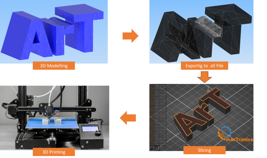
Step 1 – Create or obtain a 3D model. Use CAD software such as Autodesk Inventor, Fusion 360, or Tinkercad to design your part. Alternatively, download ready-made models from repositories like Thingiverse or Printables.
Next, export to STL. Save your CAD model in STL (stereolithography) format. STL files describe the outer surface of your 3D model as a mesh of triangles. When exporting, choose a resolution that balances file size and surface quality.
Step 3 – Open in a slicer. Import the STL file into slicing software like UltiMaker Cura. The slicer then divides your model into horizontal layers and calculates the exact toolpath the printer nozzle will follow.
Then, configure your print settings. Choose layer height, infill density, print speed, support structures, and temperature settings based on your material and the requirements of your part.
From G-code to finished part
Step 5 – Generate G-code. The slicer outputs a G-code file, which is a set of machine-readable instructions that tell the printer how to move, how much filament to extrude, and at what temperature to operate.
Now, start the print. Transfer the G-code to your printer (via USB, SD card, or network) and start the print. Monitor the first few layers carefully to ensure proper adhesion.
Finally, post-process your part. Remove the print from the bed, clean up support structures, and optionally sand, paint, or assemble your part with other components.
3D printing technologies compared: FDM, SLA, and SLS
There are several additive manufacturing methods, each suited to different applications. The three most common technologies are FDM, SLA/DLP, and SLS. The table below provides a practical comparison to help you understand where each fits.
| Feature | FDM (Fused Deposition Modelling) | SLA / DLP (Resin-Based) | SLS (Selective Laser Sintering) |
|---|---|---|---|
| How it works | Melts and extrudes thermoplastic filament layer by layer | Cures liquid resin with a UV laser or projected light | Fuses powdered material with a laser |
| Typical materials | PLA, ABS, PETG, TPU | Photopolymer resins (standard, tough, flexible) | Nylon, glass-filled nylon, TPU powder |
| Surface finish | Visible layer lines; moderate detail | Very smooth; high detail | Slightly grainy; good detail |
| Supports needed | Yes, breakaway or soluble | Yes, resin supports | No (powder acts as support) |
| Best for | Prototyping, functional parts, hobbyist projects | Detailed models, jewelry, dental applications | Strong functional parts, batch production |
| Cost | Low (printers from ~$200) | Medium (printers from ~$300) | High (industrial machines) |
| Beginner-friendly | Yes — most common entry point | Moderate — requires resin handling and curing | No — typically industrial |
For hobbyists, makers, and students, FDM is the clear starting point because it is affordable, uses safe and widely available materials, and produces functional parts suitable for robotics, enclosures, brackets, and mechanical prototypes.
FDM 3D printing explained
Fused Deposition Modelling (FDM) is the most widely used 3D printing technology for desktop printers. Because of this, understanding how it works helps you make better design choices and troubleshoot common printing problems.
How FDM works step by step
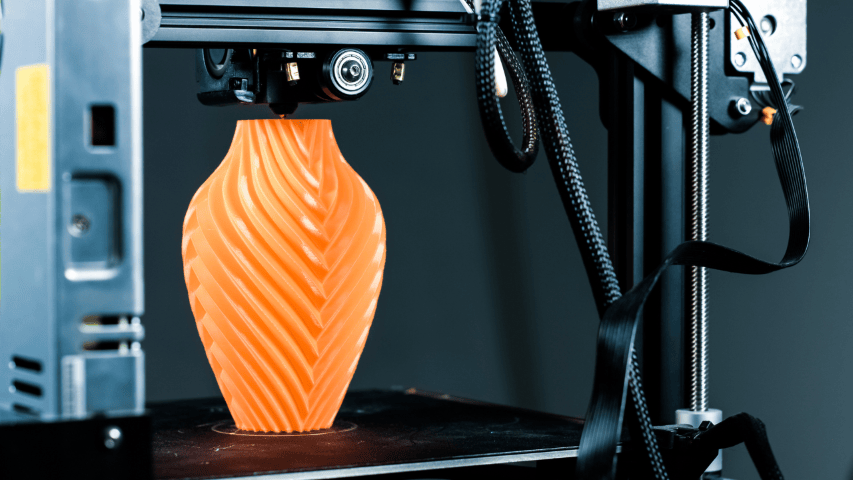
An FDM printer works by feeding a spool of thermoplastic filament (typically 1.75 mm in diameter) into a heated extruder assembly. Inside the extruder, a motor-driven gear grips the filament and pushes it through a hot end, where it melts at temperatures between roughly 190 °C and 260 °C depending on the material. The molten plastic is then forced through a nozzle (commonly 0.4 mm diameter) and deposited onto a build plate in a precise pattern.
The print head then moves along the X and Y axes to trace each layer, while the build plate (or the print head itself, depending on the printer design) moves along the Z axis to create successive layers. Each layer bonds to the one below it as the plastic cools and solidifies. This layer-by-layer deposition continues until the entire object is built.
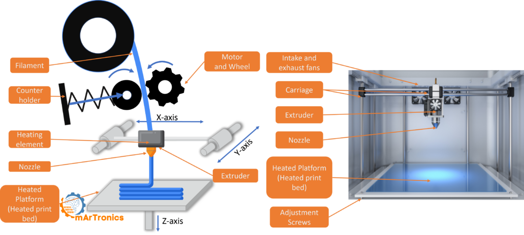
Key components of an FDM printer
Extruder and hot end – The extruder feeds filament into the hot end, which melts it and pushes it through the nozzle. Direct-drive extruders mount directly above the hot end, while Bowden setups use a tube to guide filament from a remote extruder.
Nozzle – The nozzle determines the minimum feature width. Standard nozzles are 0.4 mm. Smaller nozzles produce finer detail but print more slowly.
Heated build plate (bed) – The heated bed helps the first layer stick and prevents warping, especially with materials like ABS and PETG. Bed surfaces may include glass, PEI sheets, or magnetic flex plates.
Frame and motion system – Stepper motors drive belts and lead screws to move the print head and bed along the X, Y, and Z axes with high precision.
Cooling fan – A part-cooling fan directs air onto freshly deposited layers to solidify them quickly. This improves overhang performance and surface quality.
FDM printers are popular among hobbyists because they are affordable, relatively easy to maintain, and also work with a wide range of thermoplastic materials. Many of the robotic arm projects and line-following robot builds featured on OmArTronics use FDM-printed structural parts.
3D printing materials: what beginners need to know
Choosing the right filament is one of the first decisions a beginner faces. The material affects strength, flexibility, surface finish, and how easy the print is to get right, so choosing wisely matters. The table below covers the most common 3D printing materials and their practical characteristics.
Materials comparison table
| Material | Full Name | Properties | Nozzle Temp | Bed Temp | Best For | Beginner Notes |
|---|---|---|---|---|---|---|
| PLA | Polylactic Acid | Biodegradable, easy to print, low warping, low odor | 190–220 °C | 20–60 °C (or no heated bed) | Prototypes, decorative parts, enclosures, brackets | Best first material. Forgiving, widely available, minimal setup required |
| ABS | Acrylonitrile Butadiene Styrene | Strong, heat-resistant, durable, prone to warping | 220–250 °C | 90–110 °C | Functional parts, mechanical components, housings | Requires heated bed and enclosed chamber; use good ventilation due to fumes |
| PETG | Polyethylene Terephthalate Glycol | Strong, flexible, chemical-resistant, low warping | 220–250 °C | 70–90 °C | Functional parts, outdoor use, food-safe containers | Good second material. Easier than ABS but stronger than PLA |
| PVA | Polyvinyl Alcohol | Water-soluble, used as support material | 185–200 °C | 45–60 °C | Dissolvable supports for complex geometries | Requires dual-extruder printer; used with PLA |
| HIPS | High Impact Polystyrene | Lightweight, soluble in d-Limonene | 220–235 °C | 90–110 °C | Dissolvable supports for ABS prints | Requires enclosed chamber; used with ABS |
Which filament should you start with?
Start with PLA. It prints at lower temperatures, sticks well to most bed surfaces, and produces reliable results without needing an enclosed chamber or special ventilation. Once you are comfortable with PLA, try PETG for stronger functional parts, and consider ABS only when you need heat resistance and have proper ventilation.

Setting up a 3D printer for your first print
Proper printer setup makes the difference between a clean first print and hours of frustration. Before sending your first G-code file, follow these steps to prepare your FDM printer.
Bed leveling
A level bed ensures the first layer is deposited at a uniform distance from the nozzle across the entire build surface. Most printers include a manual leveling procedure using a piece of paper as a feeler gauge. Slide the paper between the nozzle and the bed at each corner and adjust the leveling knobs until you feel slight friction. Even printers with automatic bed leveling (ABL) benefit from periodic manual checks.
Temperature settings
Set the nozzle temperature and bed temperature according to the filament manufacturer’s recommendations. For PLA, start with a nozzle temperature around 200 °C and a bed temperature around 50–60 °C. You should also print a temperature tower test to find the optimal nozzle temperature for each specific filament brand you use.
First layer checks
The first layer is the most important part of any print, so watch it closely. The filament should be slightly squished onto the bed. Not too flat (which causes elephant’s foot) and not too round (which means the nozzle is too far from the bed). A good first layer looks smooth, has no gaps between lines, and sticks firmly to the build surface.
Ventilation and safety
Even PLA emits ultrafine particles during printing, so print in a well-ventilated room or near an open window. If you print ABS, an enclosed printer with an air filtration system or active carbon filter is strongly recommended. Never leave a 3D printer running unattended for extended periods, especially during your first prints, and keep a fire extinguisher accessible in your workspace.
Calibration mindset
3D printing is an iterative process, so expect to calibrate your printer over several test prints. Print calibration cubes, temperature towers, and retraction tests to dial in your settings. Even a new filament roll of the same brand and type may need minor adjustments. Good calibration habits save time and material in every future print.
Practical tips for better 3D prints
Once your printer is set up, these practical tips address the most common challenges beginners face and help you produce consistent, quality prints.
First layer adhesion
Poor bed adhesion is the number one cause of failed prints. To prevent it, clean your bed surface with isopropyl alcohol before each print. A glue stick, painter’s tape, or a PEI sheet can also help with grip. If your first layer still lifts despite all this, increase the bed temperature by 5 °C increments or slow down the first layer speed to 15–20 mm/s.
Print orientation
Orientation on the build plate affects strength, surface quality, and support usage. Where possible, lay parts flat to minimize overhangs. For mechanical parts, orient the strongest direction of the part along the X/Y plane, since layer adhesion (Z direction) is always the weakest axis in FDM printing.
Supports
Supports are sacrificial structures generated by the slicer to hold up overhanging geometry. They use extra material, however, and leave marks on the surface when removed. Where possible, minimize supports by designing parts with self-supporting angles (under 45° from vertical) or by choosing smart print orientations.
Infill
Infill is the internal structure of your print. 100% infill means solid, which is rarely necessary. For most prototypes, 15–20% infill provides enough strength while also saving material and time. For structural or mechanical parts like robotic arm joints, increase infill to 40–60% and consider using a stronger infill pattern like cubic or gyroid.
Layer height
Layer height controls the resolution and speed of your print. A 0.2 mm layer height is a solid default for functional parts. Use 0.12 mm for finer detail or visible surfaces, and 0.28 mm for rough prototypes where speed matters more than aesthetics. As a rule, layer height should not exceed roughly 75% of your nozzle diameter.
Stringing and retraction
Stringing occurs when thin threads of filament appear between separate parts of a print, usually because the nozzle oozes during travel moves. To reduce stringing, enable retraction in your slicer (pulling filament back slightly during travel), increase travel speed, and lower the nozzle temperature slightly.
Warping
Warping happens when corners of a print lift from the bed due to uneven cooling and material shrinkage. It is most common with ABS, but it can also occur with PETG. To fix it, make sure bed temperature is correct, use an enclosed printer if possible, add a brim in your slicer settings, and avoid placing parts in drafty areas.
When to slow down
Printing too fast can cause layer adhesion issues, ringing (surface ripples), and poor overhang performance. If you notice quality problems, reduce print speed by 10–20%. For small or detailed parts, slower speeds allow each layer to cool properly before the next one is deposited.
3D design with Autodesk Inventor for 3D printing
Autodesk Inventor is a professional parametric 3D CAD application used in mechanical engineering, product design, and manufacturing. For makers who want to go beyond simple shapes and build precise, functional 3D-printed parts, Inventor is a strong choice because it fits cleanly into the 3D printing workflow.
Why Inventor is useful for engineering-oriented 3D design
Autodesk Inventor is built around parametric modelling, meaning every feature of your design is defined by dimensions and constraints that can be changed at any time. For example, if you design a motor mount with a 28 mm bore and later need to adjust it to 30 mm, you change one parameter and the entire model updates automatically. This beats redrawing parts manually and is especially useful for iterative prototyping, which is a big part of 3D printing workflows.
Inventor also supports assemblies, so you can combine multiple parts into a single project and check for interferences before printing. For robot builds like the 6-DOF robotic arm with Bluetooth control or the OmObiArm mobile robot, this assembly workflow helps you verify that printed joints, brackets, and chassis parts fit together correctly before committing to a print.
Designing parts with manufacturing in mind
When designing for FDM printing in Inventor, keep these practical rules in mind. Avoid very thin walls (below 1.2 mm for a 0.4 mm nozzle). Add fillets to sharp internal corners to reduce stress concentrations. Use chamfers instead of small overhangs where possible. Design mounting holes slightly oversized (by 0.2–0.3 mm) to account for the dimensional inaccuracy in FDM printing. Also think about how the part will sit on the print bed while you design. The flat face with the largest surface area usually makes the best base.
Exporting STL from Inventor
To prepare your Inventor model for slicing, first export it as an STL file. In Inventor, go to File → Export → CAD Format, then select STL. In the export options, set the resolution to “High” for detailed parts or “Medium” for larger structural components. Excessively high resolution creates unnecessarily large files without visible improvement in print quality. After exporting, open the STL in your slicer to verify the mesh is clean, with no holes, inverted normals, or non-manifold edges.
Avoiding overcomplicated geometry
Inventor can model extremely complex surfaces and features, but not everything that looks good in CAD prints well on an FDM machine. Avoid very thin protrusions, unsupported horizontal bridges longer than 10–15 mm, and tiny features below 0.8 mm that the nozzle cannot resolve. Instead, simplify geometry where the mechanical function allows it. Simpler models slice faster and print more reliably.
Cura slicer basics: preparing your model for printing
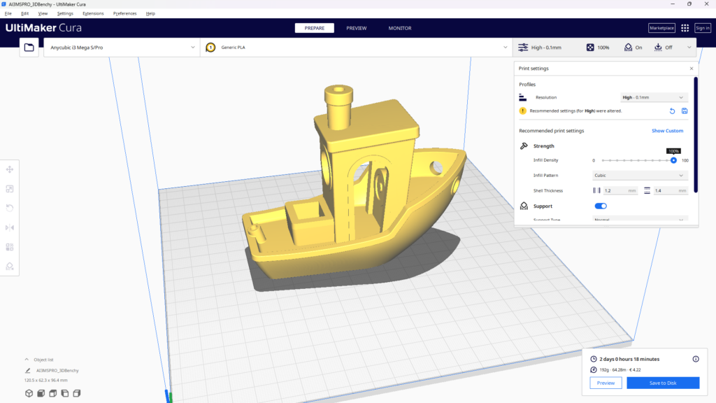
UltiMaker Cura is one of the most popular slicing applications in the 3D printing community. It is free, open source, and also compatible with hundreds of FDM printers. Cura translates your 3D model into the G-code instructions your printer needs to build the object layer by layer.
What a slicer does
A slicer takes your STL file and cuts it into horizontal layers at the layer height you specify. Then, for each layer, it calculates the toolpath, which is the exact route the nozzle will follow to deposit filament. It also adds structural elements you do not see in the original model, including walls (outer shells), infill patterns, support structures, skirts, brims, and rafts.
Key Cura settings explained
Layer height – The thickness of each printed layer. Lower values (0.12 mm) produce smoother surfaces, while higher values (0.28 mm) print faster. A 0.2 mm layer height is a good starting point for most prints.
Infill density and pattern – Controls how solid the inside of your print is. 20% infill is typical for prototypes. Choose grid for simple parts, or cubic/gyroid for parts that need strength in all directions.
Wall count (shell thickness) – The number of perimeter lines on each layer. Two or three walls usually provide a good balance between strength and print time. However, increase walls for parts that need to resist impact or mechanical stress.
Support structures – Enable supports for overhangs steeper than 45°. Cura offers “normal” supports (touching build plate only) and “everywhere” supports. Tree supports are also worth trying for organic shapes because they are easier to remove and leave fewer marks.
Print speed – Speeds of 50–60 mm/s work well for PLA by default. Reduce speed for complex geometry or small features. For large, simple parts, you can increase speed once you have verified quality at standard speeds.
Adhesion type – Skirt (a line around the print to prime the nozzle), brim (extra lines attached to the print base for better adhesion), or raft (a full platform under the print). Use a brim for tall or narrow parts that tend to tip or warp.
Using Cura’s preview mode
After slicing, always check Cura’s preview mode before sending G-code to the printer. The preview shows the exact toolpath layer by layer, color coded by feature type (walls, infill, supports, travel moves). This lets you verify that supports are placed correctly, infill density looks right, and no unexpected gaps or artifacts exist in the sliced model. Fixing problems in the slicer takes seconds, while fixing them on a failed print wastes hours and material.
Design rules for 3D printing
Designing for 3D printing (often called DfAM, or Design for Additive Manufacturing) requires thinking about how the printer will build your part. These rules apply whether you use Inventor, Fusion 360, or any other CAD tool.
Geometry and wall dimensions
Overhang awareness – FDM printers can handle overhangs up to about 45° from vertical without supports. Beyond that angle, you need support structures or a design change. Where possible, redesign features to stay within the self-supporting range.
Wall thickness – Minimum wall thickness should be at least two to three times your nozzle diameter. For a 0.4 mm nozzle, keep walls at 0.8 mm minimum, and preferably 1.2 mm or more for structural parts.
Tolerances for assemblies – FDM parts are not dimensionally perfect. For press-fit joints, add 0.1–0.2 mm clearance. For sliding or rotating joints, add 0.3–0.5 mm. Always test print a small tolerance gauge before committing to a large multi-part assembly.
Orientation and assembly planning
Print orientation planning – Orient your part so that critical surfaces face upward (away from the bed) for the best finish. Put structural load paths along the X/Y plane, where layer bonds are strongest. Also avoid situations where thin features must be printed vertically, because they tend to break along layer lines.
Support minimization – Every support you print must be removed later, costing time and potentially damaging surfaces. Design parts to be self supporting where possible: use chamfers instead of horizontal overhangs, split complex parts into printable sub-assemblies, and use teardrop shaped holes instead of circular ones for horizontal bores.
Assembly-fit thinking – When designing multi-part assemblies (such as a robotic arm or a custom enclosure), think about how parts will be joined. Design snap-fit features, screw bosses, or alignment pins directly into your CAD model. This saves post-processing time and creates a more reliable final assembly.
Examples of 3D printing in maker projects
3D printing is most useful when applied to real projects. Below are some practical applications for makers and robotics enthusiasts.
Robot chassis and structural frames – Custom designed and 3D-printed chassis parts let you build robots tailored to specific sensor configurations and motor sizes. The KY-033 line-following robot and the TCS34725 line-following robot both use 3D-printed frames designed in CAD software.
Robotic arm joints and brackets – The 6-DOF robotic arm project uses 3D-printed links, joint housings, and servo mounts that would be expensive or impossible to produce with traditional methods at hobbyist scale.
Sensor mounts and custom enclosures – 3D printing lets you create perfectly fitting mounts for ultrasonic sensors, cameras, or Arduino boards. Instead of using generic off the shelf brackets, you can design mounts that match your exact project dimensions and screw patterns.
Gears, pulleys, and mechanical components – FDM can produce functional gears, timing pulleys, and linkages for low load applications. Inventor’s parametric tools make it easy to design these components with precise tooth profiles and bore dimensions.
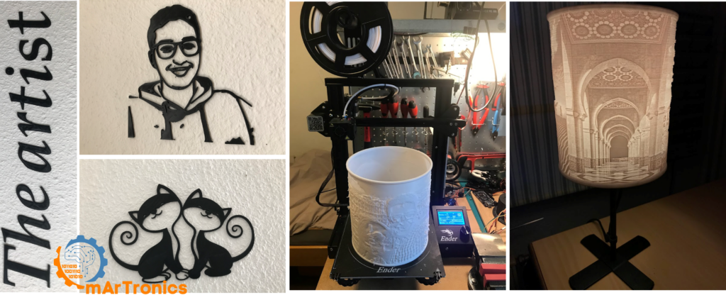
Decorative and functional household items – Beyond engineering, 3D printing also works for personalized items like wall art, lampshades, organizers, and phone stands.
Troubleshooting common 3D printing problems
Even experienced users encounter printing failures, so knowing how to diagnose and fix common issues quickly is part of learning 3D printing basics. Here are the most frequent problems and their solutions.
Adhesion and surface issues
Poor bed adhesion – The print detaches from the bed during printing. To fix this, clean the bed surface, re-level the bed, increase bed temperature, slow down the first layer, or add a brim in the slicer.
Stringing – Thin threads appear between parts of the print. Increase retraction distance and speed, lower nozzle temperature slightly, and increase travel speed in the slicer.
Warping – Corners of the print curl upward from the bed. To fix this, use an enclosed printer, increase bed temperature, add a brim, and avoid placing the printer in drafty locations.
Extrusion and software problems
Under-extrusion – The print shows gaps, thin walls, or missing layers. Check for a partially clogged nozzle, verify the filament diameter setting in the slicer, increase the flow rate slightly, or check whether the extruder gear is gripping the filament properly.
Clogged nozzle – Filament stops extruding or extrudes inconsistently. First, perform a cold pull (heat the nozzle, push filament in, let it cool, then pull it out to extract debris). If that does not work, use a nozzle cleaning needle or replace the nozzle.
Rough or blobby surfaces – Usually caused by over-extrusion, excessive temperature, or inconsistent filament diameter. To fix it, reduce flow rate, lower nozzle temperature, and make sure your filament is stored in a dry environment.
Failed supports – Supports collapse or do not detach cleanly. In Cura, try tree supports instead of normal supports. Increase the support interface density for better print surfaces, or adjust the support Z distance for easier removal.
Bad STL export – The slicer shows holes or errors in the model. Re-export from your CAD software at a higher mesh resolution. In Inventor, verify the STL export settings and check the model for open surfaces or non-manifold edges before exporting. You can also repair STL files using free tools like Meshmixer or the built-in repair function in Windows 3D Builder.
Frequently asked questions (FAQ)
For beginners, an FDM printer in the $200–$400 range typically offers the best balance of quality, reliability, and learning potential. Popular options include the Creality Ender 3 series, Prusa Mini, and Bambu Lab A1 Mini. Look for features like automatic bed leveling, a heated bed, and good community support.
Start with PLA filament. It is the easiest material to print, requires low temperatures, produces minimal odor, and works on virtually every FDM printer. Once you are comfortable with PLA, PETG is a strong next step for more durable parts.
Print time depends on the size of the object, layer height, infill density, and print speed. For example, a small calibration cube may take 20–30 minutes. A medium-sized part like a phone stand might take 2–4 hours. Large structural components for a robot chassis can take 8–20 hours or more. Your slicer will estimate the time before you start printing.
FDM melts and extrudes thermoplastic filament layer by layer. In contrast, SLA uses a UV laser to cure liquid resin. FDM is cheaper and better for functional parts; SLA produces finer detail and smoother surfaces but requires resin handling and post-curing. Most beginners start with FDM.
Not right away. You can start by downloading ready-made STL files from repositories like Thingiverse or Printables. But to create custom parts, especially for robotics and engineering projects, you will eventually want to learn CAD software like Autodesk Inventor, Fusion 360, or Tinkercad.
More 3D printing questions
A slicer converts a 3D model (STL file) into G-code, which is the set of machine-readable instructions that tell the printer how to move, how much filament to extrude, and at what temperature to operate. UltiMaker Cura and PrusaSlicer are two popular free slicers.
Try a cold pull first: heat the nozzle, push filament in manually, let it cool to around 90 °C, then pull the filament out firmly. This extracts debris from inside the nozzle. If the clog persists, use a cleaning needle or replace the nozzle entirely. Nozzles are inexpensive consumables.
Yes, and this is one of the most practical uses of desktop 3D printing. You can print custom enclosures for Arduino boards, sensor mounts, robot chassis, servo brackets, gear trains, and cable management clips. Many projects on OmArTronics, including the 6-DOF robotic arm and Bluetooth-controlled robot car, rely entirely on 3D-printed structural parts.
G-code is the standard language used to control CNC machines, including 3D printers. Each line of G-code is a command that moves the print head to a specific position, sets the nozzle temperature, or extrudes a specific amount of filament. Your slicer generates G-code automatically from your 3D model.
Entry-level FDM printers cost $200–$400, and a 1 kg spool of PLA filament costs roughly $15–$25. Most small parts use only a few grams of material, making individual prints very affordable. The main cost is the printer itself and the time investment in learning calibration and design.
Resources and next steps
Now that you have the basics down, here are practical next steps to keep building your 3D printing skills and start applying them to real projects.
Recommended beginner software
Autodesk Inventor – Professional parametric CAD for engineering parts and assemblies. Free for students and educators through the Autodesk Education plan.
Autodesk Fusion 360 – A cloud-based CAD/CAM tool with a free personal use license. A good alternative if you want integrated simulation and manufacturing tools.
Tinkercad – A free browser-based 3D modelling tool ideal for absolute beginners and simple shapes. Great for learning basic concepts before moving to Inventor or Fusion.
UltiMaker Cura – Free, open source slicing software compatible with most FDM printers. The best starting slicer for beginners.
PrusaSlicer – Another free, open source slicer with advanced features for experienced users. Worth trying once you are familiar with Cura.
Suggested OmArTronics tutorials to explore next
Apply your new 3D printing and design skills to hands-on robotics projects. These OmArTronics tutorials use 3D-printed parts extensively and will help you put theory into practice.
- DIY 6-DOF Robotic Arm – 3D Print, Wire, and Program Step by Step – Design and print all structural parts for a fully functional six-axis robotic arm controlled by Arduino and PCA9685 servo drivers.
- DIY 6-DOF Robotic Arm with Bluetooth Control – Extend the robotic arm project with wireless Bluetooth control using HC-05 and a custom Android app built in MIT App Inventor.
- Building a Line Following Robot with KY-033 Sensors – A beginner-friendly project that combines 3D-printed chassis design with Arduino sensor programming.
- OmObiArm: Mobile Robot with Integrated Robotic Arm – An advanced build that uses 3D-printed parts for both the mobile platform and the mounted robotic arm.
- Arduino Servo Control Guide: SG90, PWM, and PCA9685 – Learn servo control fundamentals that pair naturally with 3D-printed mechanical assemblies.
First projects to print
If you are setting up your printer for the first time, then start with these practical beginner prints to build confidence and calibrate your machine.
- Calibration cube (20 mm XYZ) – Verify dimensional accuracy and identify extrusion or leveling problems.
- Temperature tower – Find the optimal nozzle temperature for your filament.
- Benchy (3D Benchy tugboat) – The standard benchmark print that tests overhangs, bridging, small details, and stringing in one compact model.
- Simple phone stand or cable organizer – A practical first functional print that you will actually use.
- Arduino Uno case – Design a custom enclosure for your Arduino board as your first CAD-to-print exercise.
Conclusion
3D printing lets you turn a digital design into a physical object on your own workbench. This guide covered the 3D printing basics, including how FDM works, which materials to pick, how to design parts in Autodesk Inventor, how to slice them in Cura, and how to set up your printer and fix common issues.
The best way to learn 3D printing is to start printing. Begin with PLA, print calibration tests, then design your first simple part in CAD and gradually take on more complex projects. Every failed print teaches you something about the process.
When you are ready to apply your skills to real builds, explore the robotic arm project or the line-following robot tutorials on OmArTronics. These projects combine 3D-printed parts with Arduino electronics and real engineering challenges, which is exactly where 3D printing skills pay off.
3 thoughts on “Introduction to 3D Printing: Workflow, Materials, Inventor, Cura, and Beginner Tips”