
📋 Quick Summary
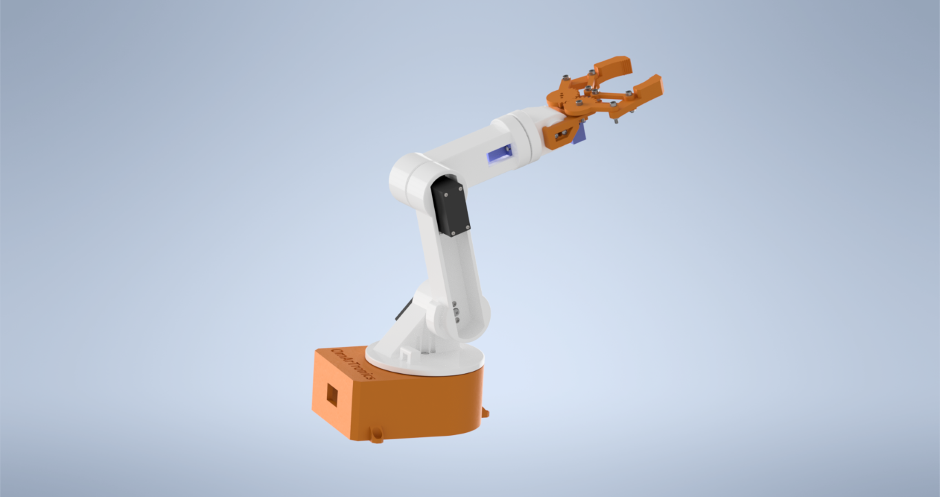
Build a complete DIY 6-DOF robotic arm from scratch using 3D-printed parts, MG996R and SG90 servo motors, an Arduino Uno, and a PCA9685 servo driver. This step-by-step guide covers the full workflow from CAD design in Autodesk Inventor through 3D printing, mechanical assembly, electronics wiring, and Arduino programming with potentiometer-based manual control.
This tutorial walks you through building a DIY 6-DOF robotic arm from scratch. You will design each part in Autodesk Inventor, 3D print them, wire up the electronics with an Arduino, and program real-time servo control using potentiometers.
The arm uses three MG996R high-torque servos for the base, shoulder, and elbow joints, and three SG90 micro servos for the wrist and gripper. If you want a primer on how these motors work, see our servo motor control guide. Each servo is controlled in real time by its own 10 kΩ potentiometer, and all six PWM signals run through a PCA9685 servo driver board over I²C. That keeps the wiring tidy and frees up Arduino pins for future add-ons.
Whether you are a hobbyist building your first robot or an engineering student looking for a hands-on mechatronics project, this guide walks you through every detail with a full bill of materials, print settings, wiring diagrams, and source code. Once you are ready, you can watch the full build video below or continue reading the written tutorial.

Project overview
The build has four phases: CAD design, 3D printing, mechanical assembly, and electronics wiring with programming. Every 3D-printable STL file is modeled in Autodesk Inventor with precise tolerances for the servo mounts and bearing seats, so parts fit together without extra work.
On the electronics side, an Arduino Uno reads analog values from six 10 kΩ potentiometers and sends I²C commands to a PCA9685 16-channel PWM driver, which outputs the correct pulse widths to each servo. This setup keeps high servo current completely separate from the Arduino and leaves room to add sensors or wireless modules later.
Complete bill of materials
Before you start, gather every component listed in the table below. Having everything on hand will save you from frustrating mid-build pauses.
6-DOF robotic arm parts and components
| Item | Quantity | Part | Description |
|---|---|---|---|
| 1 | 1 | Base_1 | Base platform |
| 2 | 1 | base_link_upper1 | Upper base section |
| 3 | 1 | arm_link_1 | First arm link |
| 4 | 1 | arm_link_2 | Second arm link |
| 5 | 1 | arm_link_3 | Third arm link |
| 6 | 1 | gripper_base | Gripper base |
| 7 | 1 | Gripper_2 | Gripper finger |
| 8 | 1 | Gear_right | Gripper gear (right) |
| 9 | 1 | Gear_left | Gripper gear (left) |
| 10 | 1 | Gripper | Gripper assembly |
| 11 | 4 | Link | Gripper link parts |
| 12 | 2 | Spacer | Gripper joint spacers |
| 13 | 3 | MG996R Servo Motor | High-torque servo (base, shoulder, elbow) |
| 14 | 3 | SG90 Micro Servo Motor | Micro servo (wrist, gripper) |
| 15 | 14 | ANSI B18.6.4 No.2-32 3/8″ | Truss head screw, No.2-32 |
| 16 | 2 | ANSI B18.6.4 No.2-32 1/4″ | Truss head screw, No.2-32 |
| 17 | 3 | DIN 7985 M1.6×2-Z | M1.6×2 cross-recess screw |
| 18 | 7 | ISO 4762 M3x16 (AS 1420) | M3×16 hex socket screw |
| 19 | 12 | ISO 4032 M3 (AS 1112) | M3 hex nut |
| 20 | 2 | ANSI B18.6.4 No.2-32 1/2″ | Truss head screw, No.2-32 |
| 21 | 3 | MG955 Horn | Horn for MG996R |
| 22 | 3 | DIN 7985 M3x6-Z | M3×6 cross-recess screw |
| 23 | 3 | SG90 Servo Horn | Horn for SG90 |
| 24 | 2 | ANSI B18.6.4 No.2-32 3/8″ | Truss head screw, No.2-32 |
| 25 | 12 | ANSI B18.6.4 No.3-28 1/2″ | Truss head screw, No.3-28 |
| 26 | 1 | Ball Bearing 6806ZZ (30x42x7) | Deep-groove bearing (30×42×7) |
| 27 | 1 | Arduino Uno or Mega | Main controller |
| 28 | 1 | PCA9685 Servo Driver Board | 16-ch PWM driver (I²C) |
| 29 | 6 | 10kΩ Potentiometer | Analog control knob, one per servo |
| 30 | 1 | Breadboard | Wiring base for potentiometers |
| 31 | 1 | 5V 10A Power Supply | Servo power source |
| 32 | 1 | Jumper Wires (male-male) | Arduino to PCA9685 connections |
| 33 | 1 | Jumper Wires (male-female) | Potentiometer to Arduino connections |
| 34 | 1 | Wooden Board | Arm mounting platform |
Designing the parts in Autodesk Inventor
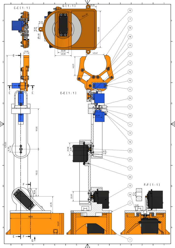
The first phase is modeling every component in Autodesk Inventor. This parametric CAD software lets you define exact dimensions, fillet edges for strength, and verify fit before a single gram of filament gets extruded. If you are new to Inventor or 3D printing, check out our Introduction to 3D Printing and 3D Design with Inventor before starting.
Two servo types drive the design constraints. The SG90 micro servos handle the lighter upper joints and gripper because of their compact size, while the MG996R servos power the base rotation and the two heavy-lift shoulder and elbow joints, providing the torque needed to move the full arm. The technical drawing below shows all part dimensions, sectional views, and assembly relationships. Use it as your reference when checking print accuracy.
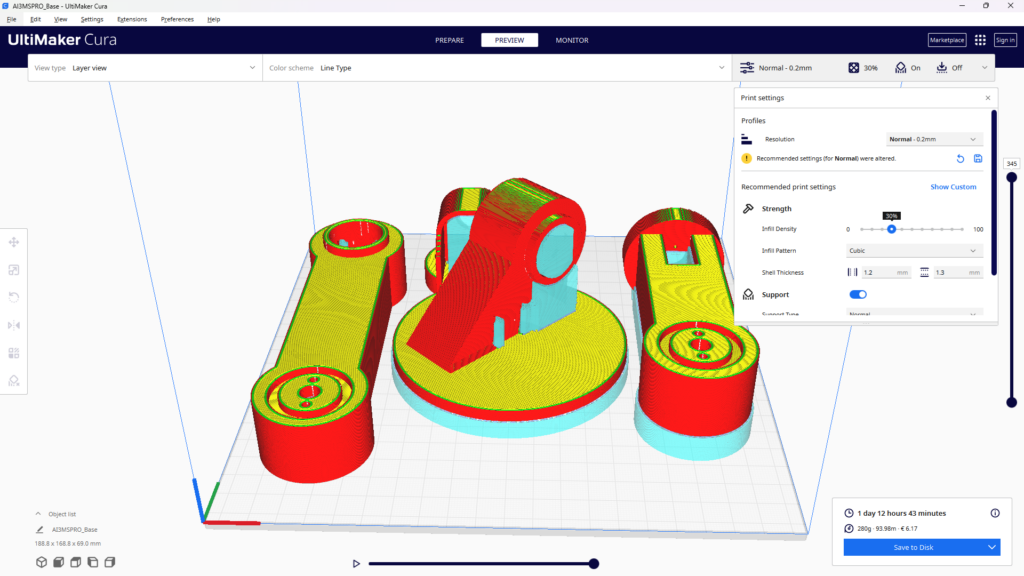
3D printing the 6-DOF robotic arm components
Once your STL files are exported from Inventor, fire up the 3D printer. For this project, PLA filament works well because it prints easily and holds fine detail. Use a layer height of 0.2 mm and at least 40% infill for structural parts like the base and arm links.
Pay close attention to the servo mount pockets. They need to be dimensionally accurate so the motors press-fit snugly. After printing, do some light cleanup: remove support material, sand the mating surfaces, and test-fit each servo before moving on to assembly.

Assembling your DIY 6-DOF robotic arm
Once every part is printed and test-fitted, you can start assembling. Work through each step in order since the arm is built from the base up, and test each joint for smooth rotation before moving to the next.

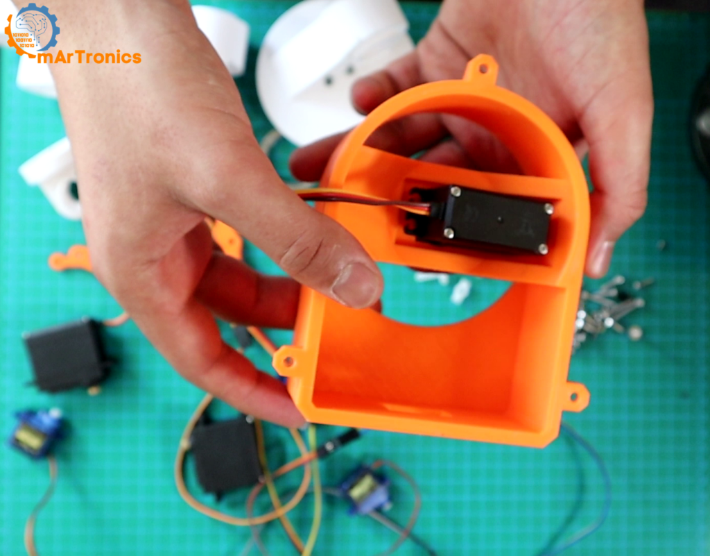
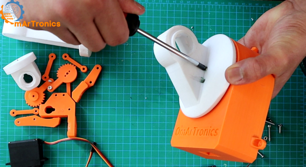
Step 1: Assembling the base
The base is the foundation of the entire arm, so accuracy here matters a lot.
- Securing the servo motor — Install the first MG996R servo into the base mount using the included screws (or M3×12 cross-head self-tapping screws). This servo handles the rotational base movement for the arm.
- Adding the ball bearing (6806ZZ, 30×42×7 mm) — Press-fit the deep-groove ball bearing into its seat on the base. The bearing sits between the fixed base plate and the rotating upper platform, which reduces friction and extends the life of the joint.
- Connecting the servo horn — Attach the servo horn to the rotating upper platform using M2×12 self-tapping screws. Make sure the connection is tight because this horn transmits all rotational force from the servo to the rest of the arm above it.

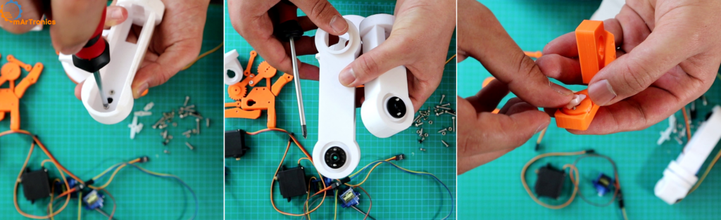
Step 2: Mounting servo horns to arm links
Align each servo horn with its corresponding arm link attachment point, then secure with two screws per horn. Make sure the holes line up perfectly. A misaligned horn will cause binding and uneven movement, so double-check every connection before you tighten fully.
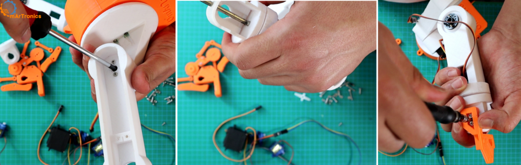
Step 3: Mounting servo motors to arm links
Seat each servo motor into its 3D-printed pocket on the arm link, making sure the orientation is correct. Fasten with two screws per motor and test stability by applying gentle pressure. The servo should not shift or rock at all. A solid motor mount is what gives you precise, repeatable arm movements.
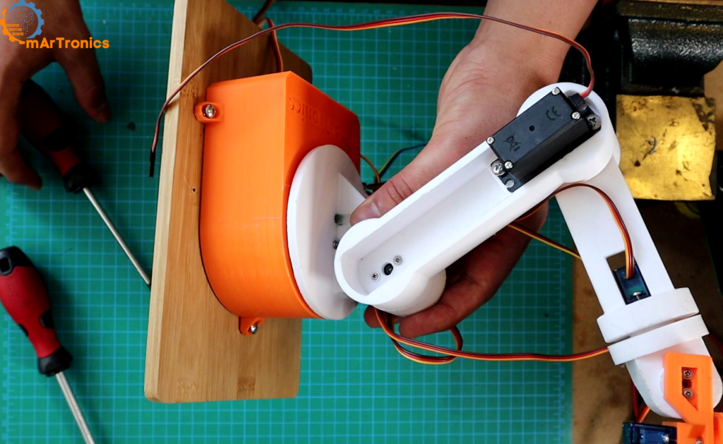
Step 4: Connecting the arm links
Now join the individual link-and-servo assemblies together. Position the horn on one link so it slots into the attachment point of the next link, then secure with screws. Tighten evenly so the joints move smoothly without any play.

Step 5: Assembling the gripper
Attach the gripper sub-assembly to the arm’s end link. The gripper uses an SG90 micro servo with a pair of 3D-printed gears to open and close the fingers. Use M3×20 screws for the gripper joints and make sure the fingers move freely without binding.
Step 6: Securing the arm to a wooden base
Mount the fully assembled arm onto a flat wooden board using M3×12 self-tapping screws. A solid base prevents the arm from tipping during fast movements and gives you a platform for attaching the breadboard and power supply later.

Wiring the 6-DOF robotic arm: Arduino and servo driver
Once the mechanical build is complete, it is time to wire the electronics. The control system has three main pieces: the Arduino Uno (or Mega) as the microcontroller, the PCA9685 servo driver board for generating PWM signals, and six 10 kΩ potentiometers for user input.
Components and wiring guide
- Arduino Uno / Mega — The main controller. It reads potentiometer values and sends I²C commands to the PCA9685.
- PCA9685 Servo Driver Board — An I²C-controlled, 16-channel PWM driver. It handles all six servo signals and leaves room for expansion.
- 5 V 10 A Power Supply — Provides dedicated power to the servos through the PCA9685 V+ terminal. Do not power six servos from the Arduino’s 5 V pin. It cannot supply enough current.
- 6 × 10 kΩ Potentiometers — Connected to Arduino analog pins A0 through A5. Turning a knob changes the voltage, which the Arduino reads as a value from 0 to 1023.
- Breadboard and Jumper Wires — Used to organize the potentiometer connections cleanly.
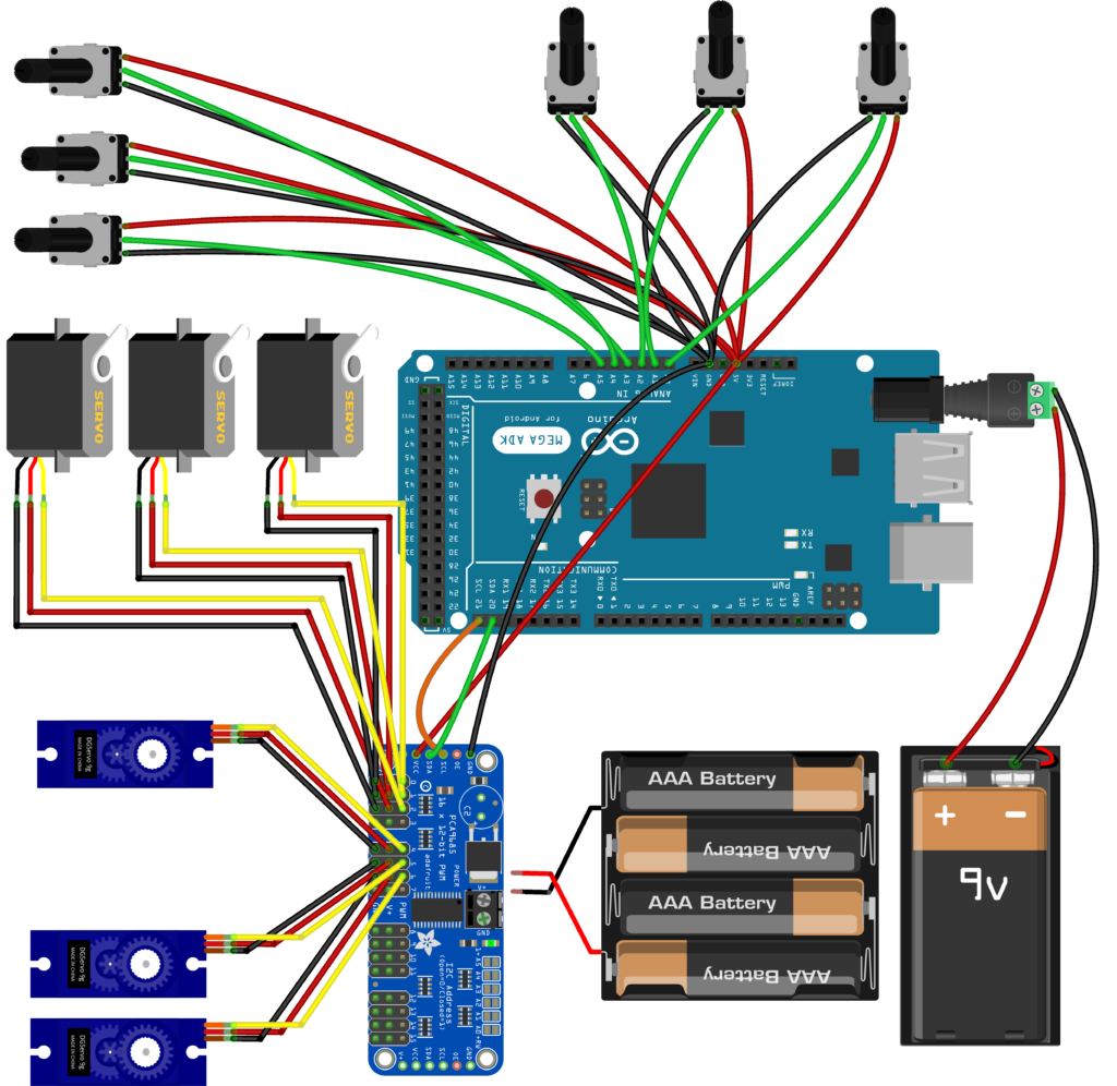
Wiring steps
- PCA9685 → Arduino: Connect VCC to 5 V, GND to GND, SDA to A4, and SCL to A5. On the Mega, SDA and SCL use pins 20 and 21.
- Servos → PCA9685: Plug each servo’s 3-pin connector into channels 0 through 5 on the PCA9685. Make sure the ground wire (brown or black) aligns with the bottom row of headers.
- Potentiometers → Arduino: Wire the outer legs of each pot to 5 V and GND on the breadboard, then connect the center (wiper) pin to A0 through A5.
- Servo Power Supply: Connect the 5 V 10 A supply to the PCA9685 V+ and GND screw terminals. This keeps high servo current completely separate from the Arduino.
Why the 6-DOF robotic arm needs a PCA9685 servo driver
Why not just drive servos straight from the Arduino? You can, but it gets limiting fast. The Arduino Uno only has six PWM-capable pins, and the built-in Servo library can conflict with other timer-dependent features like tone() or certain communication protocols.
The PCA9685 solves this by offloading all PWM generation to a dedicated chip. It communicates over the I²C bus using just two wires (SDA and SCL), no matter how many servos you control. A single board handles 16 channels, and you can daisy-chain up to 62 boards for a theoretical maximum of 992 servos.
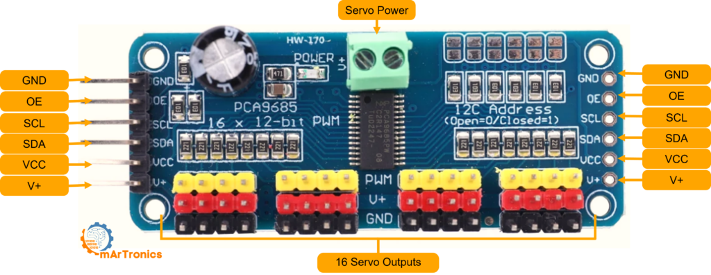
PCA9685 pinout reference
- GND — Common ground, shared with the Arduino.
- OE (Output Enable) — Active low by default. Leave it unconnected to keep all outputs enabled.
- SCL — I²C clock line.
- SDA — I²C data line.
- VCC — Logic power at 3.3 to 5 V. This powers only the PCA9685 chip, not the servos.
- V+ — Servo power rail (up to 6 V). Connect your external supply here through the polarized screw terminal.
Each channel on the board has a 3-pin header that accepts a standard servo connector directly, so wiring is quick and hard to mess up.
Programming the 6-DOF robotic arm for servo control
The Arduino sketch ties everything together. It reads the voltage on each analog pin, converts it to a servo pulse width, and sends the result to the PCA9685. Here is how the logic works.
How the code works
- Library initialization — The sketch includes
Wire.hfor I²C andAdafruit_PWMServoDriver.hfor the PCA9685. Insetup(), it callspwm.begin()and sets the PWM frequency to 60 Hz, which is the standard refresh rate for hobby servos. - Reading the potentiometers — Inside
loop(),analogRead(A0)throughanalogRead(A5)returns a value between 0 and 1023 based on the knob position. - Mapping to servo pulse — The
map()function converts the 0 to 1023 range into a 125 to 575 tick range. These tick values represent the minimum and maximum pulse widths the PCA9685 outputs at 60 Hz (roughly 1 ms to 2.3 ms), which correspond to the servo’s full rotation range. - Setting the PWM output —
pwm.setPWM(channel, 0, ticks)sends the computed pulse to the correct PCA9685 channel. The second parameter (0) is the “on” tick, and the third is the “off” tick within the 4096-step PWM cycle. - Loop delay — A 20 ms delay at the end of each loop keeps the refresh rate smooth and avoids flooding the I²C bus.
Upload the following sketch to your Arduino Uno (or Mega). Make sure the Adafruit PWM Servo Driver Library is installed through the Arduino Library Manager before compiling.
Arduino sketch: full source code
/**
 * Author: Omar Draidrya
 * Date: 2024/05/05
 * Controls 6 servos via PCA9685 with potentiometer input.
 */
#include <Wire.h>
#include <Adafruit_PWMServoDriver.h>
Adafruit_PWMServoDriver pwm = Adafruit_PWMServoDriver(); // Default address 0x40
void setup() {
    Serial.begin(9600);           // Init serial for debugging
    pwm.begin();                  // Init PCA9685
    pwm.setPWMFreq(60);           // 60 Hz for servos
}
void loop() {
    // Servo 0
    int potValue0 = analogRead(A0);           // Read A0
    int servoPos0 = map(potValue0, 0, 1023, 125, 575); // Map to pulse range
    pwm.setPWM(0, 0, servoPos0);              // Set servo 0
    // Servo 1
    int potValue1 = analogRead(A1);           // Read A1
    int servoPos1 = map(potValue1, 0, 1023, 125, 575); // Map to pulse range
    pwm.setPWM(1, 0, servoPos1);              // Set servo 1
    // Servo 2
    int potValue2 = analogRead(A2);           // Read A2
    int servoPos2 = map(potValue2, 0, 1023, 125, 575); // Map to pulse range
    pwm.setPWM(2, 0, servoPos2);              // Set servo 2
    // Servo 3
    int potValue3 = analogRead(A3);           // Read A3
    int servoPos3 = map(potValue3, 0, 1023, 125, 575); // Map to pulse range
    pwm.setPWM(3, 0, servoPos3);              // Set servo 3
    // Servo 4
    int potValue4 = analogRead(A4);           // Read A4
    int servoPos4 = map(potValue4, 0, 1023, 125, 575); // Map to pulse range
    pwm.setPWM(4, 0, servoPos4);              // Set servo 4
    // Servo 5
    int potValue5 = analogRead(A5);           // Read A5
    int servoPos5 = map(potValue5, 0, 1023, 125, 575); // Map to pulse range
    pwm.setPWM(5, 0, servoPos5);              // Set servo 5
    delay(20);   // Small delay for smooth updates
}
Required libraries
Before compiling, install these libraries through the Arduino IDE Library Manager: Adafruit PWM Servo Driver Library and Wire (included by default). Then select your board (Arduino Uno or Mega), choose the correct COM port, and click Upload.
Calibrating and testing your 6-DOF robotic arm
Once your 6-DOF robotic arm is fully wired, power on the servo supply and slowly turn each potentiometer. You should see the matching joint move in real time. If a joint moves the wrong way, swap the outer wires on that potentiometer to reverse the direction.
Fine-tune the map() range values (125 and 575) for each servo individually. Some servos may need slightly different minimum and maximum tick values to avoid buzzing at the mechanical end stops. Test the arm under load by picking up small objects with the gripper to confirm torque and stability.
What to do next with your 6-DOF robotic arm
You now have a working DIY 6-DOF robotic arm built from scratch. This project touches every core area of mechatronics: CAD design, additive manufacturing, electronic wiring, and embedded programming.
From here, you could add inverse kinematics for automated positioning, integrate a Bluetooth module for wireless control (we did that in our Bluetooth-controlled robotic arm upgrade), or teach the arm to record and replay movement sequences. This six-axis platform is a good starting point for going deeper into robotics and automation.
Download the 3D print files (STL)
All 3D-printable STL files for this project are available for download. You can get them from our shop or browse them on Cults3D:
- OmArTronics Shop: Download project files from OmArTronics — Get the complete project package including STL files, wiring diagrams, and source code delivered to your email.
- Cults3D: View on Cults3D — Browse and download the 3D model files on Cults3D.
can u tell how to connect potentiometer with bread board
I am building an AI Robot and want to use your robotic arm in the build. I want to mount it on the front side vertically. I noticed on past photos there was a tension spring attached to the rotating base to the first arm piece but not listed in the parts list or build instructions. I wish to implement the spring back into the build because of its vertical placement on my robot. Can you provide me with the specifications for the spring? This robotic arm is in my opinion is one of the better designed and documented arms of its type out on the web.
Thanks a lot! I’m glad you liked the design
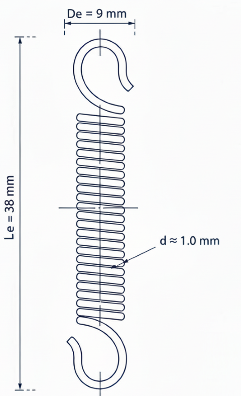
Yes, that tension spring connects the rotating base to the first arm segment to help support the shoulder joint, especially when the arm is mounted vertically.
The spring is about 2 cm long (at rest) and 9 mm in diameter.
I actually reused it from an old desk lamp stand, but you can find similar extension springs easily online or in hardware stores.
It’s optional but really helps balance the arm and reduce servo stress.
Hello! I wanted to ask the function of the atachment points on the base and the first link, are they for a spring? it is modelled but the pictures of the assembly don’t have this feature, nor is it referenced on the post. Thank you! this is a nice design
Yes, those points are for a spring. The spring is optional — it helps the shoulder joint carry part of the arm’s weight.
This feature was added in a later version of the design.
You can also use a rubber band, but I personally prefer a spring.
The one I used is about 2 cm long (at rest) and 9 mm in diameter.
I actually took it from an old desk lamp stand, but you can easily find similar springs online or in hardware stores.