
Want to make a servo motor move precisely to any angle with your Arduino? Whether you are building a robotic arm, a pan-tilt camera mount, or an automated door lock, Arduino servo control is one of the most essential skills in electronics and robotics. However, many beginners struggle with jittery servos, incorrect wiring, and confusion about PWM signals and power requirements.
In this comprehensive tutorial, you will learn exactly how servo motors work, how to wire and program an SG90 or MG996R servo with Arduino, and how to scale up to controlling multiple servos using the PCA9685 driver board. By the end, you will have completed three hands-on projects and gained the confidence to integrate servos into any robotics project.
Furthermore, all wiring diagrams and code examples are included, so you can follow along step by step. If you want to see these projects in action, check out the video tutorial above.
What You Will Learn in This Arduino Servo Tutorial
By the end of this guide, you will be able to:
- Understand how servo motors work internally (DC motor, gears, potentiometer feedback, and closed-loop control)
- Explain how PWM signals control servo position at 50 Hz
- Compare SG90 and MG996R servos and choose the right one for your project
- Wire and program an Arduino servo sweep project from scratch
- Control a servo with a potentiometer using analogRead and map functions
- Use the PCA9685 servo driver to control up to 16 servos simultaneously
- Power multiple servos safely without damaging your Arduino
- Troubleshoot common servo problems like jitter, overheating, and brownouts
How Servo Motors Work: The Basics
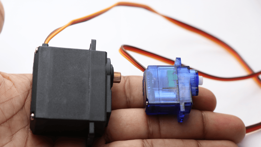
A servo motor is a special type of motor designed to rotate to a specific angle and hold that position. Unlike a standard DC motor that simply spins continuously, a servo uses a closed-loop feedback system to achieve precise angular control. As a result, servos are ideal for applications where exact positioning matters, such as robotic arms, steering mechanisms, and camera gimbals.
Internal Components of a Servo Motor
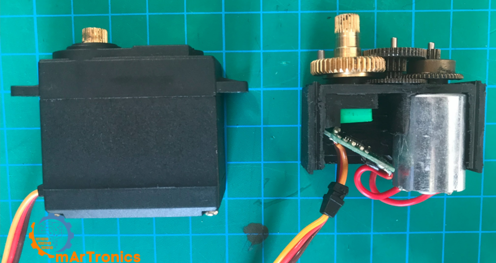
If you open up a typical hobby servo, you will find four main components working together:
- DC Motor: This is the core actuator that converts electrical energy into rotational motion. It provides the raw spinning force.
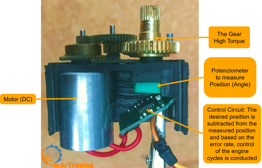
- Gear Train: A set of reduction gears (plastic in the SG90, metal in the MG996R) that reduces the motor’s high RPM down to a slower, higher-torque output at the output shaft.
- Potentiometer: A small variable resistor connected to the output shaft. It continuously reports the shaft’s current angle back to the control circuit.
- Control Circuit: A small PCB inside the servo that compares the desired position (from the PWM signal) with the actual position (from the potentiometer) and drives the motor to close the gap.
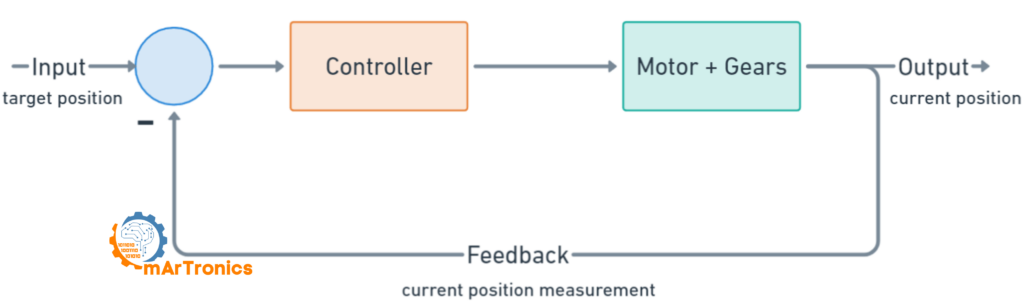
Closed-Loop Control: How the Servo Knows Where to Go
The key principle behind every servo is closed-loop control. Here is how the process works step by step:
- The Arduino sends a PWM signal that encodes the desired angle.
- The servo’s control circuit reads the pulse width and calculates the target position.
- The control circuit reads the potentiometer to determine the shaft’s current position.
- If there is a difference between the target and the current position, the circuit drives the DC motor in the correct direction.
- Once the potentiometer reading matches the target, the motor stops and holds position.
Consequently, the servo continuously corrects itself, maintaining the exact angle even under external load. This feedback loop is what makes servos so reliable for robotics applications.
Servo PWM Signal Explained: How Pulse Width Controls Angle
Pulse Width Modulation (PWM) is the language that Arduino uses to communicate with servo motors. Instead of sending a voltage level, the Arduino sends a series of digital pulses at a fixed frequency, and the width of each pulse tells the servo which angle to move to.
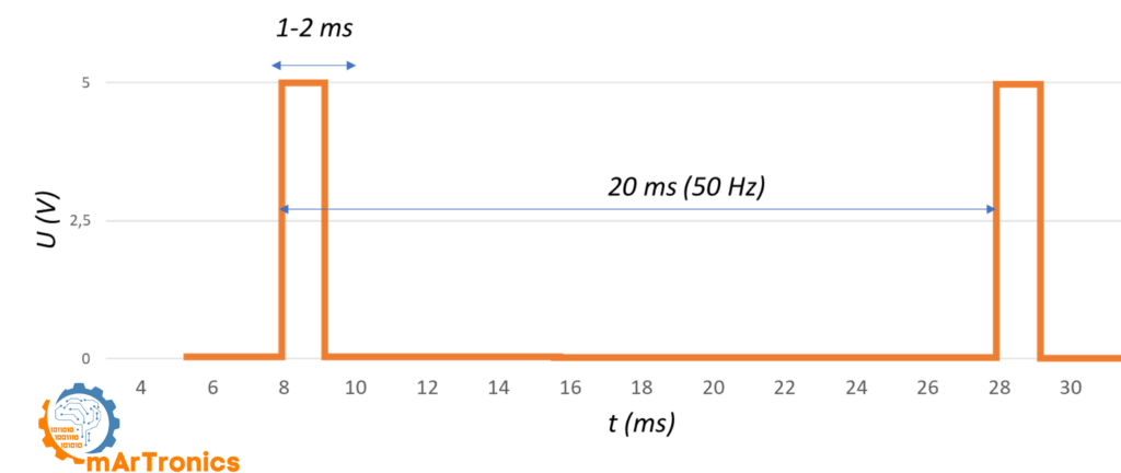
For standard hobby servos, the PWM signal operates at 50 Hz, which means one pulse is sent every 20 milliseconds. Within each 20 ms period, only the duration of the HIGH portion (the pulse width) matters. Typically, a pulse width between 1.0 ms and 2.0 ms maps to the full range of servo motion from 0 to 180 degrees.
PWM Pulse Width vs Servo Position Table
The following table shows how different pulse widths correspond to specific servo positions. Keep in mind that exact values can vary slightly between servo models:
| Pulse Width (ms) | Servo Position | Duty Cycle at 50 Hz |
|---|---|---|
| 0.5 ms | 0° (minimum, some servos) | 2.5% |
| 1.0 ms | 0° (standard minimum) | 5% |
| 1.25 ms | 45° | 6.25% |
| 1.5 ms | 90° (center position) | 7.5% |
| 1.75 ms | 135° | 8.75% |
| 2.0 ms | 180° (standard maximum) | 10% |
| 2.5 ms | 180° (maximum, some servos) | 12.5% |
As a result, the Arduino Servo library abstracts most of this complexity. When you call servo.write(90), the library automatically generates a 1.5 ms pulse at 50 Hz to move the servo to center position. However, understanding the underlying PWM signal is essential for troubleshooting jitter, calibrating custom ranges, and working with the PCA9685 driver.
SG90 vs MG996R: Choosing the Right Servo for Your Project
ال SG90 micro servo و MG996R standard servo are the two most popular hobby servos used in Arduino projects. Choosing between them depends on your project’s torque, size, and durability requirements. The table below provides a detailed side-by-side comparison:

| Specification | محرك سيرفو صغير SG90 | محرك سيرفو MG996R |
|---|---|---|
| Stall Torque | 1.2 kg·cm at 4.8 V, 1.6 kg·cm at 6 V | 11 kg·cm at 4.8 V, 13 kg·cm at 6 V |
| جهد التشغيل | 3.5 to 6 V | 4.8 to 7.2 V |
| No-Load Current | 100 mA | 220 mA at 4.8 V, 250 mA at 6 V |
| Stall Current | 650 mA | 900 mA at 4.8 V, 1400 mA at 6 V |
| Operating Speed | 0.12 s per 60° at 4.8 V | 0.15 s per 60° at 4.8 V |
| Weight | 9 g | 55 g |
| Gear Type | Plastic gears | Metal gears |
| Rotation Range | 180° | 180° |
| Ideal Use Case | Lightweight projects, pan-tilt, small robots | Robotic arms, high-load joints, RC vehicles |
| Pros | Cheap, lightweight, low power draw | High torque, durable metal gears, precise |
| Cons | Low torque, plastic gears can strip | Heavier, higher current draw, more expensive |
In summary, use the SG90 when weight and space are limited and loads are light. Choose the MG996R when you need serious torque, for example in a مشروع ذراع روبوتية بست درجات حرية where the shoulder and elbow joints carry significant load. Many robotic arm builds, including ours, use a combination of both: MG996R for the heavy base joints and SG90 for the lighter wrist and gripper.
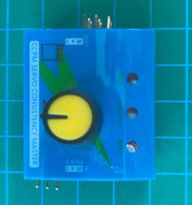
Servo Testers: A Useful Calibration Tool
Before wiring a servo to your Arduino, a servo tester is a handy standalone tool for quickly verifying that a servo works correctly. These inexpensive modules (typically just a few dollars) let you sweep through the full range or set specific positions using a knob, without needing any code or microcontroller. They are especially useful when calibrating multiple servos for a robotics project.
Powering Servos Safely: Current Draw and External Supplies
One of the most common mistakes beginners make is powering servos directly from the Arduino’s 5 V pin. While this may work for a single SG90 under light load, it is not recommended for most projects. Here is why, and what to do instead.
Why Not Power Servos from the Arduino 5 V Pin?
The Arduino Uno’s 5 V regulator can supply only about 500 mA of current in total. A single SG90 servo can draw up to 650 mA at stall, and an MG996R can draw up to 1400 mA. Therefore, if the servo demands more current than the regulator can provide, you may experience voltage drops that cause the Arduino to reset or behave unpredictably.
External Power Supply Recommendations
To power servos reliably, use a dedicated external power supply rated at 5 V to 6 V with enough current capacity. For example, a 5 V 2 A adapter works well for one or two SG90 servos, while a 5 V 10 A power supply is better for projects with six or more servos, such as a robotic arm.
Additionally, always follow these critical wiring rules for Arduino servo motor control:
- Common Ground: Connect the ground of the external power supply to the Arduino GND. Without a common ground, the PWM signal has no reference and the servo will not respond correctly.
- Separate Power Rails: Connect the servo’s red (power) wire to the external supply’s positive terminal, not to the Arduino 5 V pin.
- Signal Wire Only: The only connection between the Arduino and the servo should be the signal (PWM) wire.
- Decoupling Capacitors: Place a 100 uF electrolytic capacitor across the power rails near the servos to reduce voltage spikes and jitter.
Current Draw Quick Reference
| Servo Model | No-Load Current | Stall Current | Recommended Supply per Servo |
|---|---|---|---|
| SG90 | 100 mA | 650 mA | 5 V, at least 1 A |
| MG996R | 220 mA | 1400 mA | 6 V, at least 2 A |
Consequently, for a project with six servos running simultaneously, the total peak current can exceed 3 A or more. This is why a robust external power supply is absolutely essential for any serious Arduino servo project.
Servo Motor Wiring: Understanding the Three Wires
Before connecting your servo to an Arduino, it is important to understand the three-wire connector that all standard hobby servos use:
| Pin | Signal | Wire Color |
|---|---|---|
| 1 | Ground (GND) | Black or Brown |
| 2 | Power (VCC, 4.8 to 6 V) | Red |
| 3 | Control Signal (PWM) | Orange or Yellow |
Most servos use this same standard regardless of manufacturer. The ground wire is always on one edge, power in the middle, and signal on the other edge. Always double-check the datasheet if you are unsure about a particular servo model.
Project 1: Arduino Servo Sweep – Your First Servo Project
The Sweep sketch is the classic beginner project for Arduino servo control. It makes the servo continuously rotate back and forth between 0 and 180 degrees. This project teaches you the basics of the Arduino Servo library and confirms that your wiring is correct.
Parts Needed for the Sweep Project
- Arduino Uno (or any Arduino board)
- SG90 micro servo (or similar)
- External 5 V power supply for the servo (recommended)
- Breadboard and jumper wires
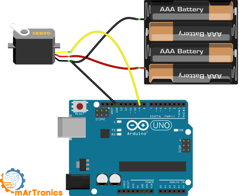
Sweep Wiring Connections
| سلك المؤازرة | يتصل بـ |
|---|---|
| Brown or Black (GND) | Arduino GND and external supply GND |
| Red (VCC) | External 5 V supply positive |
| Orange or Yellow (Signal) | Arduino digital pin 9 |
Sweep Arduino Code
Open the Arduino IDE and go to File, Examples, Servo, Sweep, or copy the code below. The Sweep example is included in the standard Arduino Servo library.
/* Sweep
 by BARRAGAN http://barraganstudio.com
 This example code is in the public domain.
 modified 8 Nov 2013
 by Scott Fitzgerald
 https://www.arduino.cc/en/Tutorial/LibraryExamples/Sweep
 */
#include <Servo.h>
Servo myservo;  // create servo object to control a servo
// twelve servo objects can be created on most boards
int pos = 0;    // variable to store the servo position
void setup() {
    myservo.attach(9);  // attaches the servo on pin 9 to the servo object
}
void loop() {
    for (pos = 0; pos <= 180; pos += 1) { // goes from 0 degrees to 180 degrees
        // in steps of 1 degree
        myservo.write(pos);              // tell servo to go to position in variable 'pos'
        delay(15);                       // waits 15 ms for the servo to reach the position
    }
    for (pos = 180; pos >= 0; pos -= 1) { // goes from 180 degrees to 0 degrees
        myservo.write(pos);              // tell servo to go to position in variable 'pos'
        delay(15);                       // waits 15 ms for the servo to reach the position
    }
}
How the Sweep Code Works Line by Line
The Sweep sketch is short but demonstrates all the essential concepts for servo motor PWM Arduino control:
#include <Servo.h>– This line imports the Arduino Servo library, which handles all the PWM timing for you.Servo myservo;– This creates a Servo object. You can create up to 12 servo objects on an Arduino Uno.myservo.attach(9);– This tells the library to send PWM signals on digital pin 9.myservo.write(pos);– This command moves the servo to the angle stored in the variablepos. The value ranges from 0 to 180.- The two
forloops sweep the angle from 0 to 180 and then back from 180 to 0, with a 15 ms delay between each step for smooth motion.
If the servo moves in the wrong direction or does not reach the full range, try adjusting the delay or check your power supply. Similarly, if you notice jitter at the endpoints, it may indicate that the servo cannot physically reach those angles.
Project 2: Controlling a Servo with a Potentiometer (Knob)
The Knob project takes Arduino servo motor control a step further by adding a potentiometer as an input device. Turning the knob directly controls the servo angle in real time. This project teaches you how to read analog inputs and map them to servo positions, a pattern you will use in countless robotics projects.
Parts Needed for the Knob Project
- Arduino Uno (or any Arduino board)
- SG90 micro servo (or similar)
- 10 kOhm potentiometer
- External 5 V power supply for the servo (recommended)
- Breadboard and jumper wires
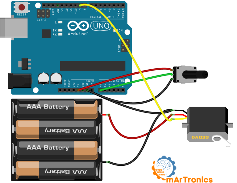
Knob Wiring Connections
| عنصر | Pin or Wire | يتصل بـ |
|---|---|---|
| Servo GND (Brown/Black) | أرضي | Arduino GND and external supply GND |
| Servo VCC (Red) | VCC | External 5 V supply positive |
| Servo Signal (Orange/Yellow) | Signal | Arduino digital pin 9 |
| Potentiometer pin 1 | Outer pin | Arduino 5 V |
| Potentiometer wiper | Middle pin | Arduino analog pin A0 |
| Potentiometer pin 3 | Outer pin | أرضي أردوينو |
Knob Arduino Code
Open the Arduino IDE and go to File, Examples, Servo, Knob, or use the code below:
/*
 Controlling a servo position using a potentiometer (variable resistor)
 by Michal Rinott http://people.interaction-ivrea.it/m.rinott
 modified on 8 Nov 2013
 by Scott Fitzgerald
 http://www.arduino.cc/en/Tutorial/Knob
 */
#include <Servo.h>
Servo myservo;  // create servo object to control a servo
int potpin = A0;  // analog pin used to connect the potentiometer
int val;    // variable to read the value from the analog pin
void setup() {
    myservo.attach(9);  // attaches the servo on pin 9 to the servo object
}
void loop() {
    val = analogRead(potpin);            // reads the value of the potentiometer (value between 0 and 1023)
    val = map(val, 0, 1023, 0, 180);     // scale it for use with the servo (value between 0 and 180)
    myservo.write(val);                  // sets the servo position according to the scaled value
    delay(15);                           // waits for the servo to get there
}
How the Knob Code Works: analogRead and map
The key functions in this sketch are analogRead() و رسم خريطة():
analogRead(A0)– Reads the potentiometer voltage and returns a value between 0 and 1023 (10-bit ADC resolution).map(val, 0, 1023, 0, 180)– Converts the 0 to 1023 range to a 0 to 180 degree range suitable for the servo.myservo.write(val)– Sends the mapped angle to the servo.
If you want finer control over the servo position, you can use myservo.writeMicroseconds() instead of myservo.write(). This lets you specify the pulse width directly in microseconds (for example, 1000 to 2000), giving you much higher resolution than the 0 to 180 degree range. Additionally, if the servo does not reach the full range when you turn the potentiometer all the way, adjust the map values slightly, for example map(val, 0, 1023, 10, 170).
PCA9685 Servo Driver: Control Up to 16 Servos with Arduino
Controlling one or two servos directly from Arduino pins works well, but what happens when you need more? The Arduino Uno has only six PWM-capable pins, and each servo consumes one. Furthermore, using more than a couple of servos can cause timing conflicts and jitter. This is where the PCA9685 servo driver becomes essential.
What Is the PCA9685 and Why Use It?
The PCA9685 is a 16-channel, 12-bit PWM driver chip that communicates with Arduino over the I2C bus. Instead of using Arduino PWM pins, the PCA9685 generates all 16 PWM signals independently. As a result, you free up Arduino pins for sensors and other tasks, and the dedicated hardware PWM produces rock-steady signals with zero jitter.
Additionally, you can daisy-chain up to 62 PCA9685 boards on a single I2C bus, giving you a theoretical maximum of 992 servo channels. However, for most projects, a single board with 16 channels is more than enough.
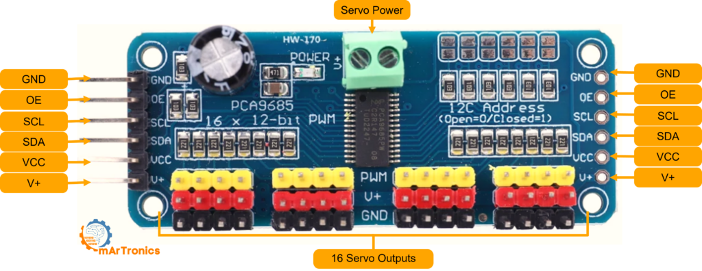
PCA9685 Board Connections Explained
The PCA9685 breakout board has the following main connections:
- VCC: Logic power (3.3 V or 5 V from Arduino). This powers only the PCA9685 chip, not the servos.
- GND: Ground, must be shared with Arduino and the servo power supply.
- SDA: I2C data line. Connect to Arduino A4 (Uno) or the SDA pin.
- SCL: I2C clock line. Connect to Arduino A5 (Uno) or the SCL pin.
- V+: Servo power input. Connect an external 5 V to 6 V supply here. This powers all 16 servo channels.
- OE: Output enable. Leave disconnected (pulled LOW internally) to keep all outputs active.
When to Use PCA9685 Instead of Direct Arduino Control
Use the PCA9685 when you need to control multiple servos with Arduino (more than two or three), when you want jitter-free motion, or when your project needs the remaining Arduino PWM pins for other purposes like LED dimming or motor speed control. For simple single-servo projects, direct Arduino control is perfectly fine.
Project 3: Dual Servo Control with PCA9685 and Potentiometers
This project demonstrates how to control two servos independently using a PCA9685 driver board and two potentiometers. It combines everything you have learned about analog input, servo PWM, and I2C communication into one practical build.
Parts Needed for the PCA9685 Dual Servo Project
| عنصر | كمية |
|---|---|
| أردوينو أونو | 1 |
| لوحة تشغيل محرك سيرفو PCA9685 | 1 |
| SG90 micro servo (or similar) | 2 |
| 10 kOhm potentiometer | 2 |
| External 5 V or 6 V power supply (at least 2 A) | 1 |
| Breadboard and jumper wires | حسب الحاجة |
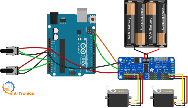
PCA9685 Dual Servo Wiring
| اتصال | From | To |
|---|---|---|
| I2C Data | Arduino A4 (SDA) | PCA9685 SDA |
| I2C Clock | Arduino A5 (SCL) | PCA9685 SCL |
| Logic Power | Arduino 5 V | PCA9685 VCC |
| Common Ground | أرضي أردوينو | PCA9685 GND and external supply GND |
| Servo Power | External 5 V supply positive | PCA9685 V+ terminal |
| Servo 1 | 3-pin connector | PCA9685 channel 0 |
| Servo 2 | 3-pin connector | PCA9685 channel 15 |
| Potentiometer 1 wiper | Middle pin | Arduino A0 |
| Potentiometer 2 wiper | Middle pin | Arduino A1 |
| Potentiometer outer pins | Outer pins | Arduino 5 V and GND |
PCA9685 Dual Servo Arduino Code
This sketch uses the Adafruit PWM Servo Driver library. Install it from the Arduino Library Manager by searching for “Adafruit PWM Servo Driver”. The code reads both potentiometers and maps their values to servo pulse widths:
/**
 * Author: Omar Draidrya
 * Date: 2024/05/07
 * This code controls servos using the PCA9685 PWM driver and potentiometers.
 */
#include <Wire.h>
#include <Adafruit_PWMServoDriver.h>

// Initialize the PCA9685 using the default address (0x40).
Adafruit_PWMServoDriver pwm = Adafruit_PWMServoDriver();

void setup() {
    Serial.begin(9600);   // Start serial communication for debugging purposes.
    pwm.begin();          // Initialize the PCA9685 module.

    // Set the frequency to 60 Hz, good for servo control.
    pwm.setPWMFreq(60);

    // Setup the analog pins as input.
    pinMode(A0, INPUT);
    pinMode(A1, INPUT);
}

void loop() {
    // Read the potentiometers.
    int potVal0 = analogRead(A0);  // Read the first potentiometer.
    int potVal1 = analogRead(A1);  // Read the second potentiometer.

    // Map the potentiometer values to servo pulse lengths.
    int servoPos0 = map(potVal0, 0, 1023, 150, 600); // Change values 150 to 600 depending on your servo specifications.
    int servoPos1 = map(potVal1, 0, 1023, 150, 600);

    // Set the servo positions.
    pwm.setPWM(0, 0, servoPos0);   // Set servo on channel 0.
    pwm.setPWM(15, 0, servoPos1);  // Set servo on channel 15.

    delay(20);  // Small delay to reduce jitter.
}
Understanding the PCA9685 Pulse Range Values
In the code above, you will notice values like 150 and 600 passed to setPWM(). These are not degrees or milliseconds. Instead, they represent the 12-bit PWM count out of 4096 total ticks per cycle. A value of 150 corresponds to approximately 0.73 ms pulse width, and 600 corresponds to approximately 2.93 ms. For most standard servos, a range of 150 to 600 covers the full 0 to 180 degree rotation. However, you may need to fine-tune these values for your specific servo to avoid end-stop buzzing.
To test the setup, upload the code and slowly turn each potentiometer. Verify that each servo responds independently. If a servo does not move, double-check the I2C connections and ensure the external power supply is connected to V+ on the PCA9685 board.
Troubleshooting Common Arduino Servo Problems
Even experienced makers run into servo issues from time to time. The following section covers the most common problems and their solutions, so you can diagnose and fix issues quickly.
Servo Jitter or Twitching
If your servo vibrates or twitches instead of holding a steady position, the most likely cause is an unstable power supply. Specifically, when the servo draws current spikes, the supply voltage drops momentarily, causing the control circuit to lose its reference. To fix this, use a dedicated external power supply with adequate current capacity and add a 100 uF to 470 uF electrolytic capacitor across the servo power rails. Additionally, noisy PWM signals from software-based servo control can also cause jitter, which is another reason to consider using the PCA9685 hardware PWM driver.
Servo Not Moving at All
If the servo does not respond to commands, check the following: verify that the signal wire is connected to the correct PWM-capable Arduino pin, confirm that the ground is shared between the Arduino and the servo power supply, and ensure the power supply is actually turned on and delivering the correct voltage. Moreover, make sure the Servo library is included and the servo is properly attached in your code with servo.attach(pin).
Servo Overheating
Servo overheating typically occurs when the motor is stalled, meaning it is trying to hold a position against a load that exceeds its torque rating. In this condition, the motor continuously draws stall current, which generates significant heat. To prevent overheating, reduce the mechanical load, use a higher-torque servo, or add rest periods in your code by detaching the servo when it does not need to hold position. For example, calling servo.detach() stops the PWM signal and allows the motor to relax.
Noisy Power Supply and Voltage Brownouts
When multiple servos move simultaneously, the combined current draw can cause voltage sags on a weak power supply. Consequently, the Arduino may reset, LEDs may flicker, or servos may move erratically. The solution is to use a power supply with a higher current rating and to add bulk capacitance (at least 470 uF) near the servos. In addition, keep the power supply wires as short and thick as possible to minimize voltage drop.
Wrong Pulse Range or Limited Rotation
If your servo does not reach the full 0 to 180 degree range, the issue is likely the pulse width limits in your code. Different servo models may have slightly different pulse ranges. For direct Arduino control, you can specify custom limits with servo.attach(pin, minPulse, maxPulse), for example servo.attach(9, 544, 2400). For the PCA9685, adjust the minimum and maximum PWM count values (for instance, 125 to 625 instead of 150 to 600).
Wrong Ground Wiring
Without a common ground between the Arduino and the servo power supply, the PWM signal has no valid reference voltage. As a result, the servo may ignore commands entirely or behave unpredictably. Always connect all ground wires together, whether you are using a single power source or separate supplies for logic and servos.
Frequently Asked Questions About Arduino Servo Control
How many servos can I control with one Arduino Uno?
With the standard Arduino Servo library, you can control up to 12 servos on an Arduino Uno. However, each servo uses a timer resource, and using many servos may interfere with other timer-dependent functions like PWM output on certain pins. If you need more servos, a PCA9685 driver board adds 16 channels per board with no timer conflicts.
Can I use a servo motor without a library?
Yes, it is technically possible to generate the PWM signal manually using digitalWrite() و delayMicroseconds(). However, this approach is not recommended because it is less precise, blocks the CPU during timing loops, and is harder to maintain. The Servo library handles all timing details automatically.
What is the difference between servo.write() and servo.writeMicroseconds()?
ال servo.write() function accepts an angle from 0 to 180 degrees and converts it internally to a pulse width. In contrast, servo.writeMicroseconds() lets you specify the exact pulse width (typically 1000 to 2000 microseconds), giving you finer control over position. Use writeMicroseconds when you need precision beyond one-degree increments.
Why does my servo buzz or vibrate at certain positions?
Buzzing usually occurs when the servo is at or near its mechanical limit, or when the signal is slightly unstable. The control loop continuously tries to correct a tiny position error, causing rapid oscillation. To fix this, adjust your pulse range to avoid the extreme ends, use a stable power supply, and consider adding a small dead band in your code.
Can I power a servo from a 9 V battery?
A standard 9 V battery is not recommended for servo motors. Most hobby servos require 4.8 to 6 V, and a 9 V battery would either need a voltage regulator or could damage the servo. Additionally, 9 V batteries have very limited current capacity (typically only 500 mAh), which means they cannot sustain the high current draw of a servo for more than a few minutes.
What does PCA9685 stand for?
PCA9685 is the part number assigned by NXP Semiconductors. It stands for a 16-channel, 12-bit PWM and LED controller IC with I2C bus interface. In the maker community, it is most commonly used as a servo driver, but it can also control LEDs and other PWM devices.
Can I use MG996R and SG90 servos together in the same project?
Absolutely. In fact, many robotic arm projects use MG996R servos for the high-torque base and shoulder joints, and SG90 servos for the lighter wrist and gripper joints. Just make sure your power supply can handle the combined current draw of all servos.
How do I control a continuous rotation servo with Arduino?
Continuous rotation servos work differently from standard position servos. Instead of controlling the angle, the pulse width controls the speed and direction of rotation. A 1.5 ms pulse stops the motor, pulses shorter than 1.5 ms spin it one direction, and pulses longer than 1.5 ms spin it the other direction. You can still use the Servo library; servo.write(90) stops, servo.write(0) is full speed one way, and servo.write(180) is full speed the other way.
Why does my Arduino reset when the servo moves?
This happens when the servo’s current draw causes a voltage drop on the Arduino’s power supply. Essentially, the Arduino’s built-in voltage regulator cannot supply enough current for both the board and the servo simultaneously. The solution is simple: power the servo from a separate external supply and share only the ground connection with the Arduino.
Can I control a servo over Bluetooth with Arduino?
Yes. By adding an HC-05 or HC-06 Bluetooth module to your Arduino, you can send servo angle commands wirelessly from a smartphone or computer. The Arduino receives the commands via serial communication and moves the servo accordingly. For a complete Bluetooth servo control tutorial, see our HC-05 Bluetooth module guide and our Bluetooth robotic arm project.
Resources, Libraries, and Downloads
Here is a quick reference of all the tools, libraries, and files you need for the projects in this tutorial:
Arduino Libraries Used
- Servo.h – Built into the Arduino IDE. No installation needed. Used for Project 1 (Sweep) and Project 2 (Knob).
- Adafruit PWM Servo Driver – Install from the Arduino Library Manager. Search for “Adafruit PWM Servo Driver”. Used for Project 3 (PCA9685 Dual Servo).
- Wire.h – Built into the Arduino IDE. Required for I2C communication with the PCA9685.
Code Download and Wiring Diagrams
All three project codes are included directly in this article above. You can also find the source files and wiring diagrams on our مستودع GitHub. Furthermore, every wiring diagram shown in this tutorial is available as a high-resolution image that you can download by right-clicking and saving.
Recommended Next Tutorials on OmArTronics
Once you are comfortable with basic Arduino servo control, consider exploring these more advanced projects:
- DIY 6-DOF Robotic Arm Build – Build a complete robotic arm using six servos controlled by potentiometers.
- Bluetooth-Controlled Robotic Arm – Add wireless Bluetooth control to your robotic arm using an HC-05 module and a custom Android app.
- Servo Control with Joystick and OLED Display – Control servos using a joystick with real-time position feedback on an OLED screen.
- Mobile Robot Arm (OmObiArm) – Combine a robotic arm with a mobile rover base for a fully mobile manipulation platform.
- HC-05 Bluetooth Module Complete Tutorial – Learn everything about Bluetooth serial communication with Arduino.
Conclusion: Your Arduino Servo Control Journey
In this tutorial, you have learned how servo motors work from the inside out, including the DC motor, gear train, potentiometer feedback, and closed-loop control system. You now understand how PWM signals at 50 Hz translate pulse width into precise angular position. Moreover, you have completed three practical projects: the Sweep sketch for basic motion, the Knob project for analog input control, and the PCA9685 dual servo project for scaling up to multiple servos.
Along the way, you also learned how to choose between the SG90 and MG996R servos, how to power servos safely with external supplies, and how to troubleshoot common issues like jitter, brownouts, and overheating. These are fundamental skills that you will use in virtually every robotics project you build.
Your next step is to apply what you have learned to a real project. Building a DIY robotic arm is one of the best ways to solidify your servo control skills, and our step-by-step guide will walk you through the entire process. Welcome to the world of robotics!
3 رأي حول “Arduino Servo Control Guide: SG90, PWM, and PCA9685”