
ملخص سريع
Arduino servo motor guide covering SG90 micro servos, PWM signal basics, and multi-servo control with the PCA9685 I2C driver. Walks through wiring servos directly to Arduino pins, controlling angle with the Servo library, and scaling up to 16 or more servos using the PCA9685 module. Tested code for all configurations included.
هل ترغب في تحريك محرك سيرفو بدقة إلى أي زاوية باستخدام أردوينو؟ سواء كنت تقوم ببناء ذراع روبوتية، أو حامل كاميرا متحرك، أو قفل باب آلي،, التحكم في محرك سيرفو باستخدام أردوينو is one of the first skills worth learning. Yet many beginners run into the same problems: jittery movement, wrong wiring, and confusion about PWM signals and power requirements.
In this tutorial, you will learn how servo motors actually work on the inside, how to wire and program an SG90 or MG996R servo with Arduino, and how to scale up to controlling multiple servos with a PCA9685 driver board. As a result, by the end you will have completed three hands-on projects and gained enough confidence to put servos into any build.
In addition, all wiring diagrams and code examples are included below, so you can follow along step by step. And if you want to see these projects in action, there is a video tutorial at the top of this page.
What this servo tutorial covers
Specifically, by the end of this guide you will be able to:
- فهم كيفية عمل محركات المؤازرة داخليًا (محرك التيار المستمر، والتروس، وتغذية مقياس الجهد، والتحكم ذو الحلقة المغلقة)
- Also, explain how PWM signals control servo position at 50 Hz
- Then, compare SG90 and MG996R servos and choose the right one for your project
- قم بتوصيل وبرمجة مشروع مسح سيرفو أردوينو من الصفر
- تحكم في محرك سيرفو باستخدام مقياس الجهد من خلال وظائف القراءة والتعيين التناظرية
- Furthermore, use the PCA9685 servo driver to control up to 16 servos simultaneously
- قم بتشغيل عدة محركات سيرفو بأمان دون إتلاف لوحة أردوينو الخاصة بك
- Finally, troubleshoot common servo problems like jitter, overheating, and brownouts
How servo motors work: the basics
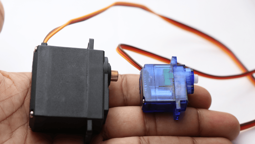
A servo motor is a type of motor that rotates to a specific angle and holds that position. Unlike a regular DC motor that just spins continuously, a servo uses a closed-loop feedback system to achieve precise angle control. Because of this, servos are the go-to choice for applications where exact positioning matters, like robotic arms, steering mechanisms, and camera gimbals.
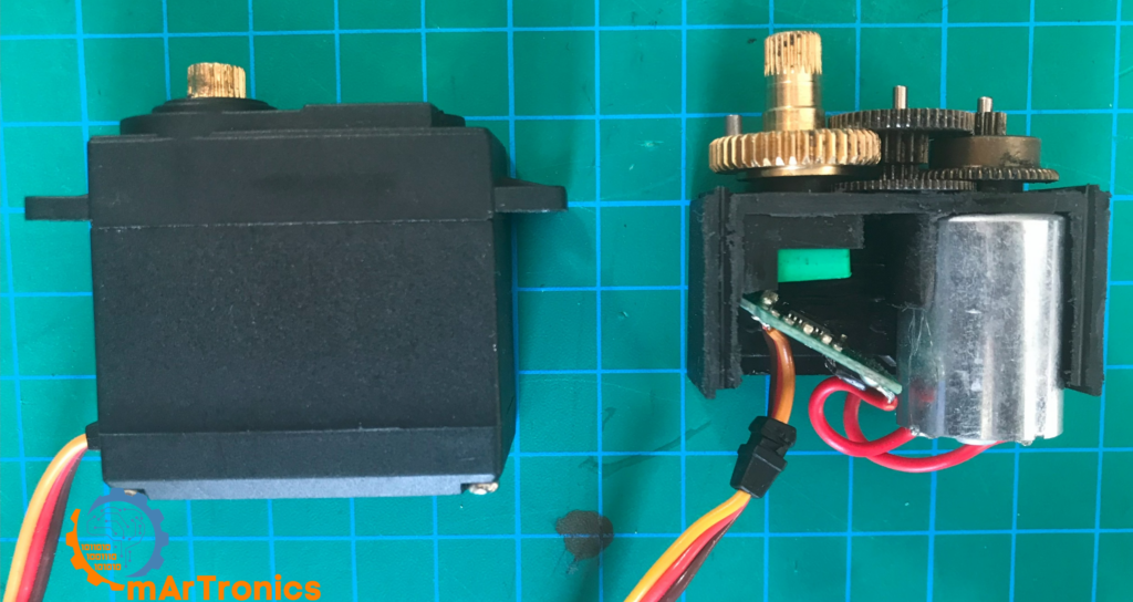
Internal components of a servo motor
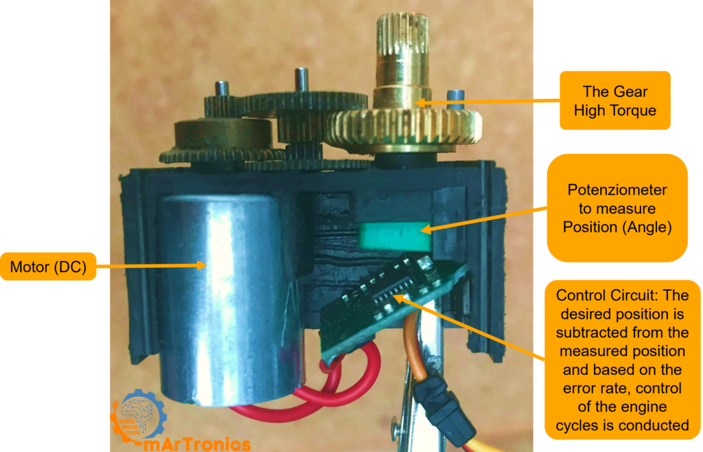
If you open up a typical hobby servo, you will find four main components working together inside:
- محرك التيار المستمر: First, this is the core actuator that converts electrical energy into rotational motion. It provides the raw spinning force.
- سلسلة التروس: Next, a set of reduction gears (plastic in the SG90, metal in the MG996R) that reduces the motor’s high RPM down to a slower, higher-torque output at the shaft.
- مقياس الجهد: Then, a small variable resistor connected to the output shaft. It continuously reports the shaft’s current angle back to the control circuit.
- دائرة التحكم: Finally, a small PCB inside the servo that compares the desired position (from the PWM signal) with the actual position (from the potentiometer) and drives the motor to close the gap.
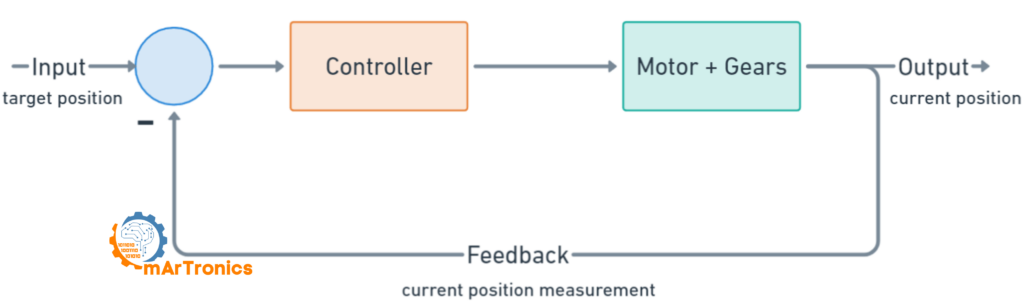
Closed-loop control: how the servo knows where to go
Every servo relies on التحكم ذو الحلقة المغلقة. In short, here is how it works step by step:
- First, the Arduino sends a PWM signal that encodes the desired angle.
- Then, the servo’s control circuit reads the pulse width and calculates the target position.
- Next, the control circuit reads the potentiometer to determine the shaft’s current position.
- After that, if there is a difference between the target and the current position, the circuit drives the DC motor in the correct direction.
- Finally, once the potentiometer reading matches the target, the motor stops and holds position.
As a result, the servo continuously corrects itself, holding the exact angle even under external load. This feedback loop is what makes servos so dependable in robotics.
Servo PWM signal explained: how pulse width controls angle
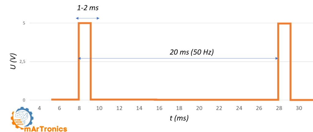
Pulse Width Modulation (PWM) is how your Arduino talks to a servo motor. Instead of sending a voltage level, the Arduino sends a series of digital pulses at a fixed frequency. In essence, the width of each pulse tells the servo which angle to move to.
For standard hobby servos, the PWM signal runs at 50 هرتز, meaning one pulse goes out every 20 milliseconds. Within each 20 ms window, only the HIGH portion (the pulse width) matters. Typically, a pulse width between 1.0 ms and 2.0 ms maps to the full range of servo motion from 0 to 180 degrees.
PWM pulse width vs servo position table
The table below shows how different pulse widths map to specific servo positions. Keep in mind that exact values can vary a bit depending on the servo model:
| عرض النبضة (مللي ثانية) | وضع المؤازرة | دورة التشغيل عند 50 هرتز |
|---|---|---|
| 0.5 مللي ثانية | 0° (الحد الأدنى، بعض المحركات المؤازرة) | 2.5% |
| 1.0 مللي ثانية | 0° (الحد الأدنى القياسي) | 5% |
| 1.25 مللي ثانية | 45 درجة | 6.25% |
| 1.5 مللي ثانية | 90 درجة (الوضع المركزي) | 7.5% |
| 1.75 مللي ثانية | 135 درجة | 8.75% |
| 2.0 مللي ثانية | 180 درجة (الحد الأقصى القياسي) | 10% |
| 2.5 مللي ثانية | 180 درجة (كحد أقصى، بعض المحركات المؤازرة) | 12.5% |
The Arduino Servo library handles most of this for you automatically. For example, when you call servo.write(90), the library generates a 1.5 ms pulse at 50 Hz to move the servo to center position. Still, understanding the underlying PWM signal helps a lot when troubleshooting jitter, calibrating custom ranges, or working with the PCA9685 driver.
SG90 vs MG996R: choosing the right servo for your project
ال محرك سيرفو صغير SG90 و محرك سيرفو قياسي MG996R are the two most popular hobby servos in Arduino projects. Which one you pick depends on your project’s torque, size, and durability needs. Below is a side-by-side comparison:

| مواصفة | محرك سيرفو صغير SG90 | محرك سيرفو MG996R |
|---|---|---|
| عزم الدوران عند التوقف | 1.2 كجم·سم عند 4.8 فولت، 1.6 كجم·سم عند 6 فولت | 11 كجم·سم عند 4.8 فولت، 13 كجم·سم عند 6 فولت |
| جهد التشغيل | من 3.5 إلى 6 فولت | من 4.8 إلى 7.2 فولت |
| تيار اللاحمل | 100 مللي أمبير | 220 مللي أمبير عند 4.8 فولت، 250 مللي أمبير عند 6 فولت |
| تيار التوقف | 650 مللي أمبير | 900 مللي أمبير عند 4.8 فولت، 1400 مللي أمبير عند 6 فولت |
| سرعة التشغيل | 0.12 ثانية لكل 60 درجة عند 4.8 فولت | 0.15 ثانية لكل 60 درجة عند 4.8 فولت |
| وزن | 9 غرام | 55 غرام |
| نوع التروس | تروس بلاستيكية | تروس معدنية |
| نطاق الدوران | 180 درجة | 180 درجة |
| حالة الاستخدام المثالية | مشاريع خفيفة الوزن، روبوتات صغيرة قابلة للتحريك والإمالة | أذرع آلية، مفاصل عالية التحمل، مركبات يتم التحكم فيها عن بعد |
| الإيجابيات | رخيص، خفيف الوزن، استهلاك منخفض للطاقة | عزم دوران عالٍ، تروس معدنية متينة، دقة عالية |
| السلبيات | عزم الدوران المنخفض، والتروس البلاستيكية قد تتلف | أثقل وزناً، ويستهلك تياراً أعلى، وأكثر تكلفة |
So in short, go with the SG90 when weight and space are limited and loads are light. Pick the MG996R when you need real torque, for example in a مشروع ذراع روبوتية بست درجات حرية where the shoulder and elbow joints carry heavy loads. A lot of robotic arm builds, including ours, use a mix of both: MG996R for the heavy base joints and SG90 for the lighter wrist and gripper.
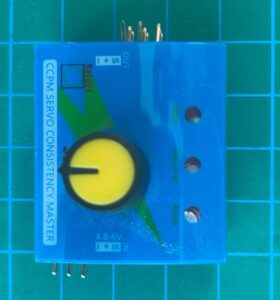
Servo testers: a useful calibration tool
Before you wire a servo to your Arduino, a جهاز اختبار المؤازرة is a handy standalone tool for quickly checking that a servo works. In particular, these cheap modules (usually just a few dollars) let you sweep through the full range or dial in specific positions with a knob, without any code or microcontroller. They are especially useful when calibrating multiple servos for a robotics build.
Powering servos safely: current draw and external supplies
One of the most common mistakes beginners make is powering servos directly from the Arduino’s 5 V pin. Although this might work for a single SG90 under light load, it is not a good idea for most projects. Here is why, and what to do instead.
Why not power servos from the Arduino 5 V pin?
The Arduino Uno’s 5 V regulator can only supply about 500 mA total. However, a single SG90 servo can pull up to 650 mA at stall, and an MG996R can hit 1400 mA. Therefore, if the servo demands more current than the regulator can deliver, you will see voltage drops that cause the Arduino to reset or act unpredictably.
External power supply recommendations
To power servos reliably, use a dedicated external power supply rated at 5 V to 6 V with enough current. For instance, a 5 V 2 A adapter works well for one or two SG90 servos, while a 5 V 10 A power supply is better for projects with six or more servos, like a robotic arm.
Always follow these wiring rules for Arduino servo motor control:
- أرضية مشتركة: First, connect the ground of the external power supply to the Arduino GND. Without a common ground, the PWM signal has no reference and the servo will not respond.
- قضبان طاقة منفصلة: Next, connect the servo’s red (power) wire to the external supply’s positive terminal, not to the Arduino 5 V pin.
- سلك الإشارة فقط: Also, the only connection between the Arduino and the servo should be the signal (PWM) wire.
- مكثفات الفصل: Finally, place a 100 uF electrolytic capacitor across the power rails near the servos to reduce voltage spikes and jitter.
Current draw quick reference
| نموذج سيرفو | تيار اللاحمل | تيار التوقف | الكمية الموصى بها لكل محرك سيرفو |
|---|---|---|---|
| SG90 | 100 مللي أمبير | 650 مللي أمبير | 5 فولت، 1 أمبير على الأقل |
| MG996R | 220 مللي أمبير | 1400 مللي أمبير | 6 فولت، 2 أمبير على الأقل |
For example, a project with six servos running at once can easily exceed 3 A peak current. That is why a solid external power supply matters so much for any serious Arduino servo project.
Servo motor wiring: understanding the three wires
Before connecting your servo to an Arduino, you first need to understand the three-wire connector that all standard hobby servos use:
| دبوس | إشارة | لون السلك |
|---|---|---|
| 1 | أرضي (GND) | أسود أو بني |
| 2 | الطاقة (VCC، من 4.8 إلى 6 فولت) | أحمر |
| 3 | إشارة التحكم (PWM) | برتقالي أو أصفر |
Most servos follow this same pinout regardless of manufacturer. Specifically, the ground wire is always on one edge, power in the middle, and signal on the other edge. If you are ever unsure, just double-check the datasheet for your servo model.
Project 1: Arduino servo sweep – your first servo project
يُعد رسم "الكنس" مشروعًا كلاسيكيًا للمبتدئين في التحكم في محرك سيرفو باستخدام أردوينو. Basically, it makes the servo rotate back and forth between 0 and 180 degrees continuously. As a result, this project teaches you the basics of the Arduino Servo library and also confirms that your wiring is correct.
Parts needed for the sweep project
- أردوينو أونو (أو أي لوحة أردوينو أخرى)
- محرك سيرفو صغير SG90 (أو ما شابه)
- مصدر طاقة خارجي 5 فولت للمحرك المؤازر (موصى به)
- لوحة تجارب وأسلاك توصيل
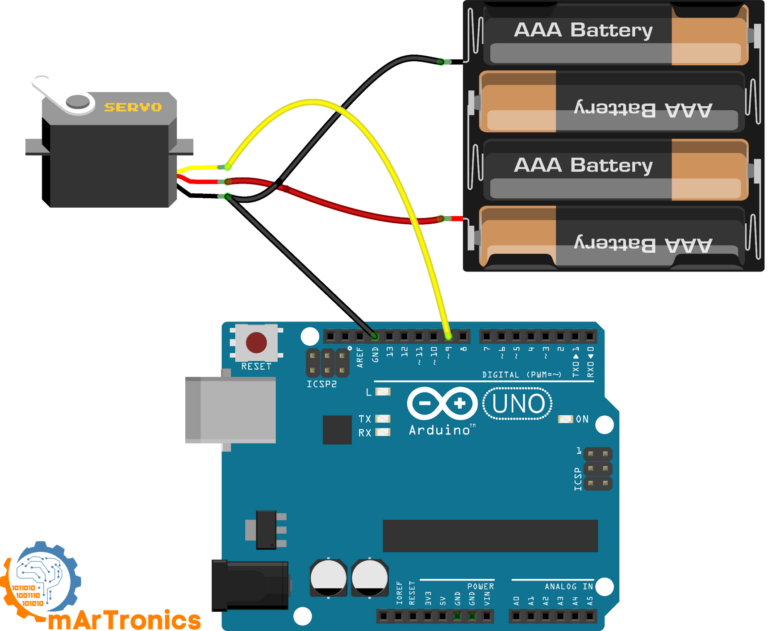
Sweep wiring connections
| سلك المؤازرة | يتصل بـ |
|---|---|
| بني أو أسود (GND) | أرضي أردوينو وأرضي مصدر الطاقة الخارجي |
| أحمر (VCC) | مصدر طاقة خارجي 5 فولت موجب |
| برتقالي أو أصفر (إشارة) | المنفذ الرقمي 9 في أردوينو |
Sweep Arduino code
To get started, open the Arduino IDE and go to ملف، أمثلة، سيرفو، مسح, or just copy the code below. The Sweep example comes built into the standard Arduino Servo library.
/* Sweep من تصميم BARRAGAN http://barraganstudio.com هذا الكود متاح للاستخدام العام. تم تعديله في 8 نوفمبر 2013 بواسطة سكوت فيتزجيرالد https://www.arduino.cc/en/Tutorial/LibraryExamples/Sweep */ #include Servo myservo; // إنشاء كائن سيرفو للتحكم في سيرفو // يمكن إنشاء اثني عشر كائن سيرفو على معظم اللوحات int pos = 0; // متغير لتخزين موضع السيرفو void setup() { myservo.attach(9); // يربط السيرفو بالمنفذ 9 بكائن السيرفو } void loop() { for (pos = 0; pos <= 180; pos += 1) { // ينتقل من 0 درجة إلى 180 درجة // بخطوات 1 درجة myservo.write(pos); // يخبر السيرفو بالانتقال إلى الموضع في المتغير 'pos' delay(15); // ينتظر 15 مللي ثانية حتى يصل السيرفو إلى الموضع } for (pos = 180; pos >= 0; pos -= 1) { // ينتقل من 180 درجة إلى 0 درجة myservo.write(pos); // يخبر السيرفو بالانتقال إلى الموضع في المتغير 'pos' delay(15); // ينتظر 15 مللي ثانية حتى يصل المحرك المؤازر إلى الموضع المطلوب } }
How the sweep code works line by line
Although the Sweep sketch is short, it covers all the core concepts for محرك سيرفو بتقنية تعديل عرض النبضة (PWM) مع أردوينو يتحكم:
#include <Servo.h>– First, this line imports the Arduino Servo library, which handles all the PWM timing for you.سيرفو ماي سيرفو؛;– هذا يُنشئ كائن سيرفو. يمكنك إنشاء ما يصل إلى 12 كائن سيرفو على لوحة أردوينو أونو.myservo.attach(9);– Then, this tells the library to send PWM signals on digital pin 9.myservo.write(pos);– يقوم هذا الأمر بتحريك المحرك المؤازر إلى الزاوية المخزنة في المتغيرنقاط البيع. تتراوح القيمة من 0 إلى 180.- Finally, the two
لتقوم الحلقات بمسح الزاوية من 0 إلى 180 ثم العودة من 180 إلى 0، مع تأخير 15 مللي ثانية بين كل خطوة للحصول على حركة سلسة.
If the servo moves in the wrong direction or does not reach the full range, try adjusting the delay or check your power supply. Similarly, if you notice jitter at the endpoints, that usually means the servo cannot physically reach those extreme angles.
Project 2: Controlling a servo with a potentiometer (Knob)
مشروع ذا نوب يأخذ التحكم في محرك سيرفو باستخدام أردوينو a step further by adding a potentiometer as an input device. Basically, turning the knob directly controls the servo angle in real time. In this project you will learn how to read analog inputs and map them to servo positions, which is a pattern you will use in all sorts of robotics projects.
Parts needed for the Knob project
- أردوينو أونو (أو أي لوحة أردوينو أخرى)
- محرك سيرفو صغير SG90 (أو ما شابه)
- مقياس جهد 10 كيلو أوم
- مصدر طاقة خارجي 5 فولت للمحرك المؤازر (موصى به)
- لوحة تجارب وأسلاك توصيل
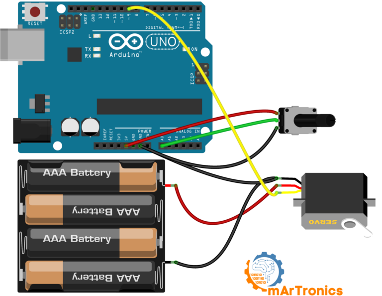
Knob wiring connections
| عنصر | دبوس أو سلك | يتصل بـ |
|---|---|---|
| أرضي المؤازرة (بني/أسود) | أرضي | أرضي أردوينو وأرضي مصدر الطاقة الخارجي |
| سيرفو VCC (أحمر) | VCC | مصدر طاقة خارجي 5 فولت موجب |
| إشارة المؤازرة (برتقالي/أصفر) | إشارة | المنفذ الرقمي 9 في أردوينو |
| دبوس مقياس الجهد 1 | الدبوس الخارجي | أردوينو 5 فولت |
| ماسحة مقياس الجهد | الدبوس الأوسط | منفذ التناظري A0 في أردوينو |
| دبوس مقياس الجهد 3 | الدبوس الخارجي | أرضي أردوينو |
Knob Arduino code
Next, open the Arduino IDE and go to ملف، أمثلة، محرك سيرفو، مقبض, أو استخدم الرمز أدناه:
/* التحكم في موضع محرك سيرفو باستخدام مقياس جهد (مقاومة متغيرة) بواسطة ميخال رينوت http://people.interaction-ivrea.it/m.rinott تم تعديله في 8 نوفمبر 2013 بواسطة سكوت فيتزجيرالد http://www.arduino.cc/en/Tutorial/Knob */ #include Servo myservo; // إنشاء كائن سيرفو للتحكم في سيرفو int potpin = A0; // منفذ تناظري يُستخدم لتوصيل مقياس الجهد int val; // متغير لقراءة القيمة من المنفذ التناظري void setup() { myservo.attach(9); // توصيل السيرفو بالمنفذ 9 لكائن السيرفو } void loop() { val = analogRead(potpin); // قراءة قيمة مقياس الجهد (قيمة بين 0 و1023) val = map(val, 0, 1023, 0, 180); // تحويل القيمة لاستخدامها مع السيرفو (قيمة بين 0 و180) myservo.write(val); // ضبط موضع السيرفو وفقًا للقيمة المُحوّلة delay(15); // انتظار وصول السيرفو إلى الموضع المطلوب }
How the Knob code works: analogRead and map
Essentially, the two key functions in this sketch are analogRead() و رسم خريطة():
analogRead(A0)– First, this reads the potentiometer voltage and returns a value between 0 and 1023 (10-bit ADC resolution).map(val, 0, 1023, 0, 180)– Then, this converts the 0 to 1023 range to a 0 to 180 degree range for the servo.myservo.write(val)– Finally, this sends the mapped angle to the servo.
إذا كنت ترغب في تحكم أدق في موضع المحرك المؤازر، يمكنك استخدام myservo.writeMicroseconds() بدلاً من myservo.write(). This lets you set the pulse width directly in microseconds (for example, 1000 to 2000), which gives you much higher resolution than the 0 to 180 degree range. Also, if the servo does not reach the full range when you turn the potentiometer all the way, try adjusting the map values slightly, for example map(val, 0, 1023, 10, 170).
PCA9685 servo driver: control up to 16 servos with Arduino
Controlling one or two servos directly from Arduino pins works fine, but what happens when you need more? The Arduino Uno only has six PWM-capable pins, and each servo uses one. On top of that, running more than a couple of servos can cause timing conflicts and jitter. This is where the محرك سيرفو PCA9685 comes in.
What is the PCA9685 and why use it?
شريحة PCA9685 هي شريحة تحكم PWM ذات 16 قناة و12 بت، تتواصل مع أردوينو عبر ناقل I2C. Instead of using Arduino PWM pins, the PCA9685 generates all 16 PWM signals on its own. As a result, you free up Arduino pins for sensors and other tasks, and the dedicated hardware PWM gives you rock-steady signals with zero jitter.
Furthermore, you can daisy-chain up to 62 PCA9685 boards on a single I2C bus, which in theory gives you 992 servo channels. In practice though, a single board with 16 channels is more than enough for most projects.
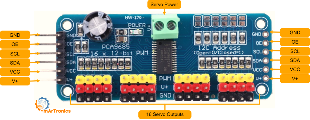
PCA9685 board connections explained
The PCA9685 breakout board has these main connections:
- VCC: مصدر الطاقة المنطقية (3.3 فولت أو 5 فولت من أردوينو). هذا المصدر يُشغّل شريحة PCA9685 فقط، وليس المحركات المؤازرة.
- أرضي: يجب أن يكون التأريض مشتركًا مع أردوينو ومصدر طاقة المحرك المؤازر.
- SDA: خط بيانات I2C. قم بالتوصيل بمنفذ A4 (أونو) في أردوينو أو بمنفذ SDA.
- SCL: خط ساعة I2C. قم بالتوصيل بمنفذ A5 (أونو) في أردوينو أو بمنفذ SCL.
- V+: مدخل طاقة المحرك المؤازر. قم بتوصيل مصدر طاقة خارجي بجهد يتراوح بين 5 و 6 فولت هنا. هذا يُشغّل جميع قنوات المحرك المؤازر الـ 16.
- OE: تفعيل الإخراج. اتركه غير موصول (موصولاً بالأرض داخلياً) للحفاظ على جميع المخارج نشطة.
When to use PCA9685 instead of direct Arduino control
In short, use the PCA9685 when you need to التحكم في عدة محركات سيرفو باستخدام أردوينو (more than two or three), when you want jitter-free motion, or when your project needs those Arduino PWM pins for other things like LED dimming or motor speed control. For simple one-servo projects, direct Arduino control works just fine.
Project 3: Dual servo control with PCA9685 and potentiometers
This project shows how to control two servos independently using a PCA9685 driver board and two potentiometers. In other words, it brings together everything you have learned about analog input, servo PWM, and I2C communication into one practical build.
Parts needed for the PCA9685 dual servo project
| عنصر | كمية |
|---|---|
| أردوينو أونو | 1 |
| لوحة تشغيل محرك سيرفو PCA9685 | 1 |
| محرك سيرفو صغير SG90 (أو ما شابه) | 2 |
| مقياس جهد 10 كيلو أوم | 2 |
| مصدر طاقة خارجي 5 فولت أو 6 فولت (2 أمبير على الأقل) | 1 |
| لوحة تجارب وأسلاك توصيل | حسب الحاجة |
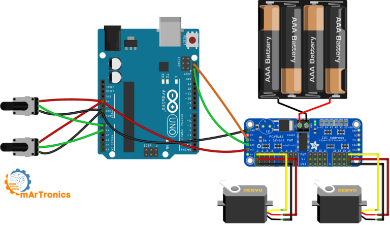
PCA9685 dual servo wiring
| اتصال | من | ل |
|---|---|---|
| بيانات I2C | أردوينو A4 (SDA) | PCA9685 SDA |
| ساعة I2C | أردوينو A5 (SCL) | PCA9685 SCL |
| قوة المنطق | أردوينو 5 فولت | PCA9685 VCC |
| أرضية مشتركة | أرضي أردوينو | أرضي PCA9685 وأرضي مصدر الطاقة الخارجي |
| طاقة المؤازرة | مصدر طاقة خارجي 5 فولت موجب | طرف V+ لـ PCA9685 |
| سيرفو 1 | موصل ثلاثي الأطراف | قناة PCA9685 0 |
| سيرفو 2 | موصل ثلاثي الأطراف | القناة 15 من PCA9685 |
| منزلق مقياس الجهد 1 | الدبوس الأوسط | أردوينو A0 |
| مقياس الجهد 2 ماسحة | الدبوس الأوسط | أردوينو A1 |
| الأطراف الخارجية لمقياس الجهد | الدبابيس الخارجية | أردوينو 5 فولت و GND |
PCA9685 dual servo Arduino code
For this sketch, you need the Adafruit PWM Servo Driver library. You can install it from the Arduino Library Manager by searching for “Adafruit PWM Servo Driver”. The code reads both potentiometers and maps their values to servo pulse widths:
/** * المؤلف: عمر درايدريا * التاريخ: 2024/05/07 * يتحكم هذا الكود في محركات المؤازرة باستخدام مشغل PWM من نوع PCA9685 ومقاييس الجهد. */ #include #include // تهيئة وحدة PCA9685 باستخدام العنوان الافتراضي (0x40). Adafruit_PWMServoDriver pwm = Adafruit_PWMServoDriver(); void setup() { Serial.begin(9600); // بدء الاتصال التسلسلي لأغراض التصحيح. pwm.begin(); // تهيئة وحدة PCA9685. // ضبط التردد على 60 هرتز، وهو مناسب للتحكم في المحرك المؤازر. pwm.setPWMFreq(60); // إعداد المنافذ التناظرية كمدخلات. pinMode(A0, INPUT); pinMode(A1, INPUT); } void loop() { // قراءة قيم المقاومات المتغيرة. int potVal0 = analogRead(A0); // قراءة قيمة المقاومة المتغيرة الأولى. int potVal1 = analogRead(A1); // قراءة قيمة المقاومة المتغيرة الثانية. // ربط قيم المقاومات المتغيرة بأطوال نبضات المحرك المؤازر. int servoPos0 = map(potVal0, 0, 1023, 150, 600); // غيّر القيم من 150 إلى 600 حسب مواصفات المحرك المؤازر. int servoPos1 = map(potVal1, 0, 1023, 150, 600); // اضبط مواضع المحرك المؤازر. pwm.setPWM(0, 0, servoPos0); // اضبط المحرك المؤازر على القناة 0. pwm.setPWM(15, 0, servoPos1); // اضبط المحرك المؤازر على القناة 15. delay(20); // تأخير بسيط لتقليل الارتعاش. }
Understanding the PCA9685 pulse range values
في الكود أعلاه، ستلاحظ تمرير قيم مثل 150 و 600 إلى setPWM(). These are not degrees or milliseconds. Instead, they are 12-bit PWM counts out of 4096 total ticks per cycle. For instance, a value of 150 is roughly 0.73 ms pulse width, and 600 is roughly 2.93 ms. For most standard servos, a range of من 150 إلى 600 covers the full 0 to 180 degree rotation. That said, you may need to tweak these values for your specific servo to avoid end-stop buzzing.
To test the setup, upload the code and then slowly turn each potentiometer. Make sure each servo responds independently. If a servo does not move, double-check the I2C connections and confirm that the external power supply is connected to V+ on the PCA9685 board.
Troubleshooting common Arduino servo problems
Even experienced makers run into servo issues now and then. Below are the most common problems and their solutions.
Servo jitter or twitching
If your servo vibrates or twitches instead of holding a steady position, the most likely cause is an unstable power supply. When the servo draws current spikes, the supply voltage drops momentarily, and as a result the control circuit loses its reference. To fix this, use a dedicated external power supply with adequate current and add a 100 uF to 470 uF electrolytic capacitor across the servo power rails. In addition, noisy PWM signals from software-based servo control can also cause jitter, which is another good reason to consider the PCA9685 hardware PWM driver.
Servo not moving at all
If the servo does not respond to commands, first check these things: verify that the signal wire is connected to the correct PWM-capable Arduino pin, confirm that the ground is shared between the Arduino and the servo power supply, and make sure the power supply is actually on and delivering the correct voltage. Also, check that the Servo library is included and the servo is properly attached in your code with servo.attach(pin).
Servo overheating
Servo overheating usually happens when the motor is stalled, meaning it is trying to hold a position against a load that exceeds its torque rating. In this state, the motor continuously draws stall current, which consequently generates a lot of heat. To prevent this, either reduce the mechanical load, use a higher-torque servo, or add rest periods in your code by detaching the servo when it does not need to hold position. For example, calling servo.detach() stops the PWM signal and lets the motor relax.
Noisy power supply and voltage brownouts
When multiple servos move at the same time, the combined current draw can cause voltage sags on a weak power supply. As a result, the Arduino may reset, LEDs may flicker, or servos may move erratically. Therefore, use a power supply with a higher current rating and add bulk capacitance (at least 470 uF) near the servos. Besides that, keep the power supply wires as short and thick as possible to minimize voltage drop.
Wrong pulse range or limited rotation
If your servo does not reach the full 0 to 180 degree range, the problem is likely the pulse width limits in your code. Because different servo models can have slightly different pulse ranges, you may need to adjust them. For direct Arduino control, you can specify custom limits with servo.attach (دبوس، minPulse، maxPulse), ، على سبيل المثال servo.attach(9, 544, 2400). Similarly, for the PCA9685, adjust the minimum and maximum PWM count values (for instance, 125 to 625 instead of 150 to 600).
Wrong ground wiring
Without a common ground between the Arduino and the servo power supply, the PWM signal has no valid reference voltage. Consequently, the servo may ignore commands entirely or behave unpredictably. So always connect all ground wires together, whether you are using a single power source or separate supplies for logic and servos.
Frequently asked questions (FAQ)
كم عدد المحركات المؤازرة التي يمكنني التحكم بها باستخدام لوحة أردوينو أونو واحدة؟
With the standard Servo library, you can control up to 12 servos on an Arduino Uno. However, each servo uses a timer, so running many servos may interfere with PWM on certain pins. If you need more, a PCA9685 board adds 16 channels with no timer conflicts.
هل يمكنني استخدام محرك سيرفو بدون مكتبة برمجية؟
Yes, you can technically do it with digitalWrite() and delayMicroseconds(). But this approach is less precise and blocks the CPU. Because the Servo library handles timing automatically, there is no good reason to do it manually.
ما الفرق بين servo.write() و servo.writeMicroseconds()؟
The servo.write() function takes a degree angle (0 to 180) and converts it to a pulse width. In contrast, servo.writeMicroseconds() lets you set the exact pulse width (typically 1000 to 2000 us), so you get finer control over position.
لماذا يصدر محرك السيرفو الخاص بي صوت طنين أو اهتزاز في أوضاع معينة؟
This usually means the servo is near its mechanical limit or the signal is slightly unstable. As a result, the control loop keeps trying to correct a tiny position error. To fix it, adjust your pulse range to avoid extremes and use a stable power supply.
هل يمكنني تشغيل محرك سيرفو ببطارية 9 فولت؟
A 9 V battery is not a good choice for servos. Most hobby servos need 4.8 to 6 V, and besides that, 9 V batteries have very limited current capacity (around 500 mAh). Use a proper 5 V supply instead.
ماذا يرمز إليه PCA9685؟
PCA9685 is an NXP Semiconductors part number for a 16-channel, 12-bit PWM controller IC with I2C interface. In the maker community, it is mainly used as a servo driver, although it can also control LEDs and other PWM devices.
هل يمكنني استخدام محركات MG996R و SG90 معًا في نفس المشروع؟
Yes, and in fact many robotic arm builds do exactly that. They use MG996R servos for the high-torque base and shoulder joints, and SG90 servos for the lighter wrist and gripper. Just make sure your power supply handles the combined current.
كيف يمكنني التحكم في محرك سيرفو ذي دوران مستمر باستخدام أردوينو؟
Continuous rotation servos work differently because the pulse width controls speed and direction instead of angle. A 1.5 ms pulse stops the motor, shorter pulses spin it one way, and longer pulses spin it the other way. You can still use the Servo library: servo.write(90) stops, servo.write(0) is full speed one way, servo.write(180) is full speed the other.
لماذا تتم إعادة ضبط جهاز أردوينو الخاص بي عندما يتحرك المحرك المؤازر؟
This happens because the servo draws too much current, causing a voltage drop that resets the Arduino. The fix is simple: power the servo from a separate external supply and share only the ground with the Arduino.
هل يمكنني التحكم في محرك سيرفو عبر البلوتوث باستخدام أردوينو؟
Yes. By adding an HC-05 or HC-06 Bluetooth module, you can send servo angle commands wirelessly from a phone or computer. The Arduino receives them over serial and moves the servo. For a full walkthrough, check our HC-05 Bluetooth module guide.
Resources, libraries, and downloads
Below is a quick reference of all the tools, libraries, and files you need for the projects in this tutorial:
Arduino libraries used
- Servo.h – مُدمج في بيئة تطوير أردوينو المتكاملة. لا حاجة للتثبيت. يُستخدم في المشروع 1 (المسح) والمشروع 2 (المقبض).
- محرك سيرفو PWM من Adafruit - قم بالتثبيت من مدير مكتبة أردوينو. ابحث عن "Adafruit PWM Servo Driver". يُستخدم في المشروع 3 (PCA9685 Dual Servo).
- Wire.h – مُدمج في بيئة تطوير Arduino المتكاملة. مطلوب للاتصال عبر بروتوكول I2C مع PCA9685.
Code download and wiring diagrams
جميع رموز المشاريع الثلاثة مضمنة مباشرةً في هذه المقالة أعلاه. يمكنك أيضًا العثور على ملفات المصدر ومخططات الأسلاك على موقعنا الإلكتروني. مستودع GitHub. In addition, every wiring diagram in this tutorial is available as a high-resolution image, so just right-click and save.
Recommended next tutorials on OmArTronics
Once you feel comfortable with basic Arduino servo control, here are some more advanced projects worth exploring next:
- بناء ذراع روبوتية بست درجات حرية بنفسك – قم ببناء ذراع روبوتية كاملة باستخدام ستة محركات مؤازرة يتم التحكم فيها بواسطة مقاييس الجهد.
- ذراع روبوتية يتم التحكم بها بتقنية البلوتوث – أضف تحكمًا لاسلكيًا عبر البلوتوث إلى ذراعك الروبوتية باستخدام وحدة HC-05 وتطبيق Android مخصص.
- نظام تحكم مؤازر مع عصا تحكم وشاشة OLED – التحكم في المحركات المؤازرة باستخدام عصا التحكم مع عرض معلومات الموقع في الوقت الفعلي على شاشة OLED.
- ذراع الروبوت المتحرك (OmObiArm) – دمج ذراع روبوتية مع قاعدة مركبة جوالة متنقلة للحصول على منصة معالجة متنقلة بالكامل.
- شرح كامل لوحدة بلوتوث HC-05 – تعلم كل شيء عن الاتصال التسلسلي بتقنية البلوتوث مع أردوينو.
خاتمة
In this tutorial, you learned how servo motors work on the inside: the DC motor, gear train, potentiometer feedback, and closed-loop control system. You also now understand how PWM signals at 50 Hz translate pulse width into precise angular position. And finally, you have completed three practical projects: the Sweep sketch for basic motion, the Knob project for analog input control, and the PCA9685 dual servo project for scaling up to multiple servos.
Along the way, you also learned how to choose between the SG90 and MG996R servos, how to power servos safely with external supplies, and how to troubleshoot common issues like jitter, brownouts, and overheating. In summary, these skills come up in just about every robotics project.
So what is your next step? Put what you have learned into a real project. For instance, building a ذراع روبوتية يمكنك صنعها بنفسك is one of the best ways to solidify your servo control skills, and our step-by-step guide will walk you through the entire build.
3 رأي حول “Arduino Servo Control Guide: SG90, PWM, and PCA9685”