
Quick Summary
This tutorial shows you how to build a PID-controlled line-following robot using an Arduino Uno, TCS34725 RGB color sensor, and Arduino Motor Shield Rev3. The robot uses automatic calibration to detect track contrast and applies proportional-integral-derivative control for smooth, stable line tracking. Includes complete 3D-printed chassis design, wiring diagrams, full Arduino code, and PID tuning instructions.
In this tutorial, you will build a TCS34725 line-following robot that uses an RGB color sensor and a PID controller to navigate tracks with precision and stability. If you completed the beginner line-following robot with KY-033 IR sensors, this project picks up right where that one left off. You will replace the simple infrared sensor with the TCS34725 RGB light sensor, add a full PID control loop, and as a result get noticeably smoother line tracking, even on tighter curves.
This tutorial covers the complete build process: 3D-printed chassis design, wiring, calibration, Arduino programming, and PID tuning. So whether you are building your first Arduino PID line follower or upgrading from a simpler design, this guide walks you through everything from hardware assembly to code and tuning for an advanced line-following robot powered by the TCS34725 sensor and the Arduino Motor Shield Rev3.
What you will learn
- How the TCS34725 RGB sensor detects the contrast between the track line and the background surface
- How PID control improves line-following stability compared to simple on/off steering
- How the Arduino Uno and Motor Shield Rev3 work together to drive the robot
- How the robot calibrates itself automatically by sampling black and white areas
- How to wire, assemble, program, and test the complete robot
- How to tune PID parameters (Kp, Ki, Kd) for better performance on different tracks
How the robot works
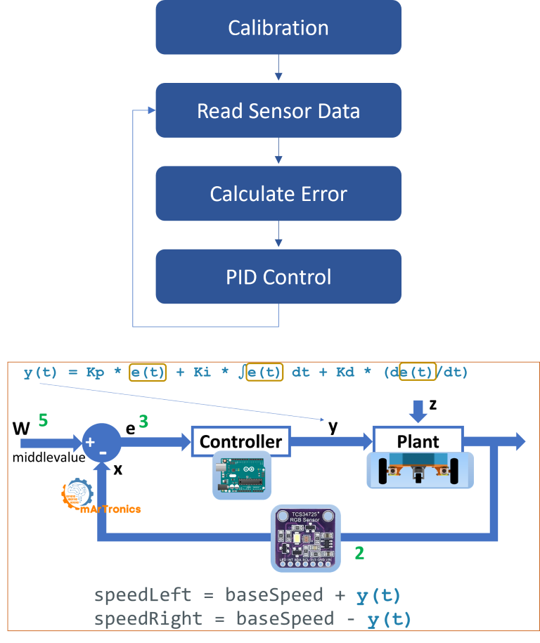
Before getting into the build, here is a quick overview of how the system works. This TCS34725 Arduino robot uses a closed-loop feedback system, so sensor input directly controls motor output through a PID algorithm. Here is what each component does:
The Arduino Uno is the brain of the robot. It reads sensor data, runs the PID calculations, and sends speed commands to both motors. On top of that, the Arduino Motor Shield Rev3 sits on top of the Uno and handles power distribution and direction control for the two DC motors. It lets the Arduino independently control the speed and direction of each wheel, which is how the robot steers.
Sensor and calibration
Mounted on the underside of the robot, the TCS34725 RGB light sensor faces down toward the track surface. Unlike a simple IR reflectance sensor that only sees light or dark, the TCS34725 measures light intensity across red, green, blue, and clear channels. For this project, though, the clear channel (C) is the one that matters because it gives a reliable overall brightness reading that cleanly separates a dark line from a light background.
During startup, the robot runs an automatic calibration routine. It rotates slightly to position the sensor over a dark area, records the light intensity as the black value, and then rotates the other way to sample the white background. The average of these two readings becomes the threshold (middleValue). Once calibration is done, the sensor continuously reads the clear channel while the robot moves, and the difference between the current reading and the threshold becomes the error signal that feeds into the PID controller.
From there, the PID controller takes this error and calculates a correction value. A positive correction means the robot needs to steer one way; a negative correction means the opposite. This correction is added to the left motor speed and subtracted from the right motor speed (or vice versa), which creates smooth differential steering. So the robot follows the line with minimal oscillation and also handles curves well, a big improvement over the simpler bang-bang control used in the KY-033 line-following robot tutorial.
Components needed (bill of materials)
The table below lists every component you need for this RGB sensor line-following robot. If you already built the KY-033 line-following robot, you can reuse the chassis, motors, wheels, Arduino, and motor shield. The only new part is the TCS34725 sensor module.
3D-printed parts
These parts are custom-designed for this project and can be downloaded as STL files from Cults3D or get the complete project package from our OmArTronics Shop.
| Component | Required / Optional | Purpose | Notes |
|---|---|---|---|
| Chassis | Required | Houses the motors, sensor, and Arduino board | 3D-printed, PLA or ABS recommended |
| Sensor Holder | Required | Aligns the TCS34725 sensor for consistent line detection | Keeps sensor at correct height above the track |
| Arduino Holder | Required | Mounts the Arduino Uno securely to the chassis | Provides easy access for programming and wiring |
Motors, wheels, and electronics
| Component | Qty | Required / Optional | Purpose | Notes |
|---|---|---|---|---|
| DC Motor with Gearbox | 2 | Required | Drives the robot wheels | Standard yellow TT motors work well |
| Wheels | 2 | Required | Provide mobility | Must fit the motor shafts |
| Support Wheel (Caster) | 1 | Required | Balances the robot at the rear | Ball caster or swivel caster |
| Arduino Uno | 1 | Required | Microcontroller for programming and control | Runs PID calculations and reads sensor data |
| Arduino Motor Shield Rev3 | 1 | Required | Drives both motors and distributes power | Stacks directly on the Arduino Uno |
| TCS34725 RGB Light Sensor | 1 | Required | Measures light intensity to detect line contrast | Uses the clear (C) channel for this project |
| Jumper Wires | Several | Required | Connects components | M/F and M/M pin headers |
| Screws and Threaded Inserts | As needed | Required | Securely mounts all parts to the chassis | M3 screws recommended |
| Battery (7.4V LiPo or 9V) | 1 | Required | Powers the robot | LiPo recommended for consistent voltage |
| Power Switch | 1 | Optional | Easy on/off control | Saves battery life between tests |
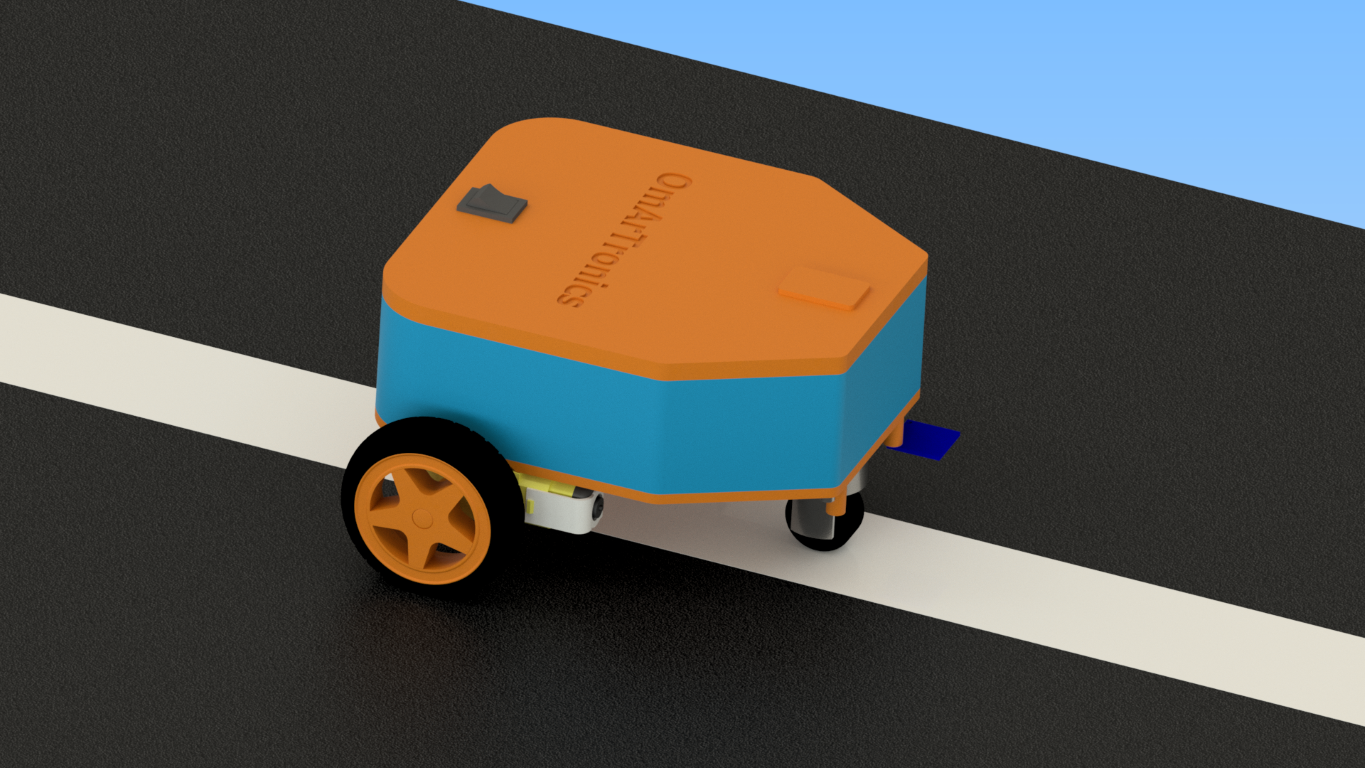
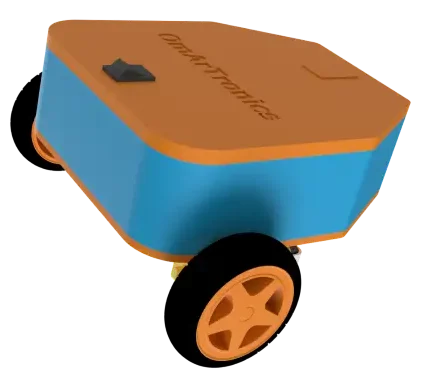
Step 1: Designing the robot in Autodesk Inventor
The robot was designed in Autodesk Inventor to make sure all components fit securely while keeping the structure lightweight and compact. The design has three custom parts:
- Chassis: A sturdy base for mounting the motors, the TCS34725 sensor, and the Arduino with its motor shield.
- Sensor Holder: Positions the TCS34725 sensor at the correct height above the ground for reliable readings. Getting the sensor height right matters a lot for accurate calibration and consistent line detection.
- Arduino Holder: Provides easy access to the Arduino Uno for programming, wiring, and debugging.
You can download the STL files for all 3D-printed parts from Cults3D or get them from our OmArTronics Shop.
Step 2: 3D printing the components
Once the design is finalized, print the components using a standard FDM 3D printer. A Creality Ender 3 or similar printer works well. PLA is the easiest material to print, while ABS offers more durability if you plan to use the robot a lot. After printing, clean the parts: remove any support material, sand rough edges, and check that all screw holes and component slots are the correct size before assembly.
Step 3: Assembling the line-following robot
Mounting the motors and wheels
- First, secure both DC motors to the chassis using M3 screws and threaded inserts. Make sure the motor shafts face outward.
- Next, press the wheels onto the motor shafts and verify that both wheels spin freely without rubbing against the chassis.
- Finally, mount the support caster wheel at the rear of the chassis to provide stable three-point balance.
Installing the electronics
- First, mount the Arduino Uno into the Arduino holder and attach the holder to the chassis.
- Then, stack the Arduino Motor Shield Rev3 on top of the Arduino Uno. Make sure all header pins are properly aligned.
- After that, attach the TCS34725 sensor module to the sensor holder and mount the holder to the front-bottom of the chassis, facing downward toward the track surface. The sensor should be approximately 10 to 15 mm above the ground for best results.
- Lastly, connect the battery and secure all components so nothing is loose during movement.
Step 4: Wiring the components
This project uses a single TCS34725 RGB sensor (not multiple sensors). The sensor connects to the Arduino via I2C, while the motors are controlled through the Motor Shield. The wiring diagram below shows the complete circuit.
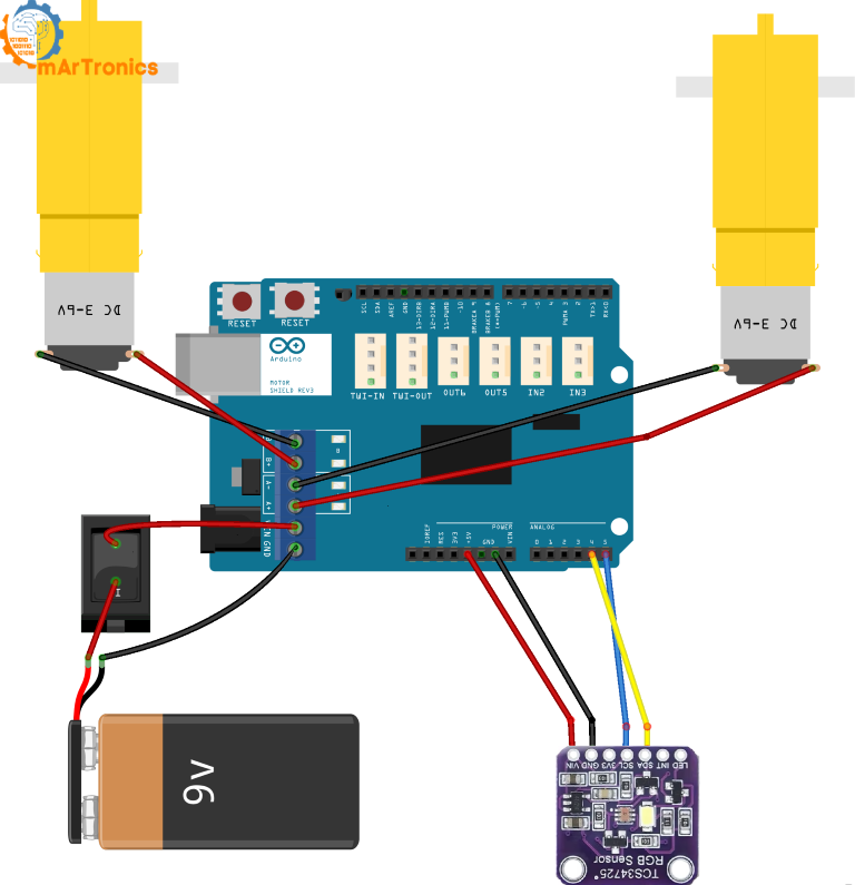
Motor connections
The DC motors connect to the motor terminals on the Arduino Motor Shield Rev3. The shield handles direction and PWM speed control through these pins:
| Motor | Shield Terminal | Direction Pin | PWM (Speed) Pin |
|---|---|---|---|
| Left Motor (Motor A) | Motor A terminal | Digital Pin 12 (DIR_A) | Digital Pin 3 (PWM_A) |
| Right Motor (Motor B) | Motor B terminal | Digital Pin 13 (DIR_B) | Digital Pin 11 (PWM_B) |
TCS34725 Sensor Connections (I2C)
The TCS34725 communicates with the Arduino over the I2C bus. Connect it as follows:
| TCS34725 Pin | Arduino Pin | Notes |
|---|---|---|
| VIN | 5V | Power supply for the sensor |
| GND | GND | Common ground |
| SDA | A4 (SDA) | I2C data line |
| SCL | A5 (SCL) | I2C clock line |
Power connections
| Component | Connection | Notes |
|---|---|---|
| Battery (7.4V LiPo or 9V) | Motor Shield external power input | Powers both motors and Arduino through the shield |
| Power Switch (optional) | In series with battery positive lead | Allows easy on/off without disconnecting the battery |
Important: This project uses one single TCS34725 sensor, not an array of multiple sensors. The sensor reads the clear channel (C) to detect overall brightness. All references to “sensor” throughout this tutorial refer to this single TCS34725 module.
Step 5: Understanding PID control for this robot
The TCS34725 RGB sensor does a good job of telling a black line apart from a white background because it measures actual light intensity. This project pairs that sensor with a PID (Proportional-Integral-Derivative) controller for smooth path following. If you built the KY-033 line-following robot, you will notice a big difference: the KY-033 version used simple on/off digital signals (line detected or not), which made the robot zig-zag. This PID-based approach instead uses continuous analog values from the TCS34725 clear channel to calculate proportional corrections, producing much smoother and more predictable motion.
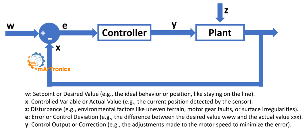
What error, setpoint, and correction mean in this robot
In this robot, the PID terms map to concrete values:
- Setpoint: The
middleValue, which is the average of the black and white calibration readings. This represents the boundary between line and background. - Process variable: The current clear-channel reading from the TCS34725 sensor.
- Error: The difference between the
middleValueand the current sensor reading. A positive error means the sensor is over the dark line; a negative error means it is over the bright background. - Correction (y): The PID output value added to one motor speed and subtracted from the other, creating differential steering.
The three PID components
Proportional (P) — Reacts to the current error. This term multiplies the current error by the gain Kp. If the sensor drifts off the line edge, the P term immediately produces a correction proportional to how far off the sensor is. Larger Kp values produce faster reactions but can cause overshooting and oscillation if set too high. The equation is: P = Kp × error.
Integral (I) — Compensates for accumulated error over time. This term sums the error over time and multiplies it by Ki. It helps when the robot consistently drifts slightly to one side because of motor differences or track asymmetry. The integral corrects this steady-state bias. In the code, the integral sum is constrained to a small range (±4) to prevent windup, and it resets when the error is small. The equation is: I = Ki × Σerror.
Derivative (D) — Predicts future error from the rate of change. This term looks at how fast the error is changing and multiplies the change rate by Kd. It acts as a damper: if the robot is swinging toward the line quickly, the D term slows down the correction to prevent overshoot. For this project, though, the derivative component is optional and secondary. P and I do most of the work, but you can increase Kd slightly if you see persistent oscillation. The equation is: D = Kd × (error − previousError).
The combined PID equation
The full PID correction combines all three terms: correction = Kp × error + Ki × Σerror + Kd × (error − previousError). This correction value is then applied to the motor speeds:
speedLeft = baseSpeed + correctionspeedRight = baseSpeed − correction
When the error is zero (sensor is right on the threshold), both motors run at the base speed and the robot drives straight. When the error is positive or negative, the correction makes one motor faster and the other slower, causing the robot to steer back toward the line.
Advantages of PID for line following
- The robot tracks the line edge accurately, even through curves.
- It eliminates the jerky zig-zag behavior you get with simple threshold-based line followers.
- It handles changes in surface reflectivity, motor inconsistencies, and battery voltage drops.
- You can tune it for different track layouts, line widths, and robot speeds by adjusting Kp, Ki, and Kd.
Step 6: Programming the line-following robot (Arduino code)
Below is the complete Arduino sketch for the TCS34725 line-following robot with PID control. Upload this code to your Arduino Uno using the Arduino IDE. Before uploading, make sure you have the Adafruit TCS34725 library and the AFMotor library installed. You can find both in the Arduino Library Manager. The full code is also available on the GitHub repository linked in the Resources section.
Complete Arduino sketch
/**
 * Author: Omar Draidrya
 * Date: 2024/12/06
 * Line-Following Robot with TCS34725.
 */
#include <Wire.h>
#include <AFMotor.h>
#include <Adafruit_TCS34725.h>
// Initialize TCS34725 sensor
Adafruit_TCS34725 tcs = Adafruit_TCS34725(TCS34725_INTEGRATIONTIME_2_4MS, TCS34725_GAIN_4X);
// Motor control pins
#define DIR_A 12
#define DIR_B 13
#define PWM_A 3
#define PWM_B 11
// PID parameters
float Kp = 24.0;  // Proportional gain
float Ki = 1.0;   // Integral gain
float Kd = 1.0;   // Derivative gain
int baseSpeed = 60;  // Base speed
// Middle value for black/white
int middleValue = 3; // Adjusted based on measured values
// Global variables for PID
float error = 0, previousError = 0, sumError = 0;
void setup() {
  Serial.begin(9600);
  // Initialize TCS34725 sensor
  if (!tcs.begin()) {
    Serial.println("Error: TCS34725 not detected. Check wiring!");
    while (1);
  }
  Serial.println("TCS34725 sensor detected!");
  // Configure motor control pins
  pinMode(DIR_A, OUTPUT);
  pinMode(DIR_B, OUTPUT);
  pinMode(PWM_A, OUTPUT);
  pinMode(PWM_B, OUTPUT);
  // Perform sensor calibration
  calibrateSensor();
}
void loop() {
  uint16_t r, g, b, c;
  tcs.getRawData(&r, &g, &b, &c);
  // Calculate error
  error = middleValue - (float)c ;
  // PID calculation
  sumError += error;
  sumError = constrain(sumError, -4, 4); // Limit integral component
  if (abs(error) < 2.0) {
    sumError = 0; // Reset for small errors
  }
  float differential = error - previousError;
  float correction = Kp * error + Ki * sumError + Kd * differential;
  previousError = error;
  // Adjust motor speeds
  int speedLeft = baseSpeed + (int)correction;
  int speedRight = baseSpeed - (int)correction;
  speedLeft = constrain(speedLeft, 20, 255);
  speedRight = constrain(speedRight, 20, 255);
  controlMotors(speedLeft, speedRight);
}
void calibrateSensor() {
  uint16_t r, g, b, c;
  // Measure black value
  Serial.println("Calibrating: Measuring black value...");
  controlMotors(-85, 85); // Slightly turn left
  delay(350);
   // Stop motors after calibration
  controlMotors(0, 0);
  delay(50);
  tcs.getRawData(&r, &g, &b, &c);
  int blackValue = c;
  Serial.print("Black Value: ");
  Serial.println(blackValue);
  // Measure white value
  Serial.println("Calibrating: Measuring white value...");
  controlMotors(85, -85); // Slightly turn right
  delay(500);
    // Stop motors after calibration
  controlMotors(0, 0);
  delay(50);
  tcs.getRawData(&r, &g, &b, &c);
  int whiteValue = c;
  Serial.print("White Value: ");
  Serial.println(whiteValue);
  // Calculate middle value
  middleValue = (blackValue + whiteValue) / 2;
  Serial.print("Middle Value: ");
  Serial.println(middleValue);
  // Stop motors after calibration
  controlMotors(0, 0);
}
void controlMotors(int speedLeft, int speedRight) {
  if (speedLeft >= 0) {
    digitalWrite(DIR_A, HIGH);
  } else {
    digitalWrite(DIR_A, LOW);
    speedLeft = abs(speedLeft);
  }
  if (speedRight >= 0) {
    digitalWrite(DIR_B, HIGH);
  } else {
    digitalWrite(DIR_B, LOW);
    speedRight = abs(speedRight);
  }
  analogWrite(PWM_A, speedLeft);
  analogWrite(PWM_B, speedRight);
}
Code walkthrough
Let’s walk through each section of the code so you understand how the TCS34725 sensor-based line-following robot works:
Sensor initialization
Adafruit_TCS34725 tcs = Adafruit_TCS34725(TCS34725_INTEGRATIONTIME_2_4MS, TCS34725_GAIN_4X);
The TCS34725 sensor is initialized with a very short integration time (2.4 ms) and moderate gain (4×). The short integration time means the sensor takes readings extremely quickly, which matters because a moving robot needs to respond to line changes fast. The 4× gain amplifies the signal enough to tell black from white without saturating the sensor on bright surfaces. If your readings seem too low or too high, try different gain settings (1×, 4×, 16×, or 60×).
Motor pin definitions
#define DIR_A 12
#define DIR_B 13
#define PWM_A 3
#define PWM_B 11
These pin definitions match the Arduino Motor Shield Rev3 layout. DIR_A and DIR_B control the rotation direction of each motor (HIGH for forward, LOW for reverse). PWM_A and PWM_B control the speed of each motor using pulse-width modulation (PWM), where 0 means stopped and 255 means full speed. So the PID correction adjusts these PWM values independently for each motor to steer.
Calibration routine
void calibrateSensor() {
  // Measures the light intensity for black and white areas.
  // Calculates the middle value (threshold) as the average of the two.
}
The calibration function is one of the most important parts of the code. When the robot powers on, it performs these steps automatically:
- Measure the black (dark) value: The robot rotates slightly to the left for 350 ms, positioning the sensor over the dark surface area. It then stops and takes a clear-channel reading, which becomes the
blackValue. - Measure the white (bright) value: The robot rotates to the right for 500 ms (slightly longer to also cover the white tape). It stops and takes another reading, which becomes the
whiteValue. - Calculate the threshold: The
middleValueis set to the average of the black and white readings. This threshold is the dividing line between “on the dark line” and “on the bright background” for all PID calculations that follow.
Important placement note: Before powering on the robot, place it so the sensor starts at the left edge of the white tape on the dark surface. The calibration assumes the robot will first read a dark area (left turn) and then a bright area (right turn). If the robot is placed in the wrong position, calibration will give incorrect values and the robot will not follow the line correctly.
Main loop and error calculation
void loop() {
  uint16_t r, g, b, c;
  tcs.getRawData(&r, &g, &b, &c);
  // Reads the light intensity from the sensor.
  // Calculates error and adjusts motor speeds using PID control.
}
In every loop iteration, the sensor reads the red, green, blue, and clear channels, but only the clear channel c is used because it gives a reliable overall brightness measurement. The error is calculated as middleValue - c: when the sensor is over the dark line, c is low and the error is positive; when it is over the bright background, c is high and the error is negative. This signed error then drives the PID correction to steer the robot in the right direction.
PID correction calculation
float correction = Kp * error + Ki * sumError + Kd * differential;
This single line is the core of the PID controller. It combines proportional, integral, and derivative terms into one correction value. The integral sum (sumError) is constrained between -4 and 4 to prevent integral windup, which could cause the robot to overshoot badly after a long turn. Also, when the error is very small (less than 2.0), the integral sum resets to zero so accumulated correction does not build up when the robot is already tracking well.
Speed limiting
After the PID correction is applied to the base speed, both motor speeds are constrained to a range of 20 to 255 using the constrain() function. The minimum of 20 is there because very low PWM values may not produce any motion due to motor friction. The maximum of 255 is the Arduino PWM limit.
Motor control function
void controlMotors(int speedLeft, int speedRight) {
  // Adjusts motor direction and speed based on the calculated correction.
}
The controlMotors() function accepts signed speed values for each motor. Positive values drive the motor forward; negative values drive it in reverse (used during calibration turns). So the function sets the direction pin (HIGH or LOW) and then applies the absolute speed value via PWM. This way, the same function handles forward driving, turning, and the calibration rotation maneuvers.
Step 7: Calibration – how the robot learns the track
Calibration matters because the absolute sensor readings change depending on lighting conditions, sensor height, surface color, and tape material. Instead of hardcoding a fixed threshold, the robot measures the actual environment at startup and then calculates the threshold dynamically.
Before calibration: correct placement
Place the robot so the TCS34725 sensor is positioned at the left edge of the white tape, with the dark surface to the left and the white tape to the right. This ensures that when the robot rotates left during calibration, the sensor reads the dark background, and when it rotates right, it reads the white tape.
What the calibration routine does
- Rotates the robot left for 350 ms and records the clear-channel reading as
blackValue. - Rotates the robot right for 500 ms and records the clear-channel reading as
whiteValue. - Calculates
middleValue = (blackValue + whiteValue) / 2. - Prints all three values to the Serial Monitor so you can verify correct calibration.
What to do if calibration gives poor values
- If the black and white values are very close together, the sensor cannot tell the line from the background. Check the sensor height (should be 10–15 mm above the surface), make sure the line has strong contrast, and verify the sensor is working by checking raw values in the Serial Monitor.
- If the values seem reversed (black value higher than white value), the robot may have been placed in the wrong starting position, or the rotation times need adjustment.
- If the sensor always returns very low or zero values, check the I2C wiring (SDA to A4, SCL to A5) and confirm the sensor is detected at startup.
Step 8: How to test and tune the robot
Overall, testing and tuning are where your line-following robot goes from “working” to “working well.” Follow this process to get the best performance from your DIY line follower robot with PID.
Setting up the test track
- Use a 50 mm wide white adhesive tape on a dark, non-reflective surface. This provides strong contrast for the TCS34725 sensor.
- Start with a simple oval or gentle curve layout. Avoid sharp 90-degree turns until the PID is tuned.
- Make sure the track surface is evenly lit. Shadows or bright spotlights can confuse the sensor readings.
Tuning the PID parameters
PID tuning is an iterative process. The default values in the code (Kp = 24.0, Ki = 1.0, Kd = 1.0) are a good starting point, but you may need to adjust them for your specific setup.
- Start with Kp only. Set Ki = 0 and Kd = 0. Then, gradually increase Kp from a low value (e.g., 5) until the robot begins to follow the line. If it overshoots and oscillates, reduce Kp slightly.
- Add Ki carefully. If the robot consistently drifts to one side or misses gentle curves, increase Ki in small increments (e.g., 0.5). Too much Ki causes slow oscillation and instability.
- Add Kd only if needed. If the robot oscillates even after tuning Kp, a small Kd value (e.g., 0.5 to 2.0) can dampen the oscillation. Avoid setting Kd too high, as it can make the robot sluggish or jittery.
- Reduce base speed during early tests. A lower
baseSpeed(e.g., 40–60) gives the PID controller more time to react. Once tuned, you can gradually increase the speed. - Watch for oscillation vs. sluggishness. If the robot zig-zags rapidly around the line, Kp is too high or Kd is too low. If the robot reacts too slowly and misses curves, Kp is too low.
Open the Serial Monitor at 9600 baud while testing. The calibration values and error readings will help you understand what the robot is seeing and how to adjust the PID gains accordingly.
Troubleshooting common issues
If your robot is not performing as expected, the following tables summarize the most common problems and their solutions:
| Problem | Possible Cause | Solution |
|---|---|---|
| Robot does not follow the line at all | Sensor not detected, wrong wiring, or failed calibration | Check I2C wiring (SDA→A4, SCL→A5). Open Serial Monitor to verify sensor detection and calibration values. Reposition the robot and recalibrate. |
| Robot oscillates heavily around the line | Kp is too high or Kd is too low | Reduce Kp by 20–30%. Add a small Kd value (0.5–2.0) to dampen oscillation. |
| Robot reacts too slowly and misses curves | Kp is too low or base speed is too high | Increase Kp gradually. Reduce baseSpeed to give the PID more reaction time. |
| Sensor readings seem unstable or noisy | Sensor too far from surface, ambient light interference, or loose wiring | Lower the sensor to 10–15 mm above the track. Shield the sensor from overhead lights. Check all wire connections. |
| Robot calibrates incorrectly | Wrong starting position or insufficient contrast | Place the robot at the left edge of the white tape on the dark surface. Ensure the tape is truly white and the background is truly dark. |
Motor, power, and track issues
| Problem | Possible Cause | Solution |
|---|---|---|
| Motors are too weak or do not move | Low battery, PWM value too low, or motor wiring reversed | Charge or replace the battery. Check that minimum speed (20) is enough for your motors. Swap motor wires if direction is wrong. |
| One motor runs faster than the other | Motor hardware differences or wiring issue | This is normal for cheap motors. The integral (Ki) term in the PID helps correct this drift. You can also adjust the base speed offset in code. |
| Robot drives in circles during calibration | One motor is wired in reverse | Swap the positive and negative wires for the motor that turns in the wrong direction. |
| Line contrast is insufficient | Tape color too similar to background, or glossy surface causes reflections | Use matte white tape on a matte dark surface. Avoid glossy floors or metallic tape. |
| Power issues cause inconsistent behavior | Battery voltage dropping during motor use | Use a fully charged LiPo battery. A 9V block battery may not provide enough current for both motors. Consider a battery voltage monitor. |
Frequently asked questions (FAQ)
The TCS34725 is an RGB color and clear light sensor that communicates over I2C. Unlike basic IR sensors, it provides analog light intensity values, so line detection is more precise.
PID stands for Proportional-Integral-Derivative. It is a feedback control algorithm that adjusts motor speeds proportionally to how far off the line the sensor is, so the robot follows the line smoothly instead of zig-zagging.
Yes. You can use the Arduino Mega or Nano if they support I2C. However, the Motor Shield Rev3 stacks directly on the Uno or Mega. If you use a Nano, you will need to wire the motor connections manually.
The TCS34725 has a fixed I2C address, so you cannot connect two sensors directly without an I2C multiplexer (such as the TCA9548A). This project uses a single sensor, which is enough for standard tracks.
If the robot follows the line smoothly without excessive oscillation, your values are good. Rapid zig-zagging means Kp is too high, while drifting off curves means Kp is too low. Use the Serial Monitor to watch error values while tuning.
Yes. Since the TCS34725 provides red, green, blue, and clear channel data, you can use specific color channels instead of the clear channel. For example, to follow a red line, use the red channel relative to the green and blue channels. This requires changes to the error calculation logic.
Resources and downloads
- GitHub Repository: Full Arduino code for this project is available on GitHub.
- STL Files: Download the 3D-printable chassis, sensor holder, and Arduino holder from Cults3D or from our OmArTronics Shop.
- Adafruit TCS34725 Library: Install via Arduino IDE Library Manager (search for “Adafruit TCS34725”).
- AFMotor Library: Install via Arduino IDE Library Manager (search for “Adafruit Motor Shield”).
Related OmArTronics tutorials
If you liked this project, check out these related tutorials to keep building your robotics skills:
- Building a Line-Following Robot with KY-033 Sensors for Beginners – The beginner version of this project, using simpler IR sensors without PID control.
- Building the Bluetooth-Controlled Robot Car OmObi – Learn how to build a mobile robot you can control via Bluetooth and a smartphone app.
- OmObiArm: Mobile Robot with Integrated Robotic Arm – A more advanced mobile robot project that combines a driving platform with a robotic arm.
- Control a Servo Motor with Joystick and OLED Display – Learn Arduino basics with servos, joystick input, and display output.
- DIY 6-DOF Robotic Arm with Bluetooth Control – Build and program a full robotic arm with six degrees of freedom.
Conclusion
You have now built a complete TCS34725 line-following robot with Arduino and PID control. This tutorial took you through 3D design, printing, assembly, wiring, sensor calibration, PID theory, Arduino programming, testing, and tuning. Compared to the basic IR-based line follower, this robot tracks lines much more smoothly because of the continuous analog readings from the TCS34725 sensor and the proportional corrections from the PID controller.
From here, you can experiment with faster base speeds, tighter track curves, colored line detection using the RGB channels, or adding multiple sensors with an I2C multiplexer. You can also check out other OmArTronics robotics projects for more Arduino, mechatronics, and mobile robot builds.
Download the 3D Print Files (STL)
All 3D-printable STL files for this project are available for download. You can get them from our shop or browse them on Cults3D:
- OmArTronics Shop: Download project files from OmArTronics – Get the complete project package including STL files, wiring diagrams, and source code delivered to your email.
- Cults3D: View on Cults3D – Browse and download the 3D model files on Cults3D.
1 thought on “Building a Line Following Robot with TCS34725 RGB Sensor”