
OmArm Zero Series Part 1: Build · Part 2: URDF + RViz + Gazebo · Part 3: MoveIt 2 (this post) · Part 4: Computer Vision (coming soon)

At a glance
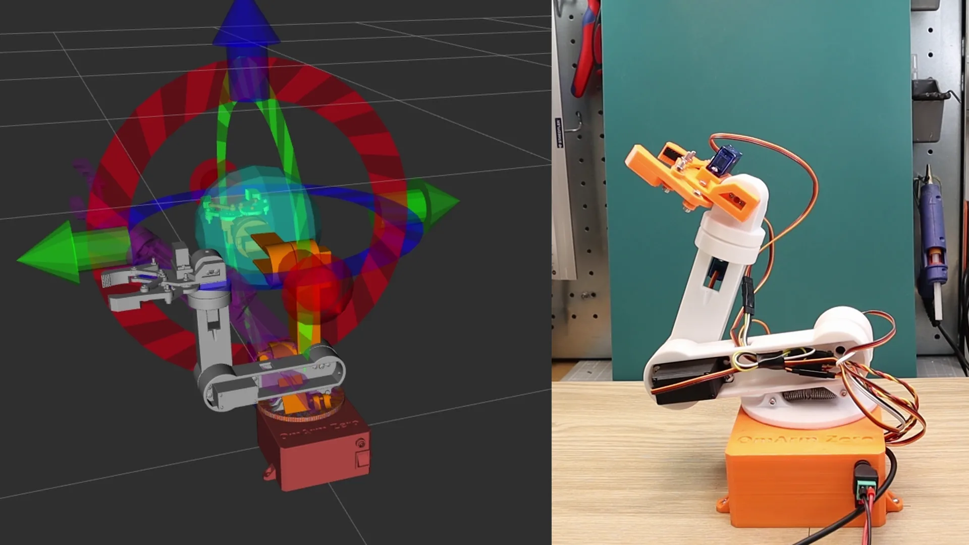
What you’ll build: A fully configured MoveIt 2 setup for the OmArm Zero robot arm. You’ll go from understanding inverse kinematics to planning collision-free trajectories in RViz and executing them on both a Gazebo simulation and the real hardware over serial.
Prerequisites: Completed Part 2 (URDF, RViz, Gazebo working). You should be able to launch the Gazebo simulation and see the arm respond to joint trajectory commands.
Software: Ubuntu 24.04, ROS 2 Jazzy, Gazebo Harmonic, MoveIt 2
Time: 3-5 hours (config + calibration + real hardware testing)
Difficulty: Intermediate to advanced. You’ll configure motion planning, understand controller architecture, and bridge software to physical servos.
Files: Full ROS 2 workspace in the shop (free download, link at the end)
Table of contents
- From joint sliders to motion planning
- Inverse kinematics: the real problem
- Trajectory planning: not just the destination
- What MoveIt 2 actually does
- MoveIt Setup Assistant: configuring your robot
- Understanding the config files
- Controller configuration
- Gripper and mimic joints
- MoveIt demo: mock hardware
- MoveIt + Gazebo simulation
- MoveIt Python API: scripting motion
- Bridge architecture: MoveIt to real hardware
- Servo calibration
- Real robot launch: everything together
- استكشاف الأخطاء وإصلاحها
- الأسئلة المتداولة
1. From joint sliders to motion planning
In Part 2 we built the digital twin. We could move every joint with sliders in RViz, simulate physics in Gazebo, and send joint trajectory commands. That works for testing individual joints, but it’s not how robots actually work in the real world.
Think about what we were doing: we picked joint angles manually and watched where the gripper ended up. That’s forward kinematics, or direct kinematics. You set the inputs (joint angles) and observe the output (gripper position). It’s useful for understanding the arm’s geometry, but it’s backwards from what you actually need.
When a robot picks up a cup from a table, nobody sits there thinking “okay, shoulder to 45 degrees, elbow to -60, wrist to…” You think about where the gripper needs to go. The cup is at position X, Y, Z. The gripper needs to reach it with a specific orientation. The joint angles? That’s the robot’s problem to figure out.
This is the fundamental shift from Part 2 to Part 3. We stop thinking in joint space and start thinking in task space. And the tool that makes this possible is MoveIt 2.
2. Inverse kinematics: the real problem
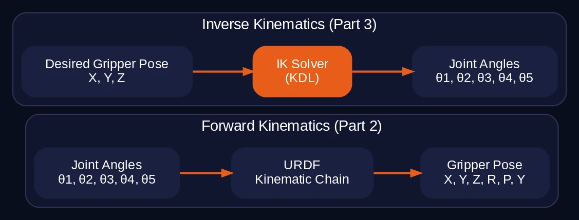
Forward kinematics is straightforward. You have the joint angles and the URDF description (link lengths, joint axes, offsets). Chain the transforms together and you get the gripper pose. One input, one output, always solvable. We actually saw this in Part 2 when robot_state_publisher computed the TF tree from joint states.
Inverse kinematics is the opposite: given a desired gripper position and orientation, find the joint angles that get you there. This is where things get interesting.
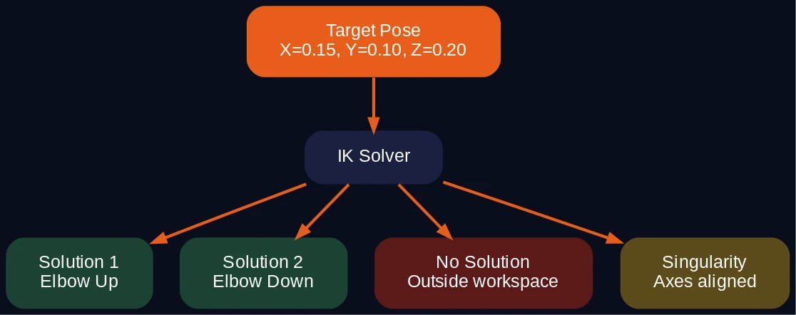
Three things make IK harder than FK:
Multiple solutions. For any reachable gripper pose, there are usually several valid joint configurations. Think of touching your nose. Your elbow could point left, right, up, or down. Same fingertip position, different arm configurations. A 6-DOF arm like the OmArm Zero can have up to 16 solutions for a single end-effector pose.
No solution. If the target is outside the workspace, or the required orientation is impossible given the joint limits, there’s simply no answer. The solver has to recognize this and report failure instead of returning garbage.
Singularities. Certain configurations where two joint axes align and the arm loses a degree of freedom. Near singularities, tiny changes in the target cause wild swings in joint angles. The math breaks down.
You can solve IK analytically for simple arms by working through the trigonometry by hand. For a 6-DOF arm with arbitrary link lengths and offsets, the closed-form equations get ugly fast. That’s why numerical solvers exist.
MoveIt 2 uses the KDL solver (Kinematics and Dynamics Library) for the OmArm Zero. KDL takes the URDF, builds a kinematic chain, and uses iterative Newton-Raphson methods to converge on a solution. You don’t write the math. You point KDL at your URDF and it figures out the rest.
# kinematics.yaml -- the entire IK configuration
arm:
  kinematics_solver: kdl_kinematics_plugin/KDLKinematicsPlugin
  position_only_ik: true
  kinematics_solver_search_resolution: 0.005
  kinematics_solver_timeout: 0.2
  kinematics_solver_attempts: 10
position_only_ik: true means we only care about the gripper’s XYZ position, not its full 6-DOF pose. For a 5-DOF arm (five revolute joints in the arm group, no wrist roll), constraining all six pose components would be overconstrained. The solver would fail on most targets.
3. Trajectory planning: not just the destination
IK gives you the joint angles for a target pose. But knowing where to go is only half the problem. The other half: how do you get there?
You can’t just jump from the current joint angles to the target angles. If you send all joints to their target positions simultaneously, the arm might collide with itself, hit the table, or exceed velocity limits. The motion needs to be planned.
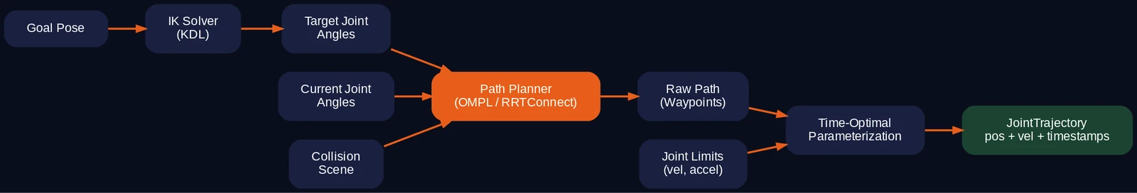
A trajectory planner does three things:
Path planning. Find a collision-free path through joint space from the current configuration to the goal. This is a search problem. The arm has 5 degrees of freedom, so the search space is 5-dimensional. The planner samples random configurations, checks them against the collision model (the URDF + any obstacles you’ve added to the scene), and connects valid samples into a path.
MoveIt uses OMPL (Open Motion Planning Library) for this. The default algorithm is RRTConnect (Rapidly-exploring Random Tree), which grows two trees from start and goal and connects them. It’s fast and reliable for arms with moderate DOF.
Trajectory smoothing. The raw path from RRTConnect is a sequence of waypoints with sharp corners. Not good for servos. MoveIt applies TimeOptimalParameterization to smooth the path and add timing information. The result respects joint velocity and acceleration limits from joint_limits.yaml.
Collision checking. Every sampled configuration is checked against the robot’s self-collision model (from the SRDF) and any scene objects. If you add a table as a collision object, the planner avoids it automatically.
The output is a JointTrajectory message: a list of waypoints, each with joint positions, velocities, and a timestamp. This is what gets sent to the controller for execution.
4. What MoveIt 2 actually does
MoveIt 2 is the layer between “I want the gripper at position X” and “these specific servo angles need to change in this specific order at this specific speed.” It combines three functions into one framework:
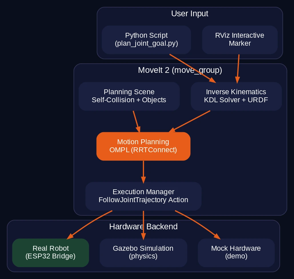
Inverse kinematics. Given a target pose, compute joint angles using the KDL solver and the URDF kinematic chain.
Motion planning. Given current and target joint configurations, find a collision-free, time-optimal trajectory using OMPL algorithms.
Execution. Send the planned trajectory to a controller via the FollowJointTrajectory action interface. Monitor execution and report success or failure.
On top of that, MoveIt manages the planning scene (collision objects like tables, walls, or other robots), planning groups (you can plan for the arm and gripper independently), and an interactive RViz plugin where you can drag the end-effector to a target pose and hit “Plan & Execute.”
Here’s the key insight: MoveIt doesn’t care what’s behind the controller interface. It could be a Gazebo simulation, mock hardware, or a real robot. As long as something responds to FollowJointTrajectory action goals, MoveIt will plan and send trajectories to it. This is what lets us use the exact same planning configuration for simulation and real hardware.
5. MoveIt Setup Assistant: configuring your robot
The MoveIt Setup Assistant is a graphical tool that reads your URDF and generates a complete MoveIt configuration package. Instead of writing YAML files by hand, you click through a wizard. Here’s exactly how the omarm_zero_moveit_config package was created.
Prerequisites
Install MoveIt 2 and the Setup Assistant:
sudo apt install ros-jazzy-moveit ros-jazzy-moveit-setup-assistant -y
Step 1: Launch the Setup Assistant
source /opt/ros/jazzy/setup.bash
source ~/omarm_zero_ws/install/setup.bash
ros2 launch moveit_setup_assistant setup_assistant.launch.py
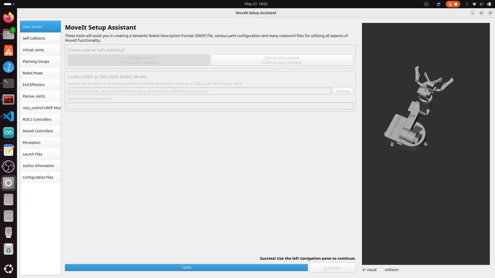
Click Create New MoveIt Configuration Package. Browse to your URDF/Xacro file:
~/omarm_zero_ws/src/omarm_zero_description/urdf/omarm_zero.xacro
Click Load Files. The robot model appears in the 3D view. If it’s all white or missing meshes, check that omarm_zero_description is built and sourced.
Step 2: Self-Collision Matrix
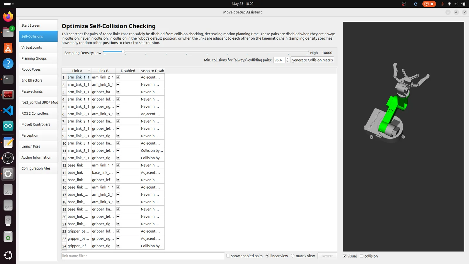
Click Self-Collisions in the left panel, then Generate Collision Matrix. The assistant samples thousands of random joint configurations and checks which link pairs can never collide. These pairs get disabled to speed up planning.
For the OmArm Zero, 10 collision pairs are disabled:
- Adjacent links (base ↔ upper base, upper base ↔ arm link 1, etc.)
- Gripper fingers that never reach certain arm links
- The two gripper fingers against each other (they’re meant to be close)
Step 3: Virtual Joint
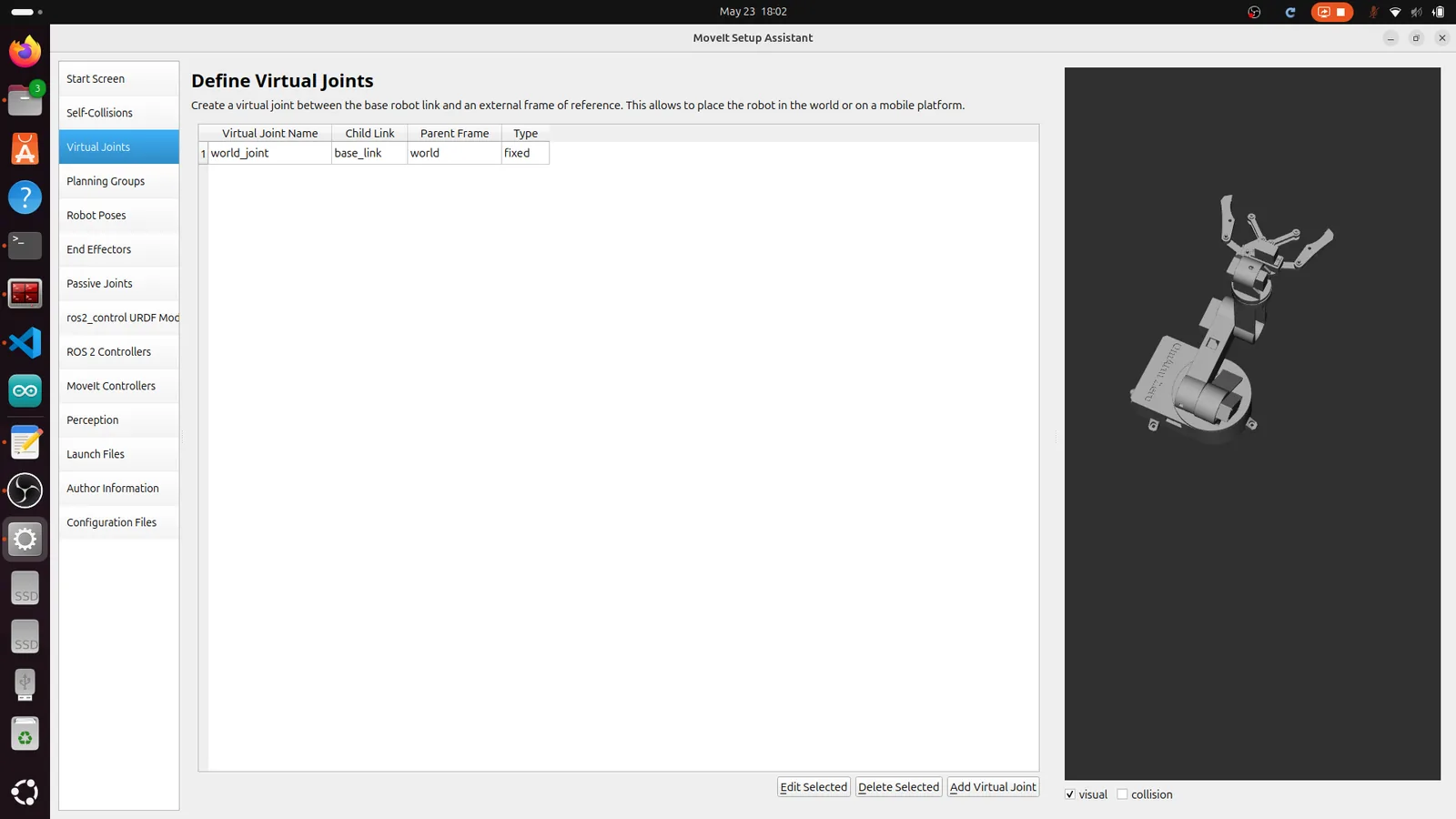
Click Virtual Joints. Add one:
| Field | القيمة |
|---|---|
| Name | world_joint |
| Child Link | base_link |
| Parent Frame | world |
| يكتب | fixed |
This anchors the robot to the world. Without it, MoveIt doesn’t know where the base is.
Step 4: Planning Groups
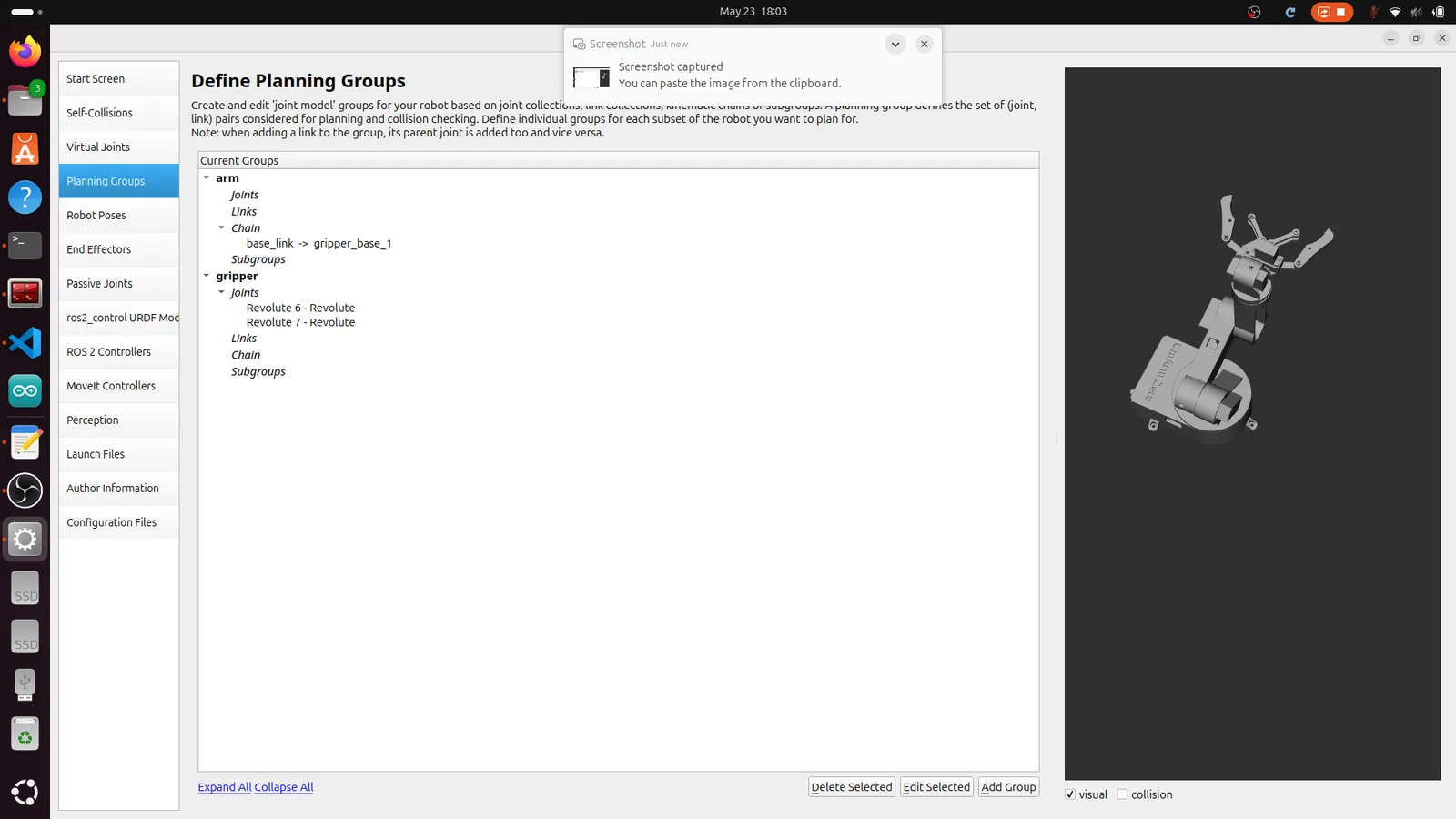
Click Planning Groups. Create two groups:
Group “arm”:
| Field | القيمة |
|---|---|
| Name | arm |
| Kinematic Solver | kdl_kinematics_plugin/KDLKinematicsPlugin |
| Group Default Planner | RRTConnect |
| Definition | Kinematic Chain |
| Base Link | base_link |
| Tip Link | gripper_base_1 |
This creates a chain through Revolute 1 → 2 → 3 → 4 → 5. The chain stops at gripper_base_1 because that’s where the arm ends and the gripper begins.
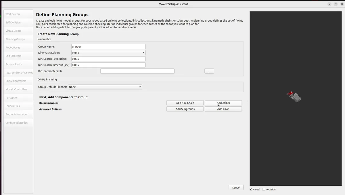
Group “gripper”:
| Field | القيمة |
|---|---|
| Name | gripper |
| Definition | Joints |
| Joints | Revolute 6, Revolute 7 |
The gripper is defined by individual joints, not a chain, because both fingers are parallel (not serial).
Step 5: Robot Poses
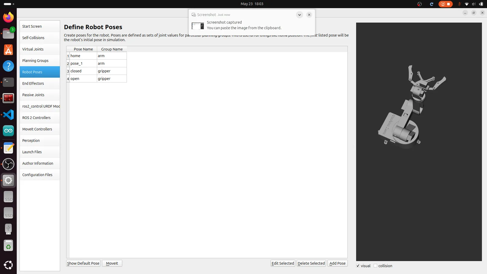
Click Robot Poses. Define named configurations that you can recall later:
“home” (group: arm):
| مشترك | Value (rad) |
|---|---|
| Revolute 1 | 0.8 |
| Revolute 2 | -0.8 |
| Revolute 3 | -1.2 |
| Revolute 4 | -0.8 |
| Revolute 5 | -2.6 |
“open” (group: gripper):
| مشترك | Value (rad) |
|---|---|
| Revolute 6 | 0.1 |
| Revolute 7 | 0.1 |
“closed” (group: gripper):
| مشترك | Value (rad) |
|---|---|
| Revolute 6 | -0.35 |
| Revolute 7 | -0.35 |
Use the sliders to find poses that make sense for your arm. “home” should be a safe resting position where nothing is at a joint limit.
Step 6: End Effector
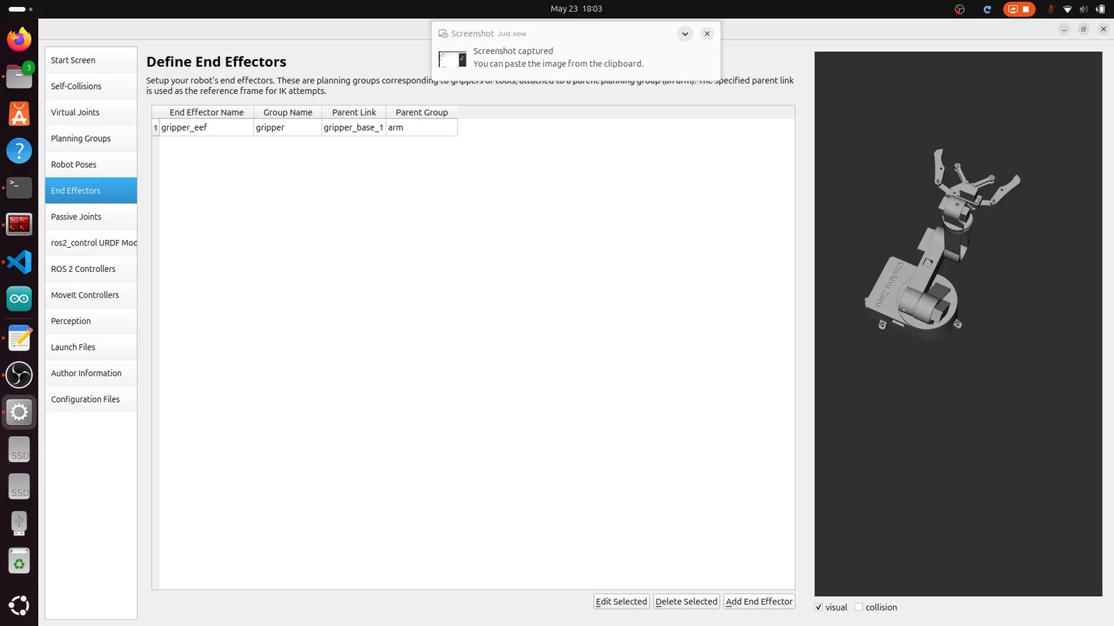
Click End Effectors. Add one:
| Field | القيمة |
|---|---|
| Name | gripper_eef |
| End Effector Group | gripper |
| Parent Link | gripper_base_1 |
| Parent Group | arm |
This tells MoveIt that the gripper is attached to the end of the arm chain. When you plan for the arm group, MoveIt knows the gripper follows along.
Step 7: Passive Joints
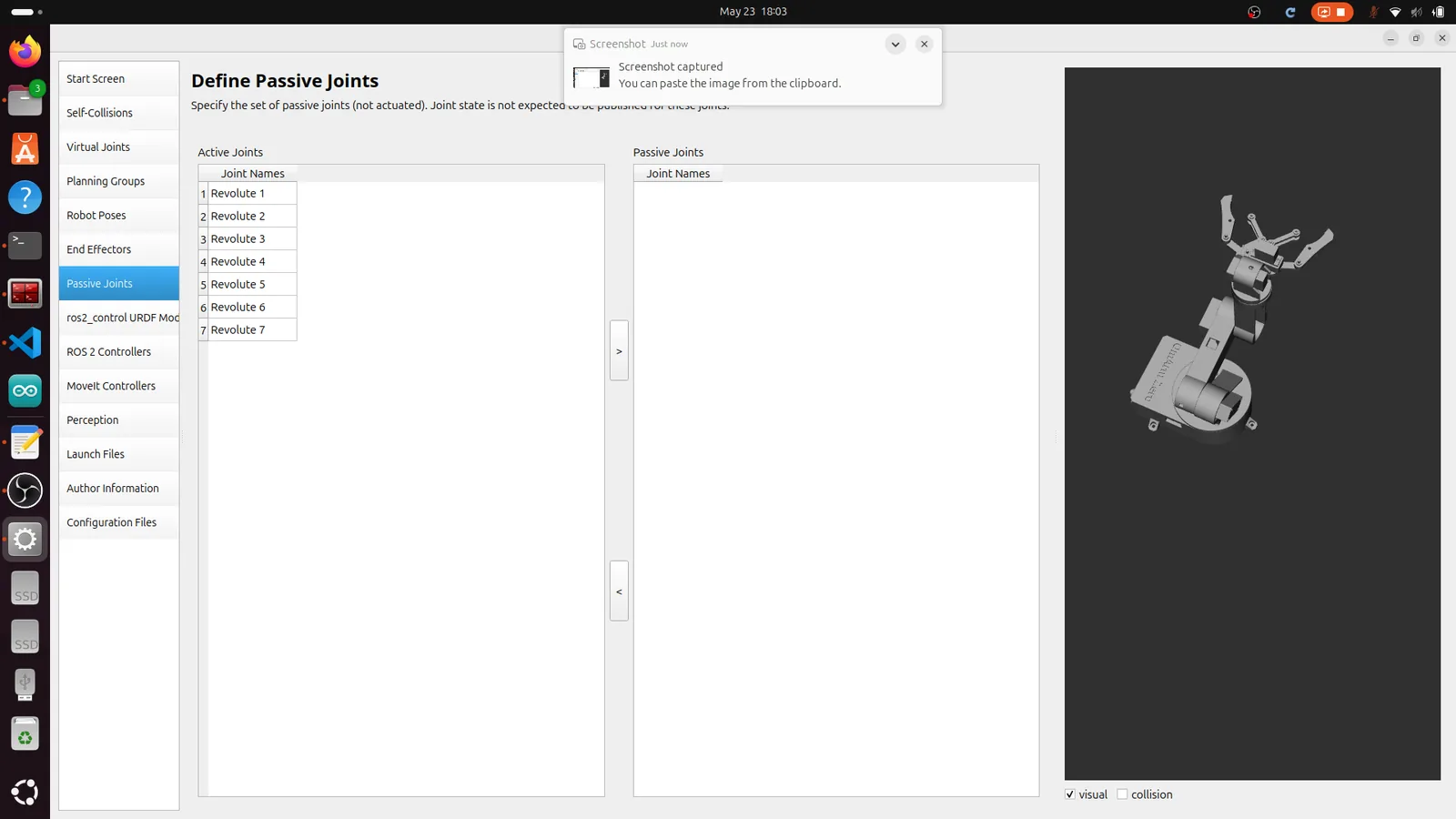
Click Passive Joints. This screen lets you mark joints that are not actuated — joints that move freely or are driven by other joints (like a caster wheel). For the OmArm Zero, all seven Revolute joints are actively driven by servos, so leave them all in the Active Joints column. Don’t move anything to the Passive Joints side.
Step 8: ros2_control URDF Modifications
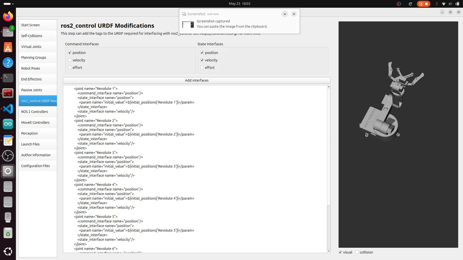
Click ros2_control URDF Mod. This step adds the <ros2_control> tag to your URDF, which defines the hardware interface for each joint. Select:
| Field | القيمة |
|---|---|
| Command Interfaces | position (checked) |
| State Interfaces | position (checked), velocity (checked) |
The assistant generates XML that declares a position command interface and position + velocity state interfaces for every joint. This matches the JointTrajectoryController configuration — you send position commands, and the controller reads back position and velocity states.
Step 9: ROS 2 Controllers
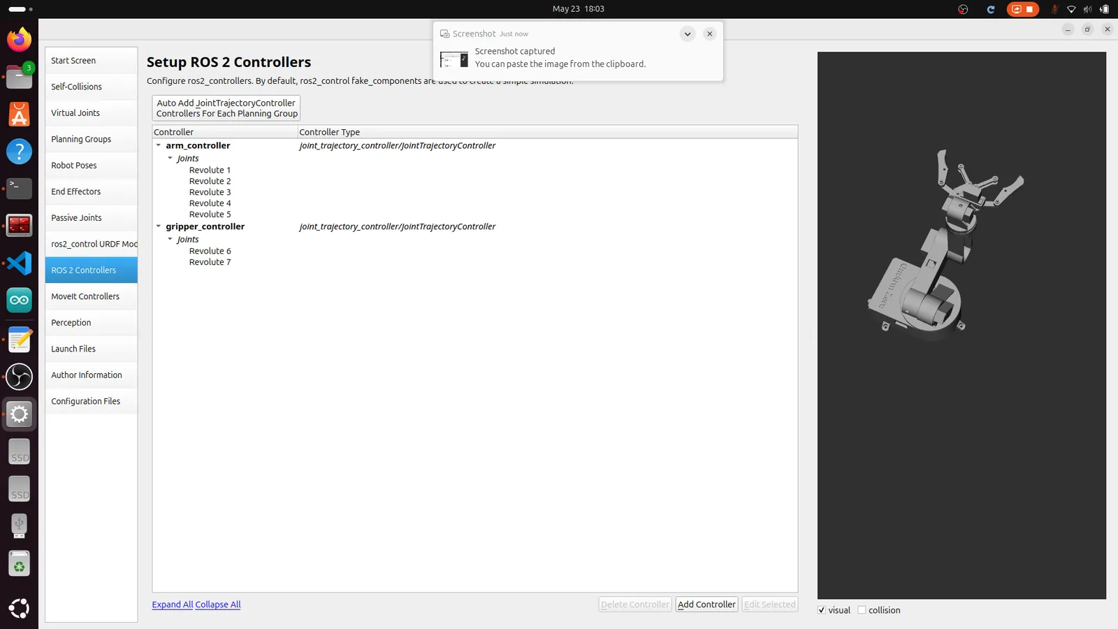
Click ROS 2 Controllers. Create two controllers:
arm_controller:
| Field | القيمة |
|---|---|
| Name | arm_controller |
| يكتب | joint_trajectory_controller/JointTrajectoryController |
| Joints | Revolute 1, Revolute 2, Revolute 3, Revolute 4, Revolute 5 |
gripper_controller:
| Field | القيمة |
|---|---|
| Name | gripper_controller |
| يكتب | joint_trajectory_controller/JointTrajectoryController |
| Joints | Revolute 6, Revolute 7 |
Separating arm and gripper into two controllers lets you move the arm without touching the gripper, and vice versa. Both use JointTrajectoryController, which accepts trajectory messages and interpolates between waypoints.
Step 10: MoveIt Controllers
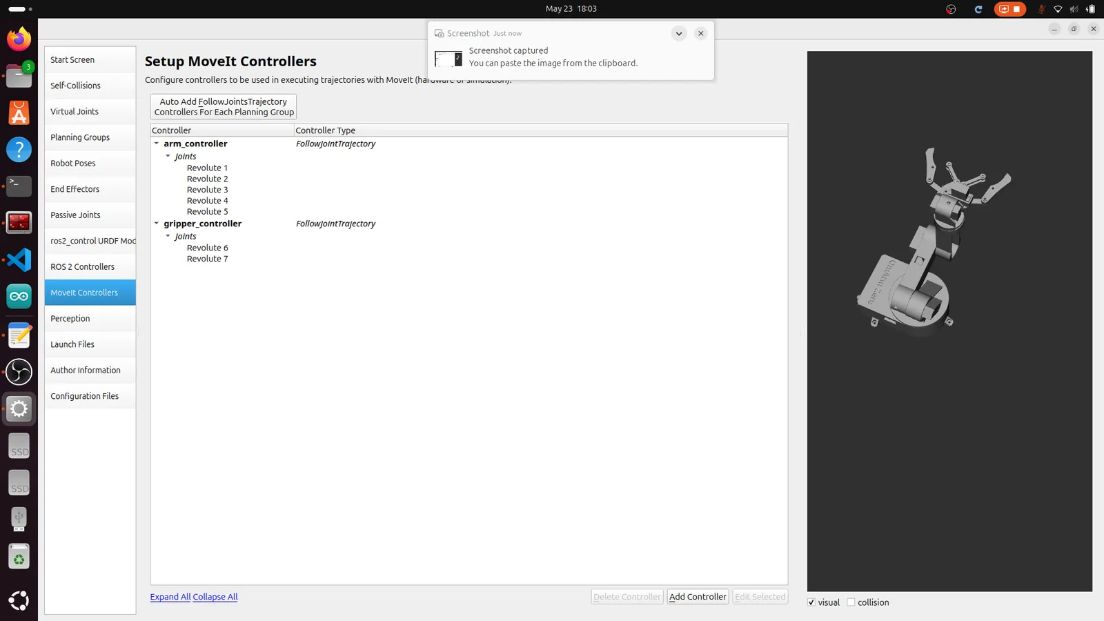
Click MoveIt Controllers. This maps MoveIt’s planning output to the ROS 2 controllers you just defined. Create two entries:
arm_controller:
| Field | القيمة |
|---|---|
| Name | arm_controller |
| Action Type | FollowJointTrajectory |
| Joints | Revolute 1 من خلال Revolute 5 |
gripper_controller:
| Field | القيمة |
|---|---|
| Name | gripper_controller |
| Action Type | FollowJointTrajectory |
| Joints | Revolute 6, Revolute 7 |
When MoveIt plans a trajectory, it sends a FollowJointTrajectory action goal to the matching controller. The controller executes the trajectory and reports back success or failure.
Step 11: Perception
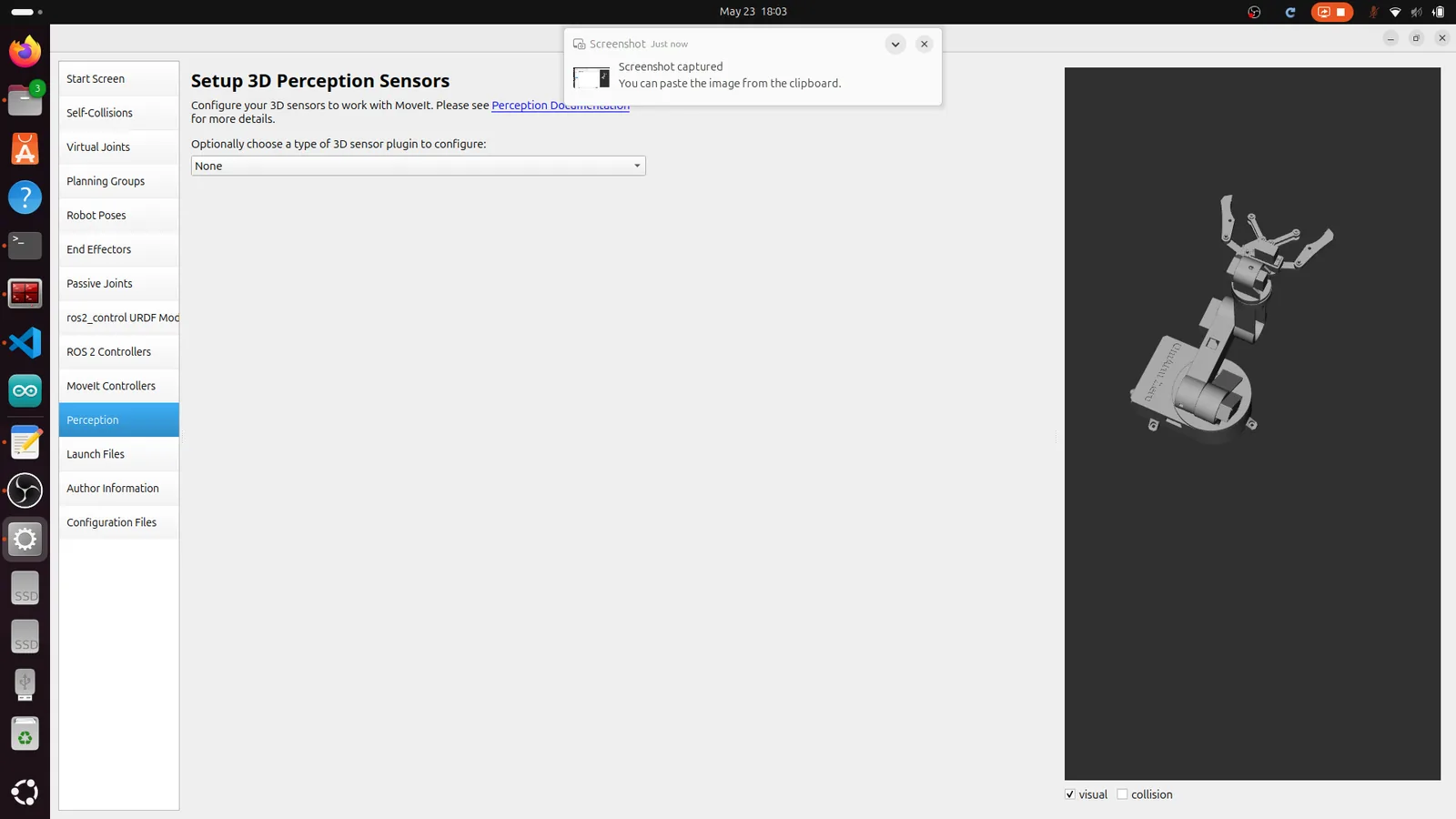
Click Perception. This configures 3D sensors (like depth cameras or point cloud sensors) for collision avoidance during motion planning. The OmArm Zero doesn’t have a 3D sensor yet — that comes in Part 4 with the camera. Set the dropdown to None and move on.
Step 12: Launch Files
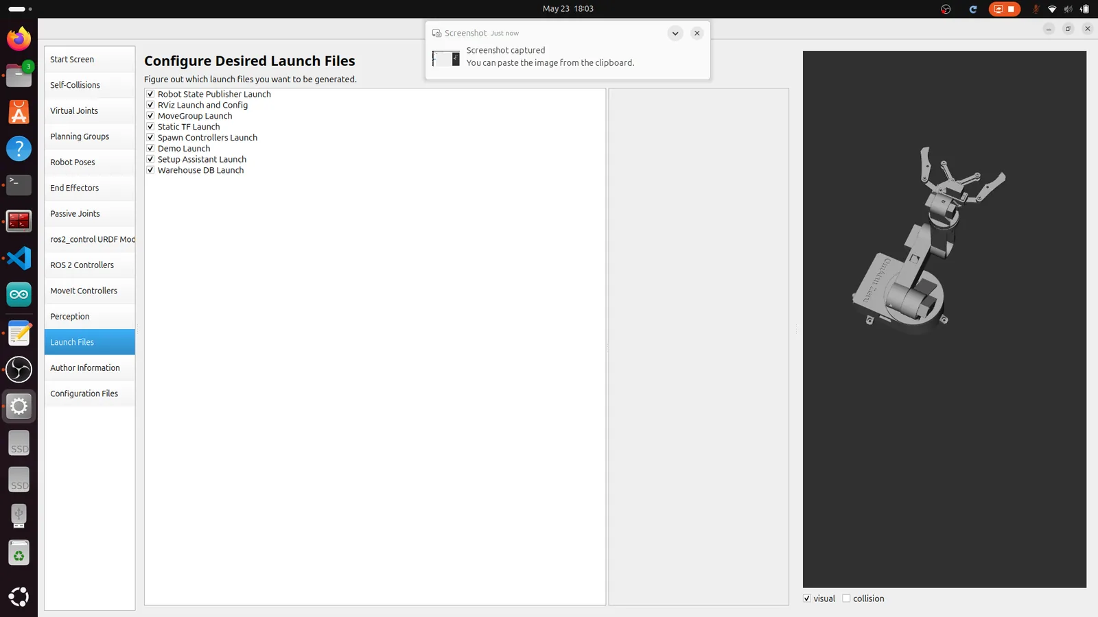
Click Launch Files. All eight launch files should be checked:
- Robot State Publisher Launch
- RViz Launch and Config
- MoveGroup Launch
- Static TF Launch
- Spawn Controllers Launch
- Demo Launch
- Setup Assistant Launch
- Warehouse DB Launch
These launch files cover every scenario: running the demo with mock hardware, launching the full pipeline with a real robot, and re-opening the Setup Assistant later to make changes.
Step 13: Author Information
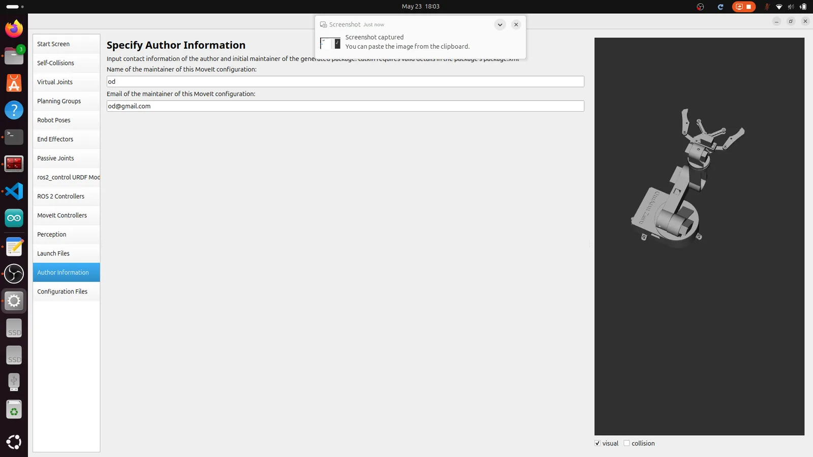
Click Author Information. Enter your name and email. This gets written into package.xml as the package maintainer.
Step 14: Generate the Package
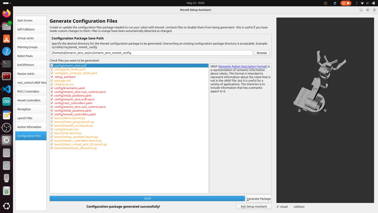
Click Configuration Files. Set the output path:
~/omarm_zero_ws/src/omarm_zero_moveit_config
Click Generate Package. The assistant creates the entire omarm_zero_moveit_config package with all config files, launch files, and CMakeLists.txt. You should see a green “Configuration package generated successfully!” message at the bottom.
Rebuild the workspace:
cd ~/omarm_zero_ws
colcon build
source install/setup.bash
6. Understanding the config files
The Setup Assistant generated a bunch of YAML files. Let’s walk through what each one does, because you’ll need to understand them when things don’t work.
SRDF: the semantic robot description
The SRDF (omarm_zero.srdf) is the companion to the URDF. While the URDF describes the physical structure (links, joints, geometry), the SRDF describes the semantic structure: what groups exist, what collisions to ignore, what named poses are available.
<robot name="omarm_zero">
  <!-- Fixed to the world -->
  <virtual_joint name="world_joint" type="fixed"
                 parent_frame="world" child_link="base_link" />

  <!-- Arm: kinematic chain from base to gripper mount -->
  <group name="arm">
    <chain base_link="base_link" tip_link="gripper_base_1" />
  </group>

  <!-- Gripper: two finger joints -->
  <group name="gripper">
    <joint name="Revolute 6" />
    <joint name="Revolute 7" />
  </group>

  <!-- Gripper is the end effector of the arm -->
  <end_effector name="gripper_eef" parent_link="gripper_base_1"
                group="gripper" parent_group="arm" />

  <!-- Named poses -->
  <group_state name="home" group="arm">
    <joint name="Revolute 1" value="0.8" />
    <joint name="Revolute 2" value="-0.8" />
    <joint name="Revolute 3" value="-1.2" />
    <joint name="Revolute 4" value="-0.8" />
    <joint name="Revolute 5" value="-2.6" />
  </group_state>

  <!-- Collision pairs that can never collide -->
  <disable_collisions link1="base_link" link2="base_link_upper_1"
                      reason="Adjacent" />
  <!-- ... 9 more pairs ... -->
</robot>
kinematics.yaml
Defines which IK solver each planning group uses. The arm group gets KDL. The gripper doesn’t need an IK solver because you control it directly by joint values (open/closed), not by pose.
joint_limits.yaml
Overrides or extends the joint limits from the URDF. MoveIt uses these during planning to keep trajectories within safe bounds.
joint_limits:
  "Revolute 1":
    has_position_limits: true
    min_position: -0.0005    # epsilon below 0
    max_position: 3.14       # pi
    max_velocity: 0.2        # rad/s
    max_acceleration: 0.6    # rad/s^2
  "Revolute 2":
    min_position: -3.14      # -pi
    max_position: 0.0005     # epsilon above 0
    max_velocity: 0.2
    max_acceleration: 0.6
  # ... same pattern for Revolute 3-5
  "Revolute 6":
    min_position: -0.5
    max_position: 0.3
    max_velocity: 0.1        # gripper moves slower
    max_acceleration: 0.3
The small epsilon values (0.0005) at the boundaries prevent the planner from getting stuck exactly at joint limits, which causes numerical issues.
Why are Revolute 2-5 limited to [-pi, 0] while Revolute 1 is [0, pi]? This comes from the URDF joint axis definitions and how the arm was modeled in Fusion 360. The joint axes point in different directions, so the “positive” rotation direction varies.
ompl_planning.yaml
Configures the motion planning algorithms. Three planners are available for the arm:
planner_configs:
  RRTConnectkConfigDefault:
    type: geometric::RRTConnect    # default, fast, bidirectional
  RRTstarkConfigDefault:
    type: geometric::RRTstar       # optimal but slower
  PRMkConfigDefault:
    type: geometric::PRM           # probabilistic roadmap

arm:
  planner_configs:
    - RRTConnectkConfigDefault
    - RRTstarkConfigDefault
    - PRMkConfigDefault
RRTConnect is the default and works well for most scenarios. It grows two random trees (one from start, one from goal) and connects them. Fast but not optimal.
RRTstar finds shorter paths but takes more time. Use it when path quality matters more than planning speed.
PRM builds a roadmap of the configuration space. Slow on the first query but fast on subsequent ones. Good if you’re planning many trajectories in the same environment.
7. Controller configuration
Two config files handle controllers: ros2_controllers.yaml for the actual ros2_control controllers, and moveit_controllers.yaml for MoveIt’s interface to them.
ros2_controllers.yaml
controller_manager:
  ros__parameters:
    update_rate: 100   # Hz

    joint_state_broadcaster:
      type: joint_state_broadcaster/JointStateBroadcaster

    joint_trajectory_controller:
      type: joint_trajectory_controller/JointTrajectoryController

joint_trajectory_controller:
  ros__parameters:
    joints:
      - "Revolute 1"
      - "Revolute 2"
      - "Revolute 3"
      - "Revolute 4"
      - "Revolute 5"
      - "Revolute 6"
      - "Revolute 7"
    command_interfaces:
      - position
    state_interfaces:
      - position
      - velocity
    allow_partial_joints_goal: true
Two controllers run under a single controller_manager:
Joint State Broadcaster reads joint positions and velocities from the hardware interface and publishes them on /joint_states. Every node that needs to know the current arm configuration (RViz, MoveIt, TF2) subscribes to this topic.
Joint Trajectory Controller receives JointTrajectory messages and interpolates between waypoints at 100 Hz, sending position commands to the hardware interface. allow_partial_joints_goal: true means you can send a trajectory for just the arm (5 joints) without including the gripper joints.
moveit_controllers.yaml
moveit_simple_controller_manager:
  controller_names:
    - joint_trajectory_controller

  joint_trajectory_controller:
    type: FollowJointTrajectory
    action_ns: follow_joint_trajectory
    default: true
    joints:
      - "Revolute 1"
      - "Revolute 2"
      - "Revolute 3"
      - "Revolute 4"
      - "Revolute 5"
      - "Revolute 6"
      - "Revolute 7"
This tells MoveIt how to reach the controller. MoveIt sends a FollowJointTrajectory action goal to /joint_trajectory_controller/follow_joint_trajectory. The controller executes the trajectory and sends back a result (success/failure).

8. Gripper and mimic joints
The OmArm Zero gripper has two fingers, each driven by its own servo. In the URDF, these are Revolute 6 (left finger) and Revolute 7 (right finger). But you never want to move them independently. When the gripper closes, both fingers move symmetrically.
This is a mimic joint pattern. You command one joint and the other follows. In the SRDF, both joints are in the “gripper” planning group. When you send a gripper command (e.g., “closed”), both joints get the same value (-0.35 rad).
In Part 2, we built a gripper_mimic_bridge node that subscribes to one finger’s command and mirrors it to the other. For MoveIt, the setup is simpler: the named poses (“open” and “closed”) specify both joints, and the trajectory controller moves them together.
<!-- Both fingers get the same value -->
<group_state name="closed" group="gripper">
  <joint name="Revolute 6" value="-0.35" />
  <joint name="Revolute 7" value="-0.35" />
</group_state>
Why not use a real URDF mimic joint? Because Gazebo and ros2_control handle mimic joints inconsistently across versions. Explicitly controlling both joints is more reliable and easier to debug.
9. MoveIt demo: mock hardware
Time for the first hands-on moment. The MoveIt demo launches the full planning pipeline with mock hardware. No Gazebo, no real robot. The mock hardware pretends to have motors and mirrors back whatever position it’s told to go to. This is the fastest way to verify your MoveIt configuration.
Launch the demo
cd ~/omarm_zero_ws
source install/setup.bash
ros2 launch omarm_zero_moveit_config demo.launch.py
What happens under the hood
demo.launch.py does something clever: it loads the URDF, then patches the hardware plugin. The URDF specifies gz_ros2_control/GazeboSimSystem (for Gazebo). The demo replaces this with mock_components/GenericSystem, which is a fake hardware interface built into ros2_control. No Gazebo needed.
The launch sequence is ordered with event handlers to ensure everything starts in the right order:
1. robot_state_publisher     (loads URDF, publishes TF)
2. ros2_control_node         (manages hardware interface)
3. joint_state_broadcaster   (waits for ros2_control, then publishes /joint_states)
4. joint_trajectory_controller (waits for JSB, then accepts trajectories)
5. move_group + RViz         (waits for controller, then starts planning)
Each step waits for the previous one to finish before starting. This prevents race conditions where MoveIt tries to plan before the controller is ready.
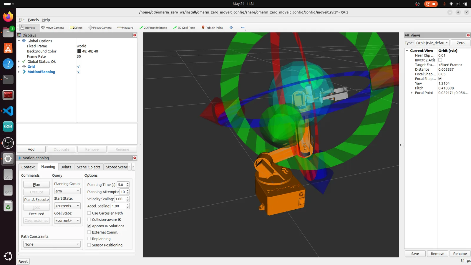
Your first motion plan
In RViz, you’ll see the robot with an interactive marker on the gripper. The orange arm is the goal state. The green arm (when visible) shows the planned trajectory.
- Drag the orange ball on the gripper to a new position
- In the MotionPlanning panel, click Plan
- Watch the green trajectory appear
- Click Execute to move the mock arm to the goal
- The arm snaps to the new position (no physics, instant movement)
Try the named poses
In the MotionPlanning panel under Planning, find the dropdown for “Goal State.” Select home, then Plan & Execute. Try open و closed for the gripper (switch to the “gripper” planning group first).
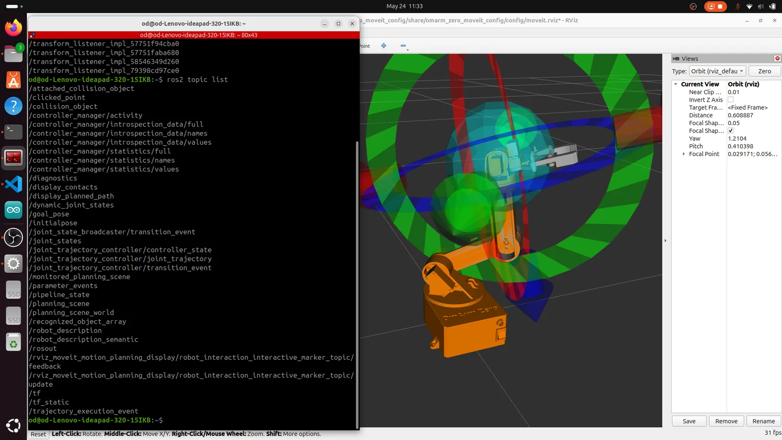
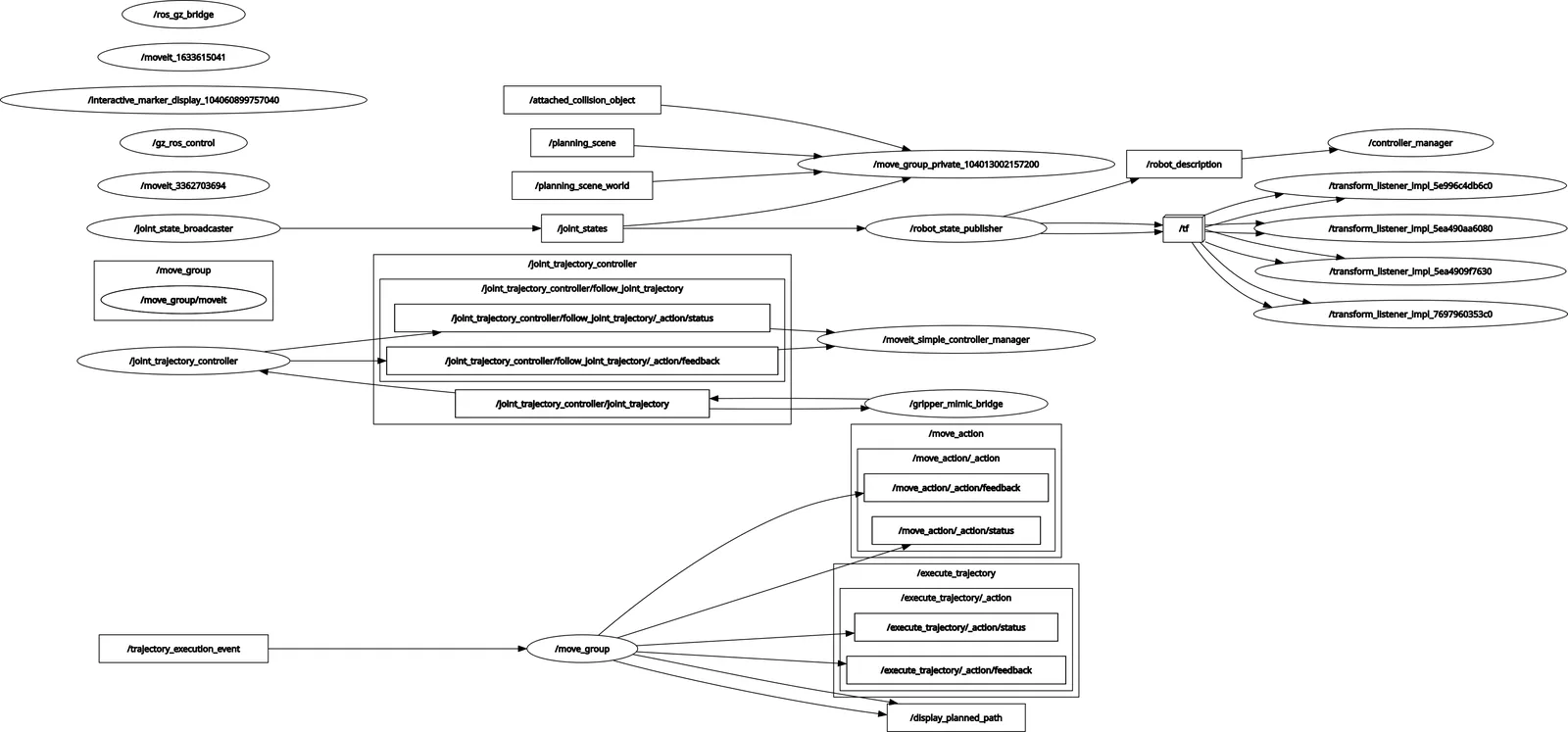
Inspect the ROS 2 graph
Open a new terminal and run:
ros2 node list
ros2 topic list
rqt_graph
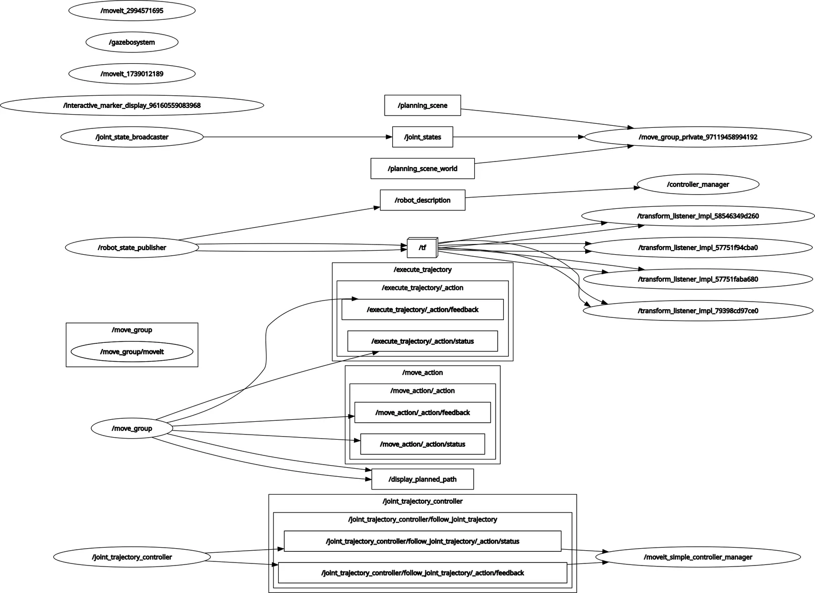
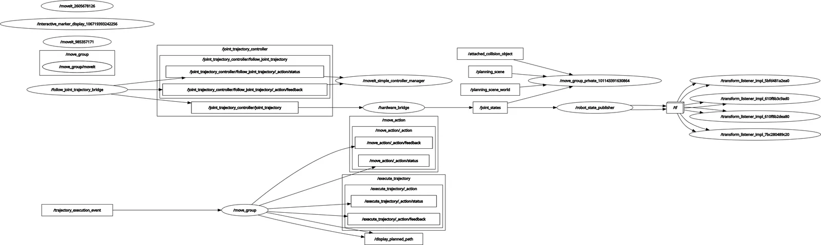
The graph shows how everything connects:
move_group← sends trajectory to →joint_trajectory_controllerjoint_trajectory_controller← reads state from →ros2_control_nodejoint_state_broadcaster→ publishes →/joint_statesrobot_state_publisher← subscribes →/joint_states, publishes →/tfrviz2← subscribes →/tf,/joint_states, planning scene
This is the same architecture that runs on real hardware. Only the hardware interface changes.
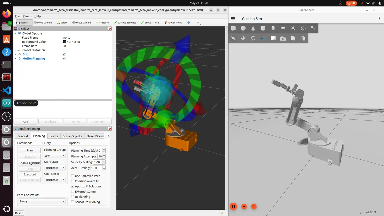
10. MoveIt + Gazebo simulation
The demo uses mock hardware. For actual physics (gravity, inertia, contact), launch MoveIt on top of the Gazebo simulation from Part 2.
Launch MoveIt with Gazebo
ros2 launch omarm_zero_moveit_config gazebo_moveit.launch.py
This launch file does three things in sequence:
- t=0s: Launches the Gazebo simulation (from
omarm_zero_description/gazebo.launch.py) - t=4s: Starts
move_groupمعuse_sim_time: true - t=8s: Opens RViz with MoveIt plugin
The delays ensure Gazebo is fully loaded before MoveIt connects. Without them, MoveIt would try to read joint states from a simulation that hasn’t spawned the robot yet.
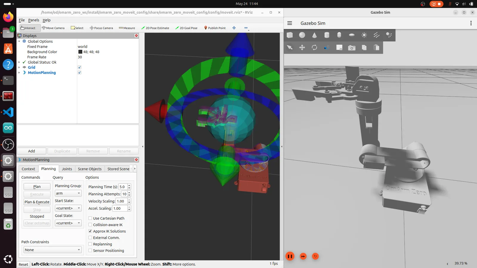
Differences from the demo
The key difference: physics. In the demo, the arm teleports to its goal. In Gazebo, it accelerates, moves, and decelerates according to the planned trajectory. You can see the difference most clearly with longer moves. Plan a large motion and watch the arm smoothly follow the trajectory in the Gazebo window.
Gravity is now a factor. If you disable the controllers, the arm would collapse under its own weight. The JointTrajectoryController actively holds position even when no trajectory is being executed.
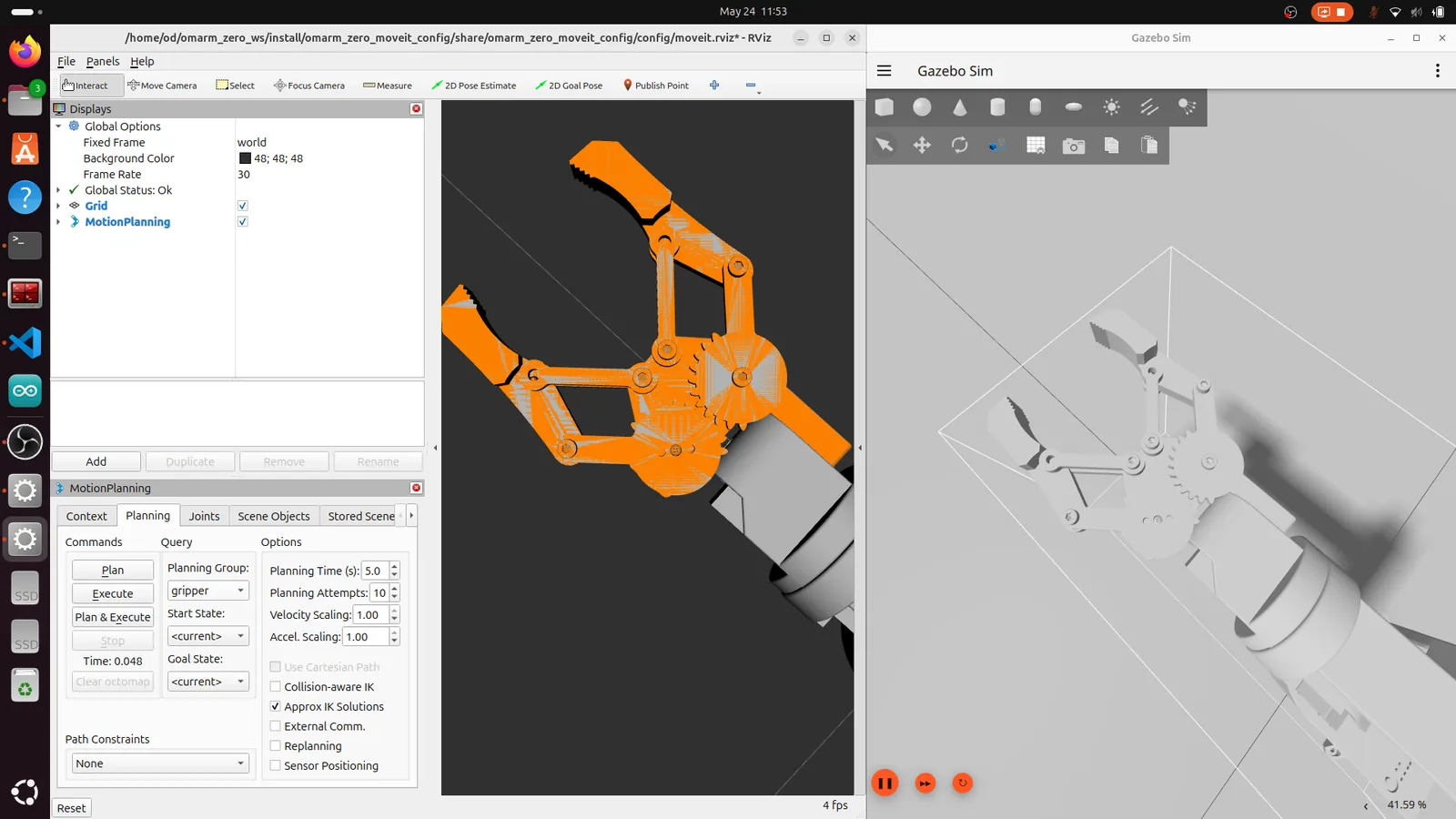
Plan and execute in Gazebo
The workflow is identical to the demo:
- Drag the interactive marker or select a named pose
- Click Plan to see the trajectory
- Click Execute to watch the arm move in both RViz and Gazebo simultaneously
Switch to the gripper planning group to test open/close. Select “closed” or “open” as the goal state and execute.
If a plan fails, check the terminal output. Common issues: the goal is outside the joint limits, the arm would collide with itself, or the solver can’t find a solution within the timeout.
The full ROS 2 graph with Gazebo running is more complex than the demo. The ros_gz_bridge node bridges between Gazebo and ROS 2, and gz_ros_control manages the simulated hardware interface.
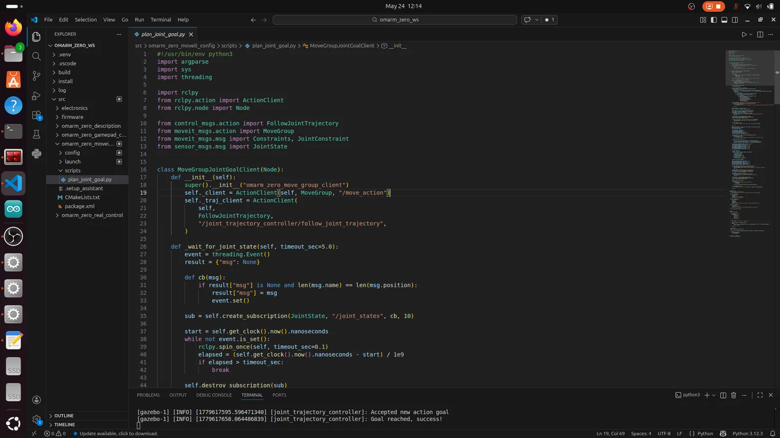
11. MoveIt Python API: scripting motion
The RViz interface is great for testing, but for automation you need code. The plan_joint_goal.py script in the omarm_zero_moveit_config package shows how to send goals programmatically.
Usage
# Plan only (don't execute)
ros2 run omarm_zero_moveit_config plan_joint_goal.py \
    --group arm --target 1.0 -1.0 -1.5 -0.8 -2.0

# Plan and execute
ros2 run omarm_zero_moveit_config plan_joint_goal.py \
    --group arm --target 1.0 -1.0 -1.5 -0.8 -2.0 --execute

# Close the gripper
ros2 run omarm_zero_moveit_config plan_joint_goal.py \
    --group gripper --target 0.1 0.1 --execute

# Open the gripper
ros2 run omarm_zero_moveit_config plan_joint_goal.py \
    --group gripper --target -0.35 -0.35 --execute
The arm group expects 5 values (Revolute 1-5), the gripper group expects 2 (Revolute 6-7).
كيف تعمل
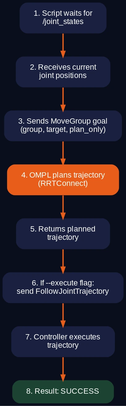
The script uses the MoveGroup action, which is MoveIt’s primary interface. Here’s the flow:
1. Wait for /joint_states to get the current arm configuration
2. Build a MoveGroup goal with:
   - Planning group name ("arm" or "gripper")
   - Current state as start state
   - Target joint values as goal constraints
   - Planning parameters (attempts, time, velocity scaling)
3. Send goal to /move_action (MoveGroup action server)
4. MoveIt plans the trajectory (plan_only: true)
5. If --execute: send the planned trajectory to
   /joint_trajectory_controller/follow_joint_trajectory
6. Wait for execution result
Key parameters in the script
req.num_planning_attempts = 5          # try 5 times if planning fails
req.allowed_planning_time = 8.0        # seconds
req.max_velocity_scaling_factor = 0.2  # 20% of max joint velocity
req.max_acceleration_scaling_factor = 0.2
The velocity and acceleration scaling factors are important for real hardware. At 100% the servos would try to move at their maximum speed, which can cause the arm to shake or overshoot. 20% gives smooth, controlled motion.
Extending the script
plan_joint_goal.py sends joint-space goals. For Cartesian goals (move the gripper to XYZ), you would use moveit_commander أو MoveGroupInterface C++ API. That’s beyond the scope of this tutorial, but the architecture is the same: goal → plan → execute.
12. Bridge architecture: MoveIt to real hardware
This is the most interesting part of the whole setup. How do you get a trajectory planned by MoveIt on your Linux PC to move physical servos on an ESP32 microcontroller?
The standard approach in ROS 2 is to write a ros2_control hardware interface plugin in C++. That’s a lot of boilerplate for hobby servos connected over serial. The OmArm Zero uses a simpler approach: a pure-Python bridge that fakes the ros2_control interface.
The bridge nodes
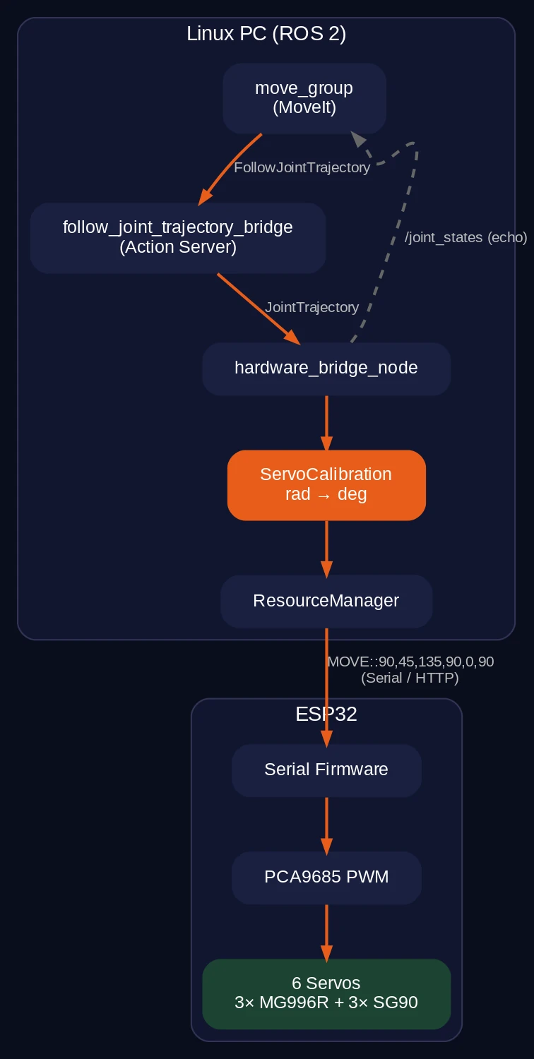
Two Python nodes replace the entire ros2_control stack for real hardware:
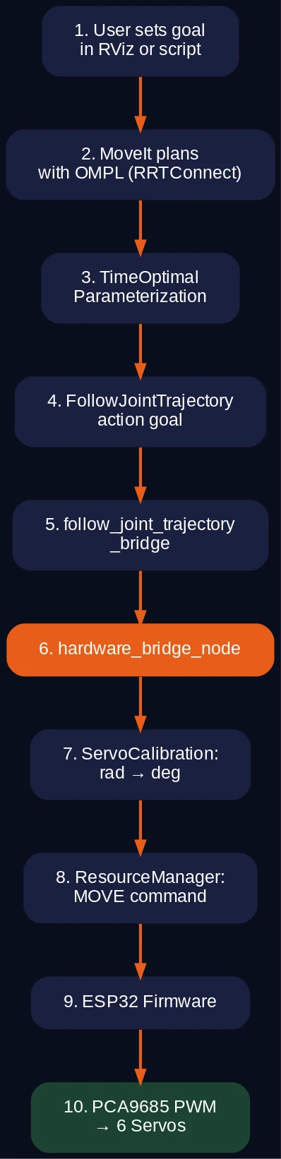
follow_joint_trajectory_bridge is an action server that pretends to be a JointTrajectoryController. MoveIt sends FollowJointTrajectory goals to it. The bridge accepts the goal, publishes the trajectory on a topic, waits for the estimated execution time, and reports success.
MoveIt → FollowJointTrajectory action goal
       → follow_joint_trajectory_bridge (action server)
       → publishes JointTrajectory on /joint_trajectory_controller/joint_trajectory
hardware_bridge_node subscribes to the trajectory topic, takes the last waypoint, converts joint angles from radians to servo degrees, and sends a MOVE command to the ESP32.
/joint_trajectory_controller/joint_trajectory
       → hardware_bridge_node
       → ServoCalibration: radians → degrees
       → ResourceManager: "MOVE:90,45,135,90,0,90"
       → ESP32 (serial or HTTP)
The hardware bridge also publishes echo state on /joint_states at 50 Hz. This is open-loop: it publishes what it commanded, not what the servos actually did. There are no encoders on the OmArm Zero’s hobby servos, so this is the best we can do.
Why a bridge instead of ros2_control?
A proper ros2_control hardware interface would be more correct. But it requires C++, a custom plugin, a compiled library, and a non-trivial amount of infrastructure code. The Python bridge:
- Works identically from MoveIt’s perspective (same action interface)
- Is easier to modify and debug (Python, not C++)
- Handles the ESP32’s command protocol directly (serial strings, HTTP JSON)
- Can be understood and modified by students and hobbyists
The tradeoff: no real-time guarantees, no encoder feedback, no closed-loop position control. For hobby servos that don’t have encoders anyway, this doesn’t matter.
Transport options
إن ResourceManager supports two transport methods:
Serial: Sends MOVE:a1,a2,a3,a4,a5,a6\n at 115200 baud to /dev/ttyUSB0. The ESP32 reads the string, parses the angles, and drives the servos.
HTTP: Posts JSON {"cmd": "MOVE:a1,a2,a3,a4,a5,a6"} to http://10.10.10.1/api/command. This uses the ESP32’s WiFi access point from Part 1. Useful when the USB cable is inconvenient.
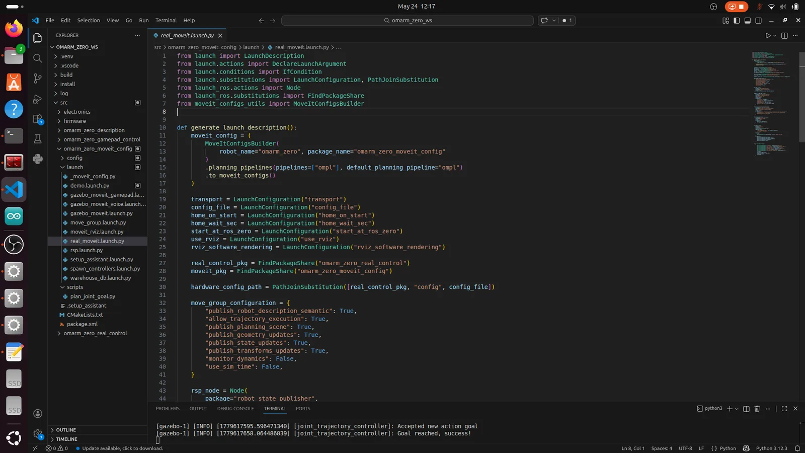
# Launch with serial transport (default)
ros2 launch omarm_zero_moveit_config real_moveit.launch.py transport:=serial

# Launch with HTTP transport
ros2 launch omarm_zero_moveit_config real_moveit.launch.py transport:=http
13. Servo calibration
The bridge converts joint angles from radians (what MoveIt uses) to servo degrees (what the ESP32 expects). This conversion is not trivial because the servo zero position doesn’t match the URDF zero position.
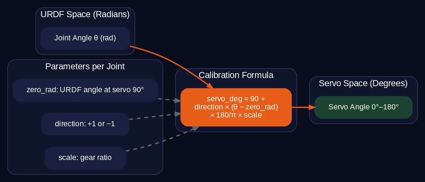
The calibration formula
servo_deg = 90 + direction * (joint_rad - zero_rad) * (180/pi) * scale
Each joint has four calibration parameters:
| المعلمة | Meaning |
|---|---|
zero_rad |
The URDF joint angle where the servo should be at its zero position |
direction |
+1 or -1, because some servos are mounted backwards |
scale |
Usually 1.0, but can compensate for gear ratios |
| Clamping | Output is clamped to [0, 180] degrees |
Default calibration values
# hardware.yaml
joints:
  - name: "Revolute 1"
    servo_type: MG996R
    channel: 0
    zero_rad: 1.5708    # pi/2
    direction: 1
    scale: 1.0
  - name: "Revolute 2"
    servo_type: MG996R
    channel: 3
    zero_rad: -1.5708   # -pi/2
    direction: 1
    scale: 1.0
  # ... pattern continues for joints 3-6
Why zero_rad matters
In the URDF, the “zero” position of each joint depends on how the CAD model was assembled. Revolute 1 (base rotation) has its zero at 0 rad in the URDF, but the physical servo needs to be at 90 degrees (straight ahead). So zero_rad = pi/2: when the URDF angle is pi/2, the servo goes to 90 degrees.
For Revolute 2-5, the URDF zero is at -pi/2 (the arm is folded). The physical servo at -pi/2 should be at 90 degrees. So zero_rad = -pi/2.
Adjusting calibration
If the real arm doesn’t match the RViz visualization:
- Launch
real_moveit.launch.py - Set the arm to the “home” pose in RViz
- Compare the real arm position with RViz
- If a joint is offset, adjust its
zero_radinhardware.yaml - Restart the launch file
Small offsets (under 5 degrees) are normal due to servo manufacturing tolerances and 3D-printed part fit.
14. Real robot launch: everything together
This is the payoff. MoveIt plans a trajectory on your PC, the bridge converts it to servo commands, and the real arm moves.
Prerequisites
- ESP32 connected via USB (or WiFi for HTTP transport)
- ESP32 flashed with
omarm_zero_ros2_serial.inofirmware - Servos powered (separate 5V supply, not USB power)
Flash the firmware
مفتوح omarm_zero_ros2_serial.ino in Arduino IDE, select your ESP32 board, and upload. The firmware supports these commands over serial at 115200 baud:
STATUS          → returns JSON with current servo positions
HOME / ZERO     → all servos to 0 degrees
MOVE:a1,...,a6  → set target angles (0-180)
SPEED:n         → movement speed (1-20)
Test the connection:
# Check the serial port
ls /dev/ttyUSB*

# Send a test command (install screen if needed)
screen /dev/ttyUSB0 115200
# Type: STATUS
# Expected: {"status":"ok","pos":[0,0,0,0,0,0]}
# Exit screen: Ctrl-A, then K, then Y
Launch MoveIt with real hardware
ros2 launch omarm_zero_moveit_config real_moveit.launch.py
The launch file starts:
robot_state_publisher(URDF → TF)hardware_bridge_node(serial/HTTP bridge to ESP32)follow_joint_trajectory_bridge(action server for MoveIt)move_group(MoveIt planning)rviz2(visualization)
If home_on_start is true (default), the arm moves to its home position immediately after startup. Wait for it to settle before planning.
The ROS 2 graph for real hardware replaces Gazebo’s gz_ros_control with the Python bridge nodes. The follow_joint_trajectory_bridge acts as the action server, and hardware_bridge handles serial communication.
Plan and execute on the real arm
The workflow is the same as the demo and Gazebo:
- Drag the interactive marker in RViz
- Click Plan to see the trajectory
- Click Execute to move the real arm
The arm moves incrementally (the ESP32 firmware steps at 80ms intervals) rather than following the exact trajectory timing. This means the motion is smoother than a direct jump but not perfectly time-synchronized with the plan. For hobby servos without encoder feedback, this is the expected behavior.
Launch parameters
# All available parameters
ros2 launch omarm_zero_moveit_config real_moveit.launch.py \
    transport:=serial \          # serial or http
    config_file:=hardware.yaml \ # calibration config
    home_on_start:=true \        # move to home on startup
    home_wait_sec:=1.5 \         # wait time after homing
    start_at_ros_zero:=false \   # start at ROS zero instead of home
    use_rviz:=true               # launch RViz
Using the Python API with real hardware
إن plan_joint_goal.py script works identically with real hardware:
# Move the real arm to a target
ros2 run omarm_zero_moveit_config plan_joint_goal.py \
    --group arm --target 1.2 -0.5 -1.0 -1.5 -2.0 --execute

# Open the gripper
ros2 run omarm_zero_moveit_config plan_joint_goal.py \
    --group gripper --target 0.1 0.1 --execute
The same trajectory goes through the same MoveIt pipeline. Only the endpoint changes: instead of a simulated controller, the trajectory reaches the bridge, gets converted to servo commands, and drives the physical arm.
استكشاف الأخطاء وإصلاحها
Arm doesn’t move: Check ls /dev/ttyUSB*. Try screen /dev/ttyUSB0 115200 and send STATUS. If no response, check USB cable and ESP32 power.
Arm moves but wrong direction: يُعدِّل direction in hardware.yaml for the affected joint. Change from 1 to -1 or vice versa.
Arm position doesn’t match RViz: يُعدِّل zero_rad for the mismatched joint. Small offsets are normal.
Planning fails: Check that joint limits in joint_limits.yaml match the physical arm’s range. If the goal is near a joint limit, the planner may not find a valid path.
Jerky motion: Reduce max_velocity_scaling_factor in the planning request. The default 0.2 (20%) should be smooth. Also check the ESP32 SPEED setting.
MoveIt Setup Assistant crashes: Make sure the URDF loads cleanly with check_urdf. If the URDF has Xacro includes, run xacro first and pass the generated URDF to the assistant.
Controller not found: Run ros2 control list_controllers. If the list is empty, the controller manager hasn’t started. Check the launch file and verify that ros2_control parameters are loaded correctly.
الأسئلة المتداولة
What is MoveIt 2?
MoveIt 2 is the motion planning framework for ROS 2. It takes a target pose for your robot’s end-effector, solves the inverse kinematics to find valid joint angles, then plans a collision-free trajectory to get there. It handles the math so you can think in terms of “move the gripper here” instead of manually setting each joint angle.
Do I need a powerful computer for MoveIt 2?
Not for a 6-DOF arm like the OmArm Zero. Planning takes under a second on most modern laptops. Gazebo simulation is the heavier part. 8 GB RAM and any multi-core CPU from the last five years will work fine.
Can I use MoveIt 2 without Gazebo?
Yes. MoveIt includes mock hardware interfaces for testing motion planning without any simulation. You can plan and visualize trajectories entirely in RViz. Gazebo adds physics simulation but is not required for motion planning itself.
How does the real hardware bridge work?
The bridge node subscribes to the FollowJointTrajectory action that MoveIt sends, converts each trajectory point from radians to servo degrees using a calibration formula, and sends the result to the ESP32 over serial USB. The ESP32 firmware drives the PCA9685 PWM controller, which moves the servos.
Why does my arm move to the wrong position?
Usually a calibration issue. The zero_rad و direction parameters in hardware.yaml map the software’s joint angles to physical servo positions. If one joint is off, adjust its zero_rad value. If a joint moves backwards, flip its direction from 1 to -1.
Can I use this with a different robot arm?
Yes, but you’ll need your own URDF and calibration parameters. The MoveIt configuration (Setup Assistant, controllers, launch files) follows the same pattern for any robot. The hardware bridge is specific to ESP32 + PCA9685 servos but can be adapted to other microcontrollers.
What comes next
Part 3 covered the full pipeline from motion planning to real robot control. The OmArm Zero can now plan collision-free trajectories and execute them on both simulation and hardware.
In Part 4, we’ll add eyes. Computer vision with a camera, object detection, and autonomous pick-and-place. The arm won’t just go where you tell it. It’ll decide where to go on its own.