

At a glance
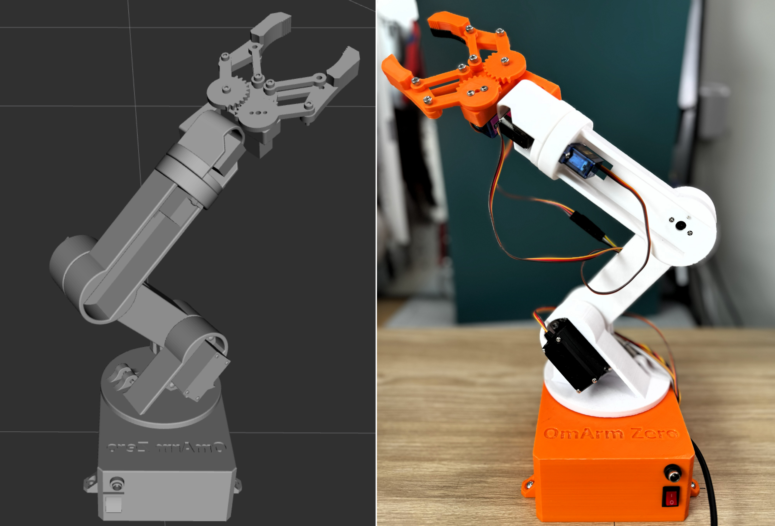
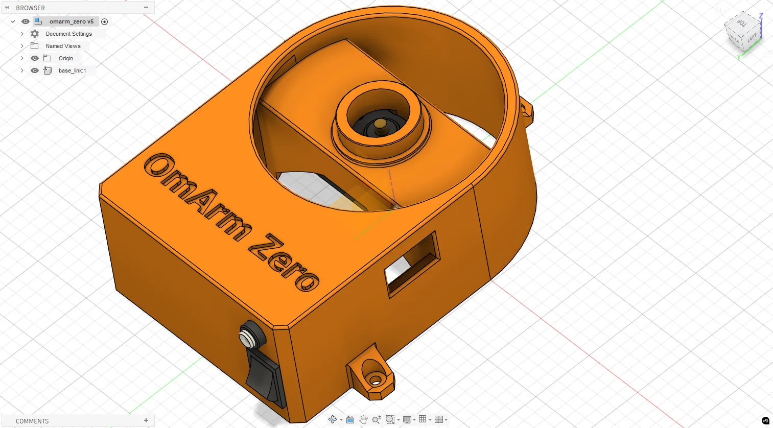
What you’ll build: A complete digital twin of a 6-DOF robot arm (the OmArm Zero) using URDF/Xacro, RViz, and Gazebo Harmonic. You’ll go from an empty workspace to a simulated arm that responds to joint trajectory commands with full physics.
Prerequisites: Any URDF-compatible robot arm or the OmArm Zero from Part 1. Basic terminal skills. No prior ROS experience needed.
Software: Ubuntu 22.04, ROS 2 Jazzy, Gazebo Harmonic, RViz2
Time: 2-4 hours (setup + inevitable debugging)
Difficulty: Intermediate. You’ll edit XML, run launch files, and debug joint configurations until something finally lines up.
Files: Full ROS 2 workspace on GitHub (link at the end)
Table of contents
- Why a digital twin?
- ROS 2 building blocks: a kitchen analogy
- Packages and workspaces: organizing the kitchen
- TF2: coordinate transforms
- Setting up the environment
- URDF and Xacro: describing your robot
- Creating the URDF: manual workflow and Fusion 360 export
- Visualizing in RViz
- Simulating in Gazebo
- ros2_control: the control architecture
- The gripper mimic bridge
- Launch files that tie it all together
- Testing and validation
- What comes next
1. Why a digital twin?
In Part 1 I built the OmArm Zero, wired it up, wrote the firmware, and controlled it from a web browser. That works. But here’s what kept happening: I’d write a new motion sequence, run it on the real arm, and watch it slam into the desk. Or into itself. I stripped three servo horns this way before I got fed up.
A digital twin fixes that. It’s the arm, but on your screen. You can crash it all day and nothing breaks. No cracked PLA, no stripped gears, no noise at 2am waking up the house.
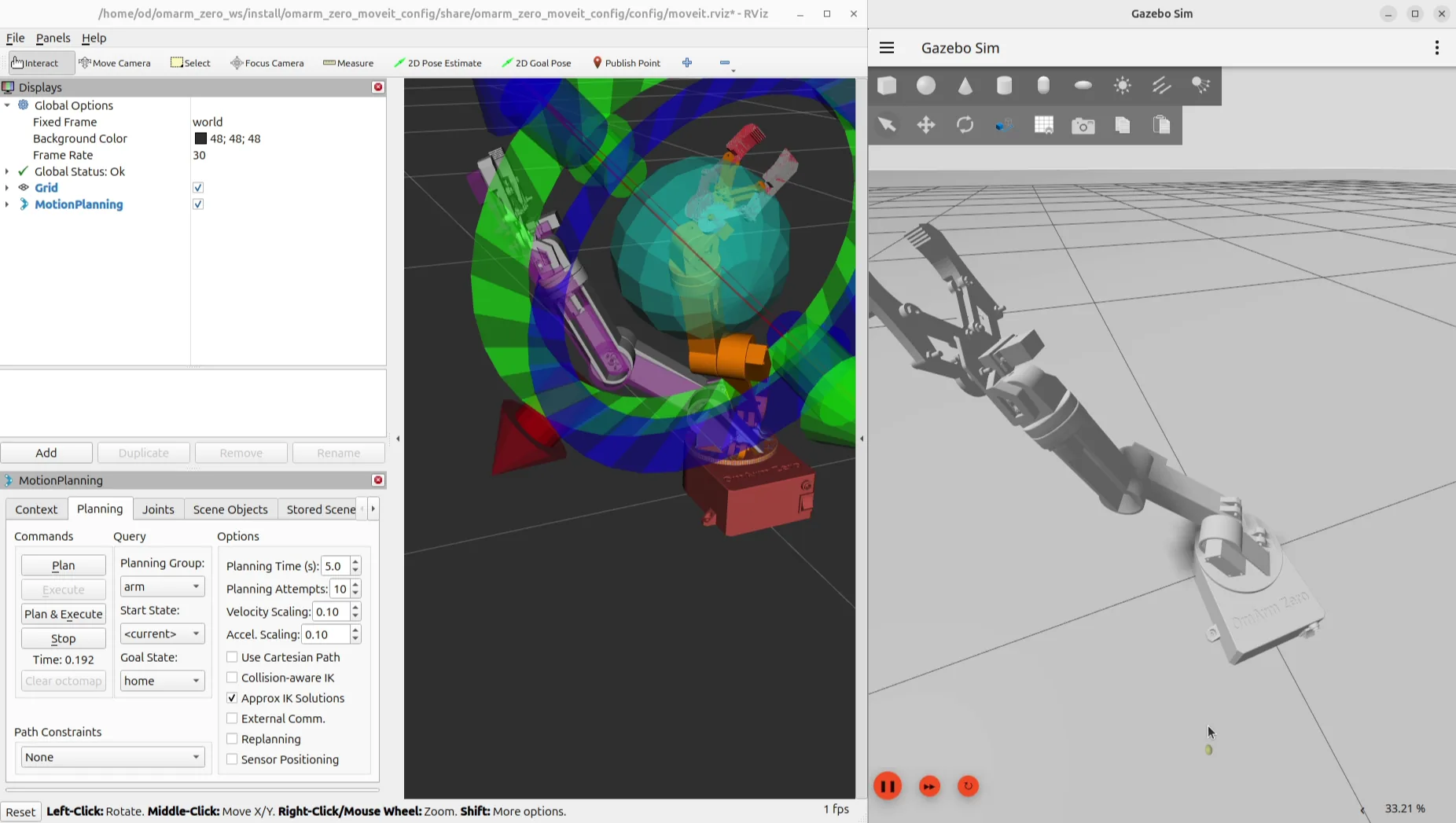
That alone would be worth it, but the real payoff is deeper. I can see the coordinate frame of every joint, inspect the full transform tree, test inverse kinematics, verify that a trajectory stays within torque limits. All without powering a single servo. When MoveIt plans a path in Part 3, this simulated arm is what it plans against.
ROS 2 ties everything together. If you’ve never touched it, the next three sections cover the core concepts before we install anything. Already familiar with nodes, topics, and launch files? Jump to Section 5.
2. ROS 2 building blocks: a kitchen analogy
Hands-on learner? Sections 2-4 are background theory. Skip to Section 5 and come back when you hit a term you don’t recognize. Seriously, it’s fine. I won’t judge.
The ROS 2 vocabulary (nodes, topics, messages, services, actions, parameters, launch files) sounds like a lot. It’s not. Each piece is simple. They just have bad names.
I’ll use a restaurant kitchen as a running analogy because it maps surprisingly well and it made things click for me when I was learning this.
Nodes: kitchen stations
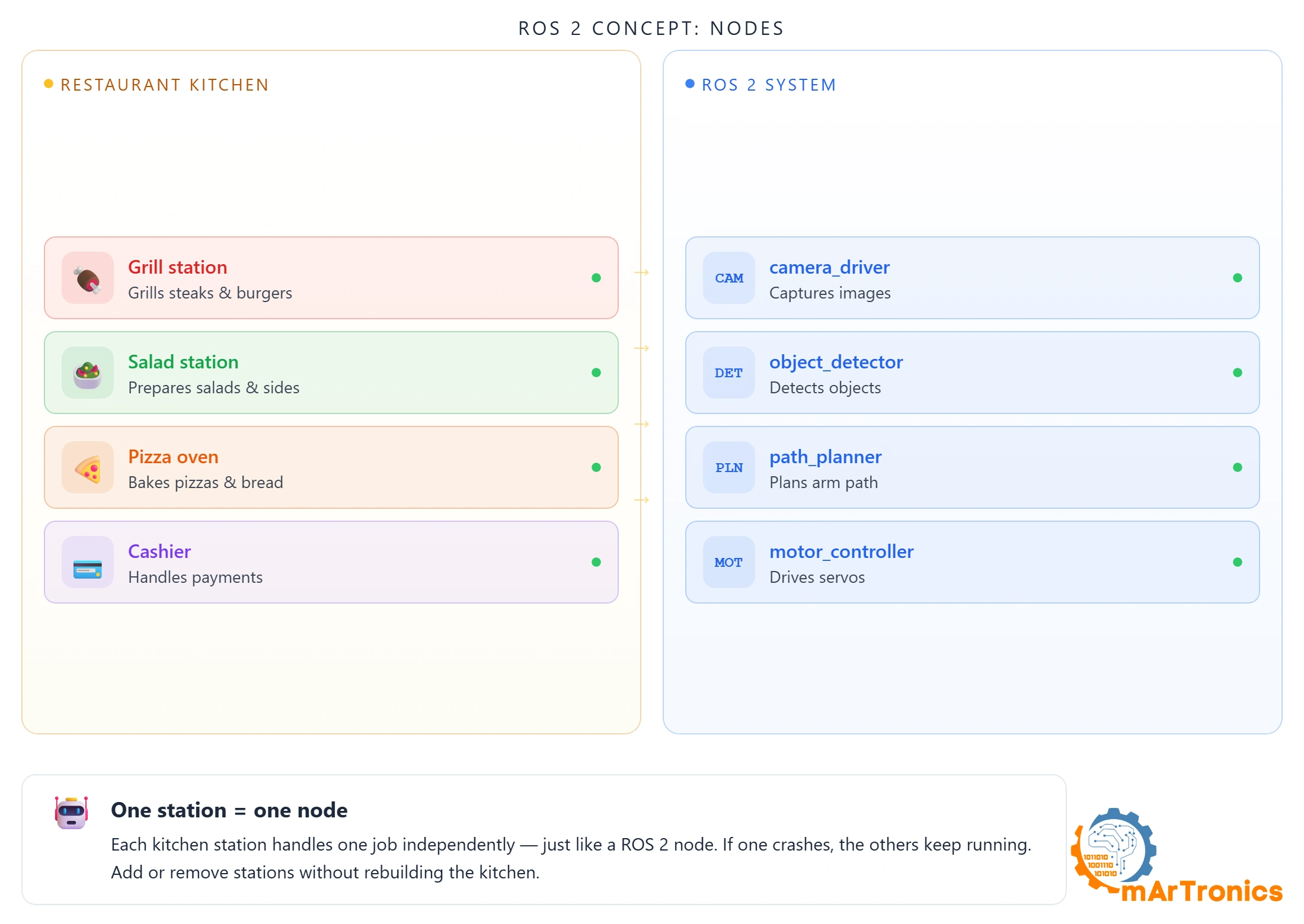
A kitchen has stations: grill, salad, pizza oven. Each one does one job, runs independently, has its own chef. If the grill chef takes a break, salads keep going out.
A ROS 2 node is a station. One program, one job. camera_driver captures images. object_detector finds objects. motor_controller drives motors. If one crashes, the rest keep running. You can swap any node without touching the others.
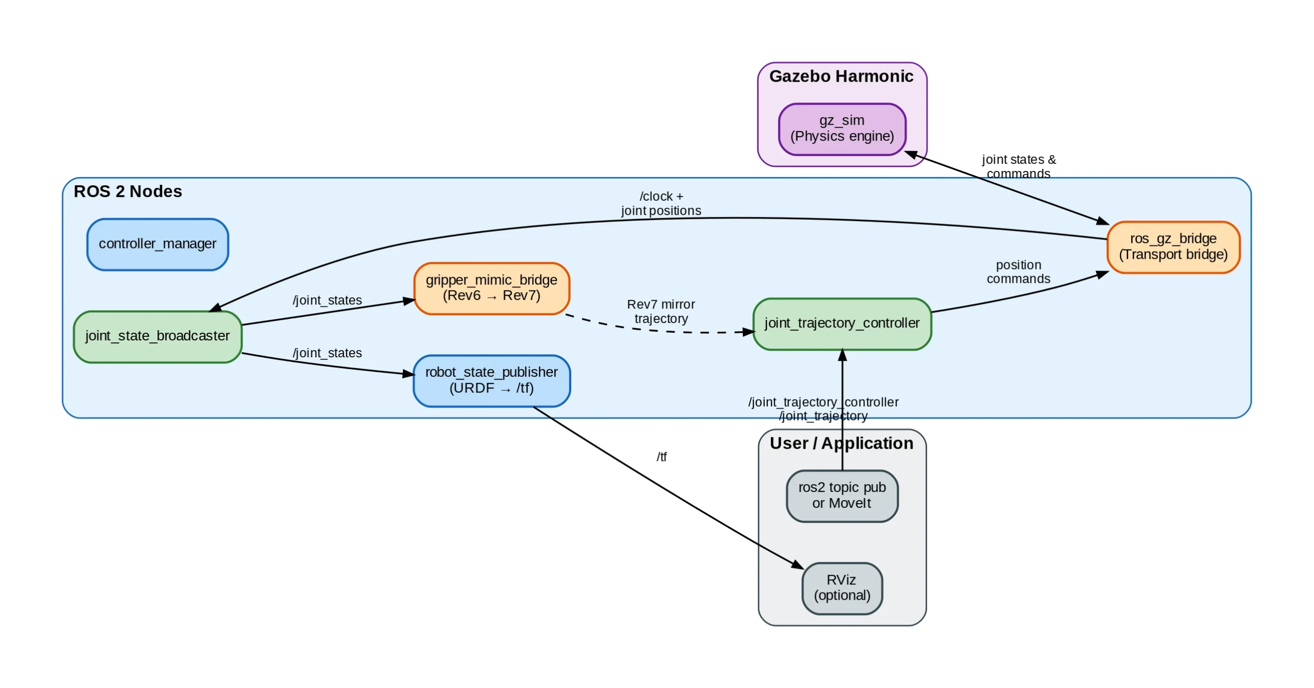
OmArm Zero runs 5 nodes: robot_state_publisher, joint_state_broadcaster, rviz2, controller_managerو gripper_mimic_bridge. See them with ros2 node list.
Topics and publish/subscribe: the kitchen whiteboard
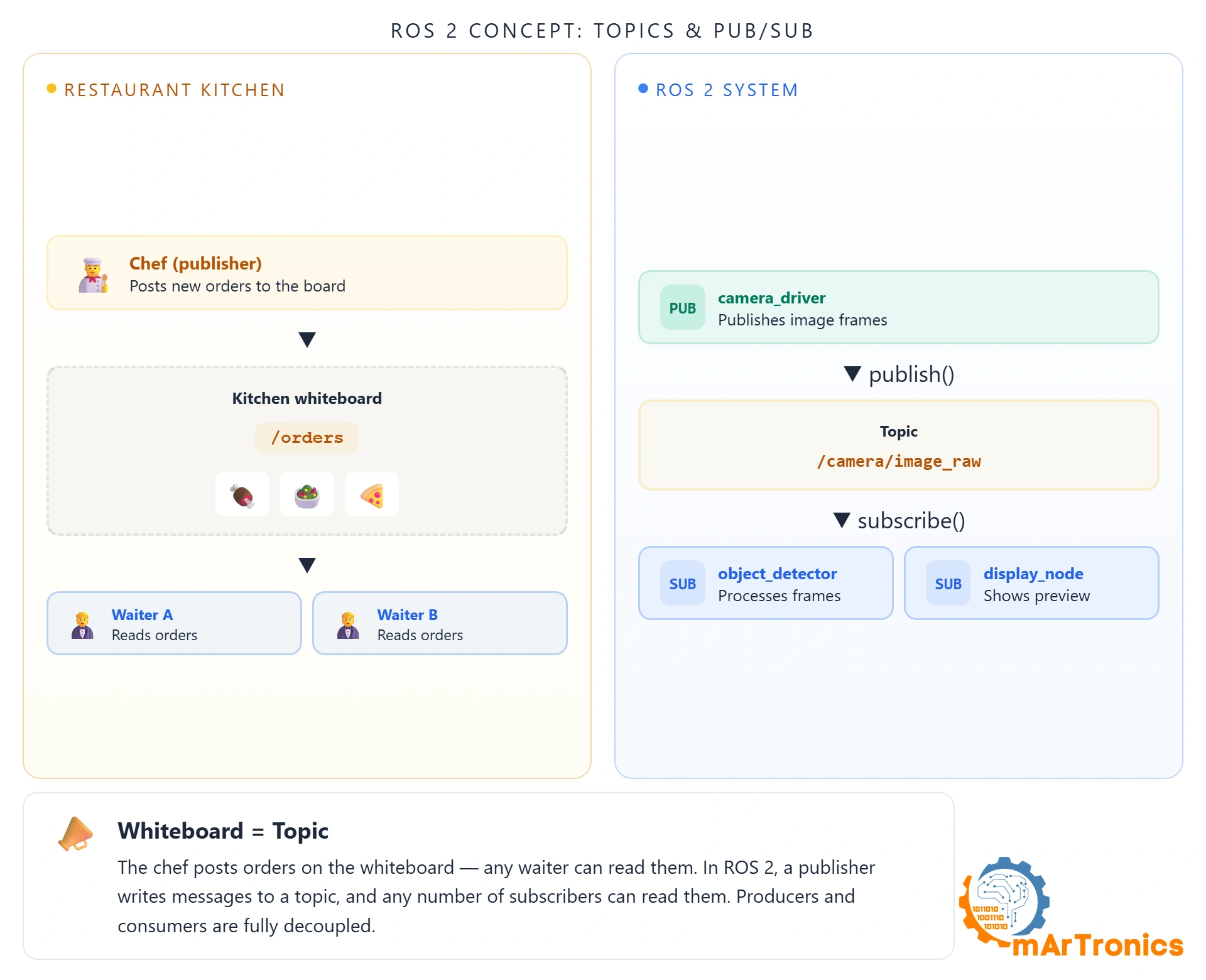
The kitchen whiteboard: the chef writes “Table 5 steak ready” and everyone can read it. Nobody erases it. Everyone sees it at the same time.
That’s a ROS 2 topic. A node publishes data to a named channel, and any number of other nodes can subscribe. The publisher doesn’t know or care who’s listening. This isn’t a queue where one consumer takes the message. It’s broadcast. Three subscribers to /camera/image means three copies of every frame.
OmArm Zero’s key topics: /joint_states (current angles of all 7 joints), /tf (coordinate transforms), /joint_trajectory_controller/joint_trajectory (motion commands).
Messages: order slips with a fixed format
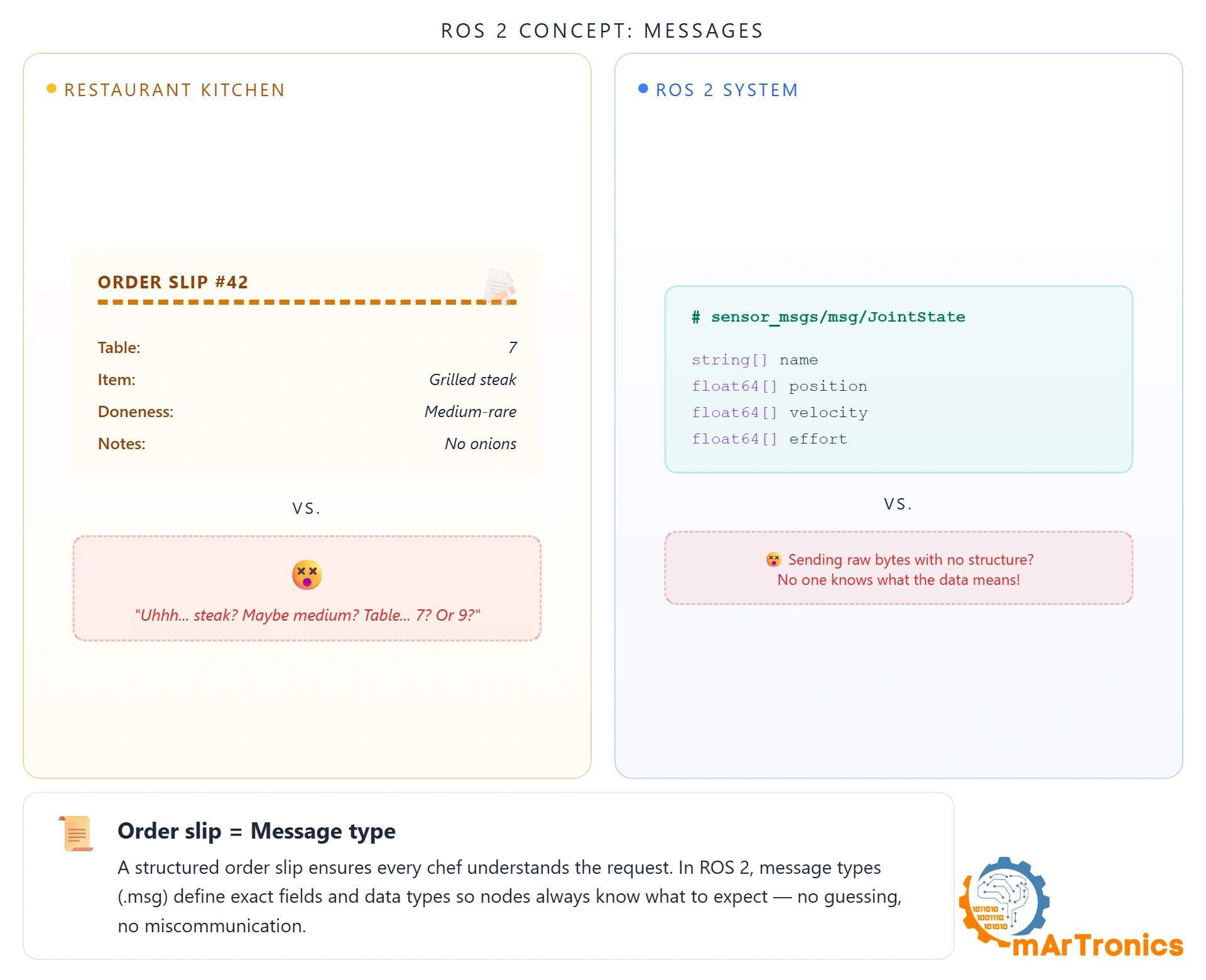
A waiter scribbling “steak for the window guy, medium-ish” on a napkin is asking for trouble. A proper order slip has fixed fields: table number, dish, doneness, sides. No ambiguity.
ROS 2 messages work the same way. Every message has typed fields. sensor_msgs/JointState contains string[] name, float64[] position, float64[] velocity, float64[] effort. Every node that reads it knows exactly what to expect.
Inspect any message type with ros2 interface show sensor_msgs/msg/JointState. Watch them flow live with ros2 topic echo /joint_states.
Services: asking the kitchen a question
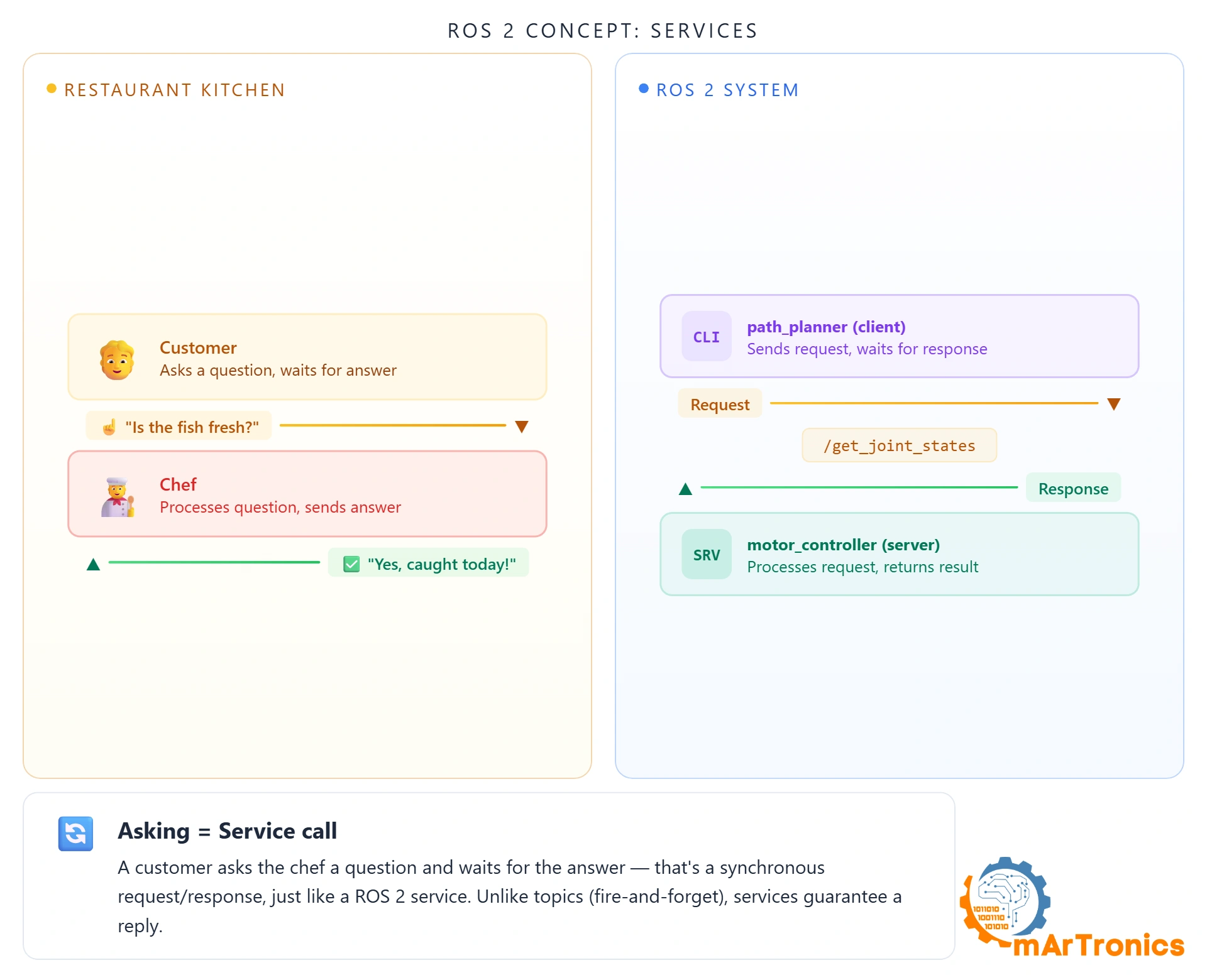
“Is the fish fresh today?” You ask, you wait, you get one answer. That’s it. No ongoing stream. The customer blocks until the waiter comes back.
A ROS 2 service works identically. One request, one response, client blocks until it arrives. The opposite of topics. Use topics for continuous data (sensor streams, joint states). Use services for one-shot operations (spawn a model, switch a controller).
OmArm Zero uses services to spawn the robot in Gazebo (/spawn_entity) and switch controllers (/controller_manager/switch_controller).
Actions: ordering a steak
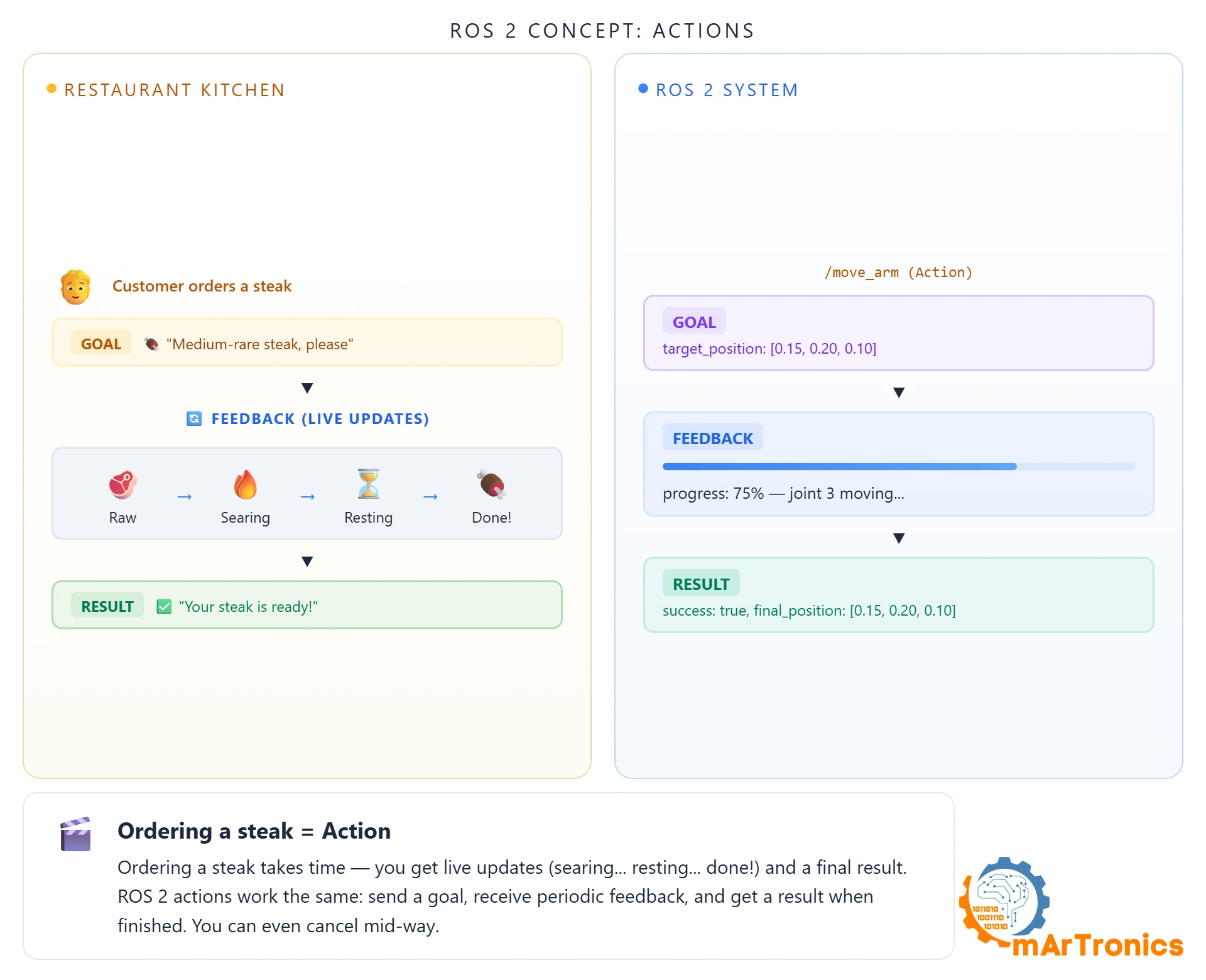
What if a task takes a long time? A service would block the entire time. That’s like ordering a well-done steak and the waiter vanishing for 25 minutes with zero updates.
An action gives you progress. You send a goal, get periodic feedback (“searing”, “flipping”, “resting”), and finally a result. You can also cancel halfway through if you change your mind.
Three parts: goal (what you want), feedback (updates while it works), result (succeeded/aborted/canceled). OmArm Zero uses the FollowJointTrajectory action. MoveIt sends a trajectory goal, the controller executes it, sends feedback on joint positions, and reports success when done.
Parameters: adjusting the oven temperature
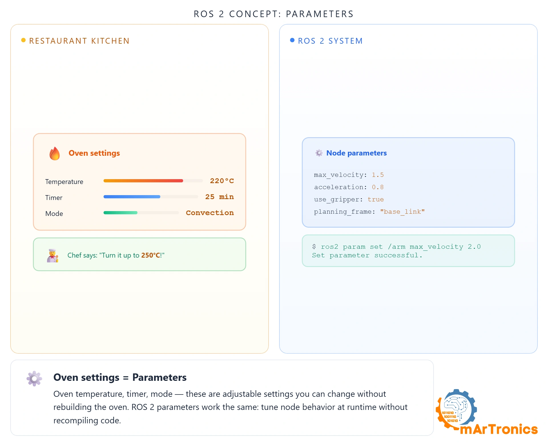
The oven temperature dial. Turn it from 180 to 220, the oven keeps running, nothing else changes. That’s a parameter: a configuration value you can tweak at runtime without restarting anything.
Each ROS 2 node owns its own parameters. No central server. Read them with ros2 param get, change with ros2 param set. Why not hardcode? Because tuning a robot means changing numbers constantly. PID gains, update rates, velocity limits. If every tweak required a recompile, I’d still be tuning the shoulder joint six months later.
OmArm Zero’s joint_trajectory_controller has PID gains per joint (Revolute 1: p=200, d=20) in gazebo_controllers.yaml. You can adjust them live while watching the arm respond in Gazebo.
Launch files: the morning opening checklist
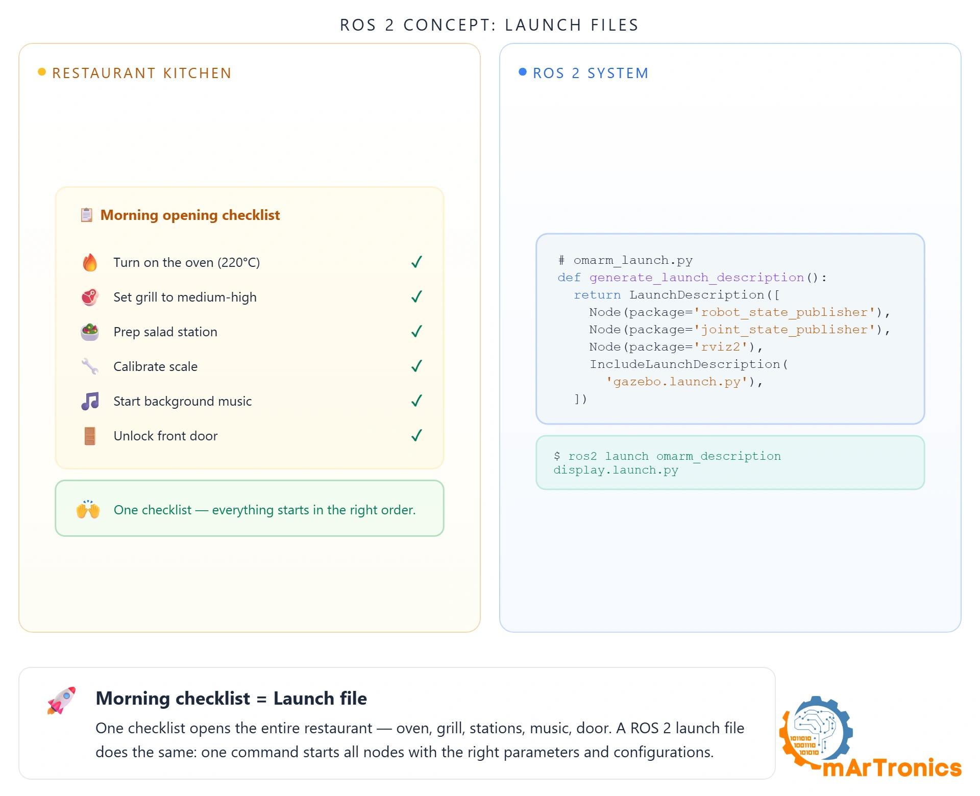
Every morning, the kitchen follows the same checklist: oven on, grill lit, stations prepped, staff assigned. Without it the manager does everything manually, in order, one at a time.
A launch file is that checklist. One Python script starts all the nodes, sets parameters, wires connections. Without it, you’d open a new terminal for every single node. With a 5-node system like OmArm Zero, that gets old fast.
Two launch files cover everything:
# RViz visualization (interactive joint sliders)
ros2 launch omarm_zero_description display.launch.py

# Full Gazebo simulation (physics, controllers, bridge)
ros2 launch omarm_zero_description gazebo.launch.py
3. Packages and workspaces: organizing the kitchen
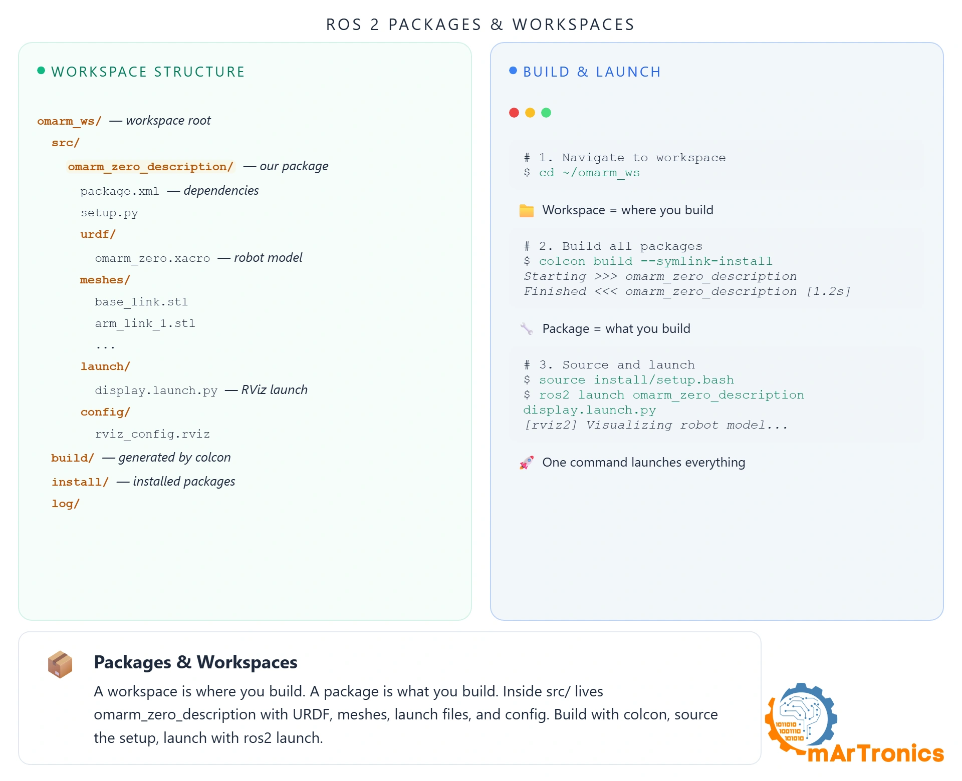
The restaurant building is the workspace. Kitchen, bar, front of house are departments (packages). They share the building but operate independently, each with their own recipes and staff.
In ROS 2: a workspace is a directory. Inside src/, each package is a self-contained module with its own code, configs, launch files, and dependencies. OmArm Zero’s workspace:
omarm_zero_ws/
+-- src/
|   +-- omarm_zero_description/      -- URDF, meshes, launch, configs
|   +-- omarm_zero_moveit_config/    -- MoveIt planning configuration
|   +-- omarm_zero_gamepad_control/  -- Gamepad teleoperation
|   +-- omarm_zero_real_control/     -- Real hardware interface
+-- build/    -- generated by colcon
+-- install/  -- generated by colcon
+-- log/
Why bother? Because packages are independent. Someone who just wants the OmArm Zero URDF clones omarm_zero_description into their workspace. They don’t need the gamepad or MoveIt packages. Each package declares dependencies in package.xmlو colcon build handles the rest.
Two commands from source to running system:
cd ~/omarm_zero_ws
colcon build
source install/setup.bash
After sourcing, all packages are on the ROS path and you can launch any node from any package.
4. TF2: coordinate transforms
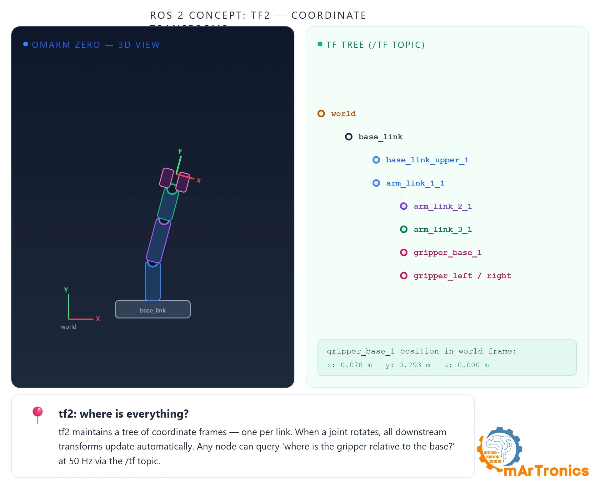

This concept trips up more beginners than anything else, but it’s also what makes everything else possible. The question TF2 answers: “Where is the gripper right now, relative to the base?”
Every joint adds a coordinate frame. Base has an origin. Shoulder rotates, new frame. Elbow rotates, another frame. All the way to the gripper. TF2 tracks all of them in real time. Think of it as GPS for the inside of your robot. Any node can ask “where is gripper_base_1 in the world frame?” and TF2 chains through every joint to give you the answer.
OmArm Zero’s transform tree:
world -> base_link -> base_link_upper_1 -> arm_link_1_1 -> arm_link_2_1 -> arm_link_3_1
    -> gripper_base_1 +-- gripper_left_1
                      +-- gripper_right_1
Each arrow is a transform published by robot_state_publisher, updated every time a joint moves. Inspect the full tree with:
ros2 run tf2_tools view_frames
This spits out a PDF showing every frame and who’s broadcasting it. First thing to reach for when something shows up in the wrong place.
In practice: when MoveIt plans a path, it asks TF2 where the gripper is now (forward kinematics) and what joint angles would put it somewhere else (inverse kinematics). If the transforms are wrong or stale, the planner plans for a robot that doesn’t match reality. I learned this the hard way when my gripper kept missing objects by 3cm.
5. Setting up the environment
You need Linux (or WSL2 on Windows) with at least 8 GB RAM. I’m running Ubuntu 22.04 with ROS 2 Jazzy and Gazebo Harmonic. Other distros work but expect more friction during setup.
Install ROS 2 Jazzy
Follow the official installation guide at docs.ros.org. The short version:
sudo apt install software-properties-common
sudo add-apt-repository universe
sudo apt update && sudo apt install curl -y
sudo curl -sSL https://raw.githubusercontent.com/ros/rosdistro/master/ros.key -o /usr/share/keyrings/ros-archive-keyring.gpg
echo "deb [arch=$(dpkg --print-architecture) signed-by=/usr/share/keyrings/ros-archive-keyring.gpg] http://packages.ros.org/ros2/ubuntu $(. /etc/os-release && echo $UBUNTU_CODENAME) main" | sudo tee /etc/apt/sources.list.d/ros2.list > /dev/null
sudo apt update && sudo apt install ros-jazzy-desktop -y
Source the setup file in every new terminal:
source /opt/ros/jazzy/setup.bash
Add it to your .bashrc so you don’t have to type it every time:
echo "source /opt/ros/jazzy/setup.bash" >> ~/.bashrc
Install Gazebo Harmonic
Gazebo handles physics, rendering, and sensors. Install it with the ROS 2 bridge packages:
sudo apt install ros-jazzy-ros-gz ros-jazzy-gz-ros2-control ros-jazzy-gz-ros2-control-demos -y
Install additional dependencies
Control packages and joint state publisher for RViz:
sudo apt install ros-jazzy-ros2-control ros-jazzy-ros2-controllers ros-jazzy-joint-state-publisher-gui ros-jazzy-xacro -y
Verify the installation
printenv ROS_DISTRO
gz sim --version
The first command should print jazzy. The second should return a Gazebo version number. If gz sim fails, you’re probably missing the gz-harmonic meta-package.
Clone the OmArm Zero workspace
mkdir -p ~/omarm_zero_ws/src
cd ~/omarm_zero_ws/src
git clone https://github.com/ODraidrya/OmArm-Zero-ROS2.git omarm_zero_description
cd ~/omarm_zero_ws
colcon build
source install/setup.bash
Everything installed. Now we teach ROS 2 what our arm actually looks like.
6. URDF and Xacro: describing your robot
At this point ROS 2 is installed but it knows nothing about our arm. How many joints? How long are the links? Where’s the gripper? What does it weigh? Without answers to these questions, RViz can’t render it, Gazebo can’t simulate it, and MoveIt can’t plan for it.
URDF (Unified Robot Description Format) is the answer. It’s an XML file that describes everything: rigid bodies, joints, rotation axes, mass properties. You write it once, and every tool reads from it. One file, one source of truth.
You can’t just import a CAD file directly. STL gives you geometry but nothing about which parts move or where the axes are. URDF adds that kinematic layer on top.
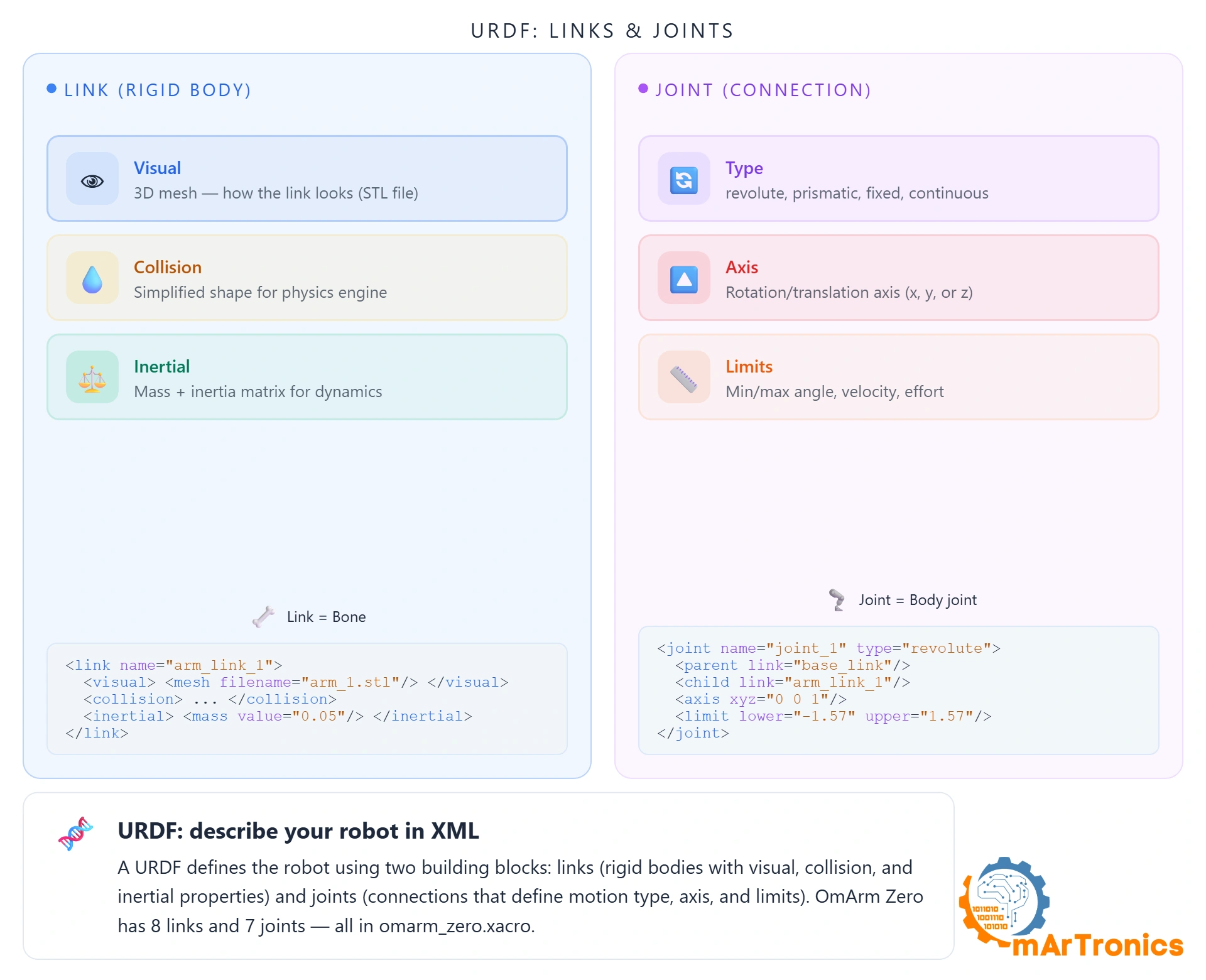
Two building blocks: links (rigid bodies) and joints (connections). Let me show you each one, then how to create the file from scratch and from CAD.
Links: the rigid bodies
A link is one physical piece. For OmArm Zero: base, two arm segments, wrist, gripper base, two fingers. Each defines three things:
Visual — the 3D shape rendered in RViz/Gazebo. STL meshes from CAD:
<link name="base_link">
  <visual>
    <geometry>
      <mesh filename="file://$(find omarm_zero_description)/meshes/base_link.stl"
            scale="0.001 0.001 0.001"/>
    </geometry>
    <material name="silver"/>
  </visual>
</link>
Collision — a simplified shape for physics. Can be the same mesh (slower, accurate) or a primitive like a cylinder (faster, approximate). OmArm Zero uses full meshes since it’s small enough that performance isn’t an issue.
Inertial — mass, center of mass, inertia tensor. Without these, Gazebo ignores gravity and collisions produce no forces. I exported them from CAD:
<inertial>
  <origin xyz="-0.000886 0.019817 0.028036" rpy="0 0 0"/>
  <mass value="0.2095"/>
  <inertia ixx="0.000388" iyy="0.000273" izz="0.000577"
           ixy="1.2e-05" iyz="-1.5e-05" ixz="2e-06"/>
</inertial>
Joints: the connections
A joint connects two links and defines how they move. OmArm Zero has 7 revolute joints (5 arm + 2 gripper). Each specifies: type (revolute/continuous/prismatic/fixed), parent and child links, rotation axis, and limits (angle range, max velocity, max torque).
The shoulder joint:
<joint name="Revolute 1" type="revolute">
  <origin xyz="0.0 0.0 0.05087" rpy="0 0 0"/>
  <parent link="base_link"/>
  <child link="base_link_upper_1"/>
  <axis xyz="0.0 0.0 1.0"/>
  <dynamics damping="2.0" friction="0.02"/>
  <limit lower="0.0" upper="3.14" effort="40.0" velocity="0.2"/>
</joint>
Revolute 1 connects base_link to base_link_upper_1, rotates around Z, moves 0-3.14 rad (0-180°), with damping to prevent oscillation in simulation.
Xacro: URDF without the copy-paste nightmare
Raw URDF gets verbose fast. OmArm Zero is over 250 lines and it’s a small arm. Xacro (XML Macros) adds variables, math, and includes. The Gazebo config lives in its own file:
<xacro:include filename="$(find omarm_zero_description)/urdf/omarm_zero.gazebo" />
At build time, xacro.process_file() expands everything into one URDF string.
The ros2_control block
At the bottom of the URDF, a <ros2_control> section tells the control framework which joints exist and what interfaces they expose:
<ros2_control name="GazeboSystem" type="system">
  <hardware>
    <plugin>gz_ros2_control/GazeboSimSystem</plugin>
  </hardware>
  <joint name="Revolute 1">
    <command_interface name="position"/>
    <state_interface name="position"/>
    <state_interface name="velocity"/>
  </joint>
  <!-- ... same for Revolute 2-7 -->
</ros2_control>
This connects URDF to the control stack: use Gazebo as hardware abstraction, expose position commands and state interfaces per joint. For real hardware, you swap the plugin. Everything else stays identical. That’s the whole trick of ros2_control.
7. Creating the URDF: manual workflow and Fusion 360 export
Two ways to create a URDF: write it by hand (good for learning, painful for anything big) or export from CAD (fast, less error-prone). I did both. CAD export for the heavy lifting, then hand-editing to fix joint limits and add controller config.
Writing by hand
Every URDF starts with a <robot> tag and a fixed “world” frame:
<?xml version="1.0" ?>
<robot name="omarm_zero" xmlns:xacro="http://www.ros.org/wiki/xacro">
  <link name="world"/>
  <joint name="world_to_base" type="fixed">
    <parent link="world"/>
    <child link="base_link"/>
  </joint>
  <!-- ... all links and joints go here ... -->
</robot>
From there, you work your way along the kinematic chain: define a link, then define the joint that connects it to the next link, then define that link, and so on. For OmArm Zero, the chain is: world → base_link → base_link_upper_1 → arm_link_1_1 → arm_link_2_1 → arm_link_3_1 → gripper_base_1 → gripper fingers.
Where do the numbers come from?
Origins and offsets: from CAD joint definitions, or measured with calipers if you don’t have CAD. Expect trial and error in RViz until things line up.
Rotation axes: look at the joint. Base rotates left-right? That’s 0 0 1 (Z). Elbow bends forward? 0 1 0 (Y). OmArm Zero has some ugly axes like 0.016327 0.999867 0.0 for Revolute 2 because nothing in the real world aligns perfectly with global axes.
Inertial properties: mass, center of mass, inertia tensor. Skip these and Gazebo loads but ignores gravity. Not optional for simulation.
Joint limits: I physically moved each joint to its mechanical stops, wrote down the angles, converted to radians. That’s it.
My advice: add one link-joint pair at a time and check in RViz after each. Trying to debug a full 8-link URDF at once is miserable. I wasted an entire afternoon on that before switching to incremental testing.
From CAD to URDF: the Fusion 360 workflow
Measuring offsets and computing inertia tensors by hand is tedious. Since I had the full model in Fusion 360, I used fusion360-urdf-ros2 by Lentin Joseph (based on work by syuntoku14 و dheena2k2). It reads your assembly and exports a complete ROS 2 package: Xacro, STL meshes, launch files. Saves hours. Doesn’t replace understanding URDF (which is why I explained it first), but eliminates measurement errors.
My workflow:
Step 1: Install the plugin
Open Fusion 360, press Shift + S, click the green plus next to “My Scripts”, point it to the cloned repo. Done. No dependencies, no virtual env.
Step 2: Prepare the CAD model
This step determines everything. Export quality depends on your Fusion 360 setup. Four rules:
Set the coordinate system using the right-hand rule. Base at the origin, Z pointing up. Fusion 360’s default (X-right, Y-forward, Z-up) already matches ROS convention. Make sure the first joint’s rotation axis aligns with Z.
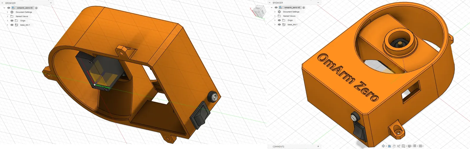
Name the root component base_link. The plugin uses component names as URDF link names. ROS 2 convention says the bottom link is base_link. I renamed mine; everything else derives from Fusion component names.
Convert all bodies to components. The plugin treats each component as a URDF link. Bodies inside a single component get merged. Right-click each body, “Create Components from Bodies”.
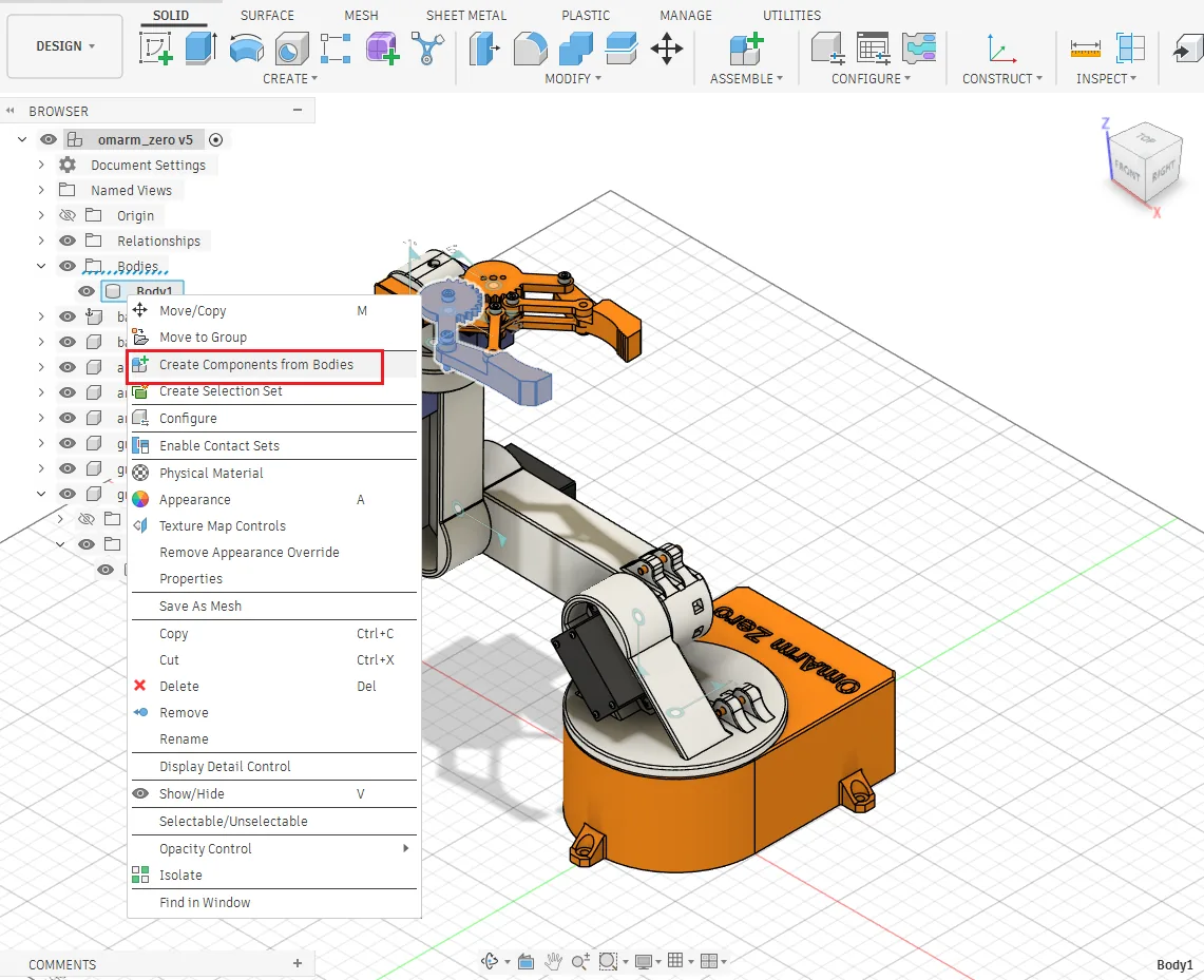
Turn off “Capture Design History” before exporting. Easy to forget, breaks everything if you don’t. Right-click top-level component → “Do not capture Design History”. Turn it back on after export.
Step 3: Define joints in Fusion 360
For every physical joint, create a matching Fusion 360 joint (Assemble → Joint). Key gotcha:
إن parent component must be Component2 (the second selection in the dialog). Counterintuitive. Getting it backwards flips your kinematic chain and you won’t understand why the arm is inside-out in RViz.
Each joint is revolute. Place the origin where the servo horn sits. Test motion in Fusion before exporting: click the joint, drag the handle, verify rotation direction. Fixing it here takes 10 seconds. Fixing it in URDF XML takes 30 minutes of guessing.
Important: the plugin does لا support nested components. Flatten all sub-assemblies so every URDF link is directly under root.
Step 4: Run the export
Shift + S → select fusion360-urdf-ros2 → Run. The dialog asks for an output folder and Gazebo version (I picked “Gazebo” for Harmonic). It reads components, joints, materials, exports STL meshes, computes inertia, and generates the full package.
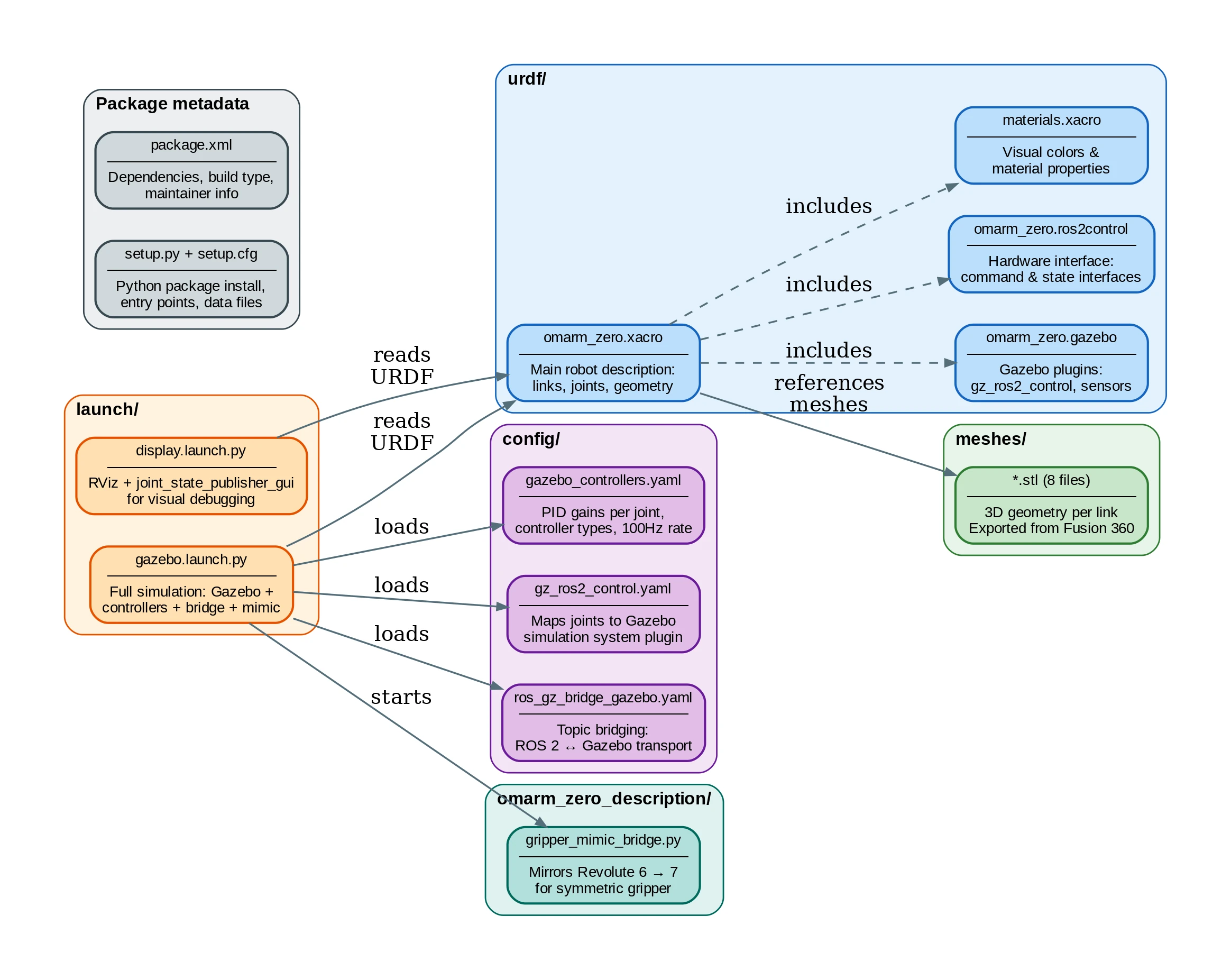
Generated package:
omarm_zero_description/
+-- urdf/          (omarm_zero.xacro, .gazebo, .ros2control, materials.xacro)
+-- meshes/        (base_link.stl, base_link_upper_1.stl, arm_link_{1,2,3}_1.stl,
|                   gripper_base_1.stl, gripper_{left,right}_1.stl)
+-- launch/        (display.launch.py, gazebo.launch.py)
+-- config/        (gazebo_controllers.yaml, gz_ros2_control.yaml, ros_gz_bridge_gazebo.yaml)
+-- bin/           (mock_gazebo_sim)
+-- omarm_zero_description/  (gripper_mimic_bridge.py)
+-- package.xml
+-- setup.py
+-- setup.cfg
Copy it into your workspace and build:
# Create the workspace if you haven't already
mkdir -p ~/omarm_zero_ws/src

# Copy the exported package into the workspace
cp -r omarm_zero_description ~/omarm_zero_ws/src/

# Build
cd ~/omarm_zero_ws
colcon build
source install/setup.bash
Test immediately:
ros2 launch omarm_zero_description display.launch.py
ros2 launch omarm_zero_description gazebo.launch.py
Out of the box you get: valid Xacro, meshes, inertia, launch files. What’s missing: Gazebo plugins (gz_ros2_control), controller configs, correct joint limits. Those I added by hand.
Step 5: Post-export fixes
The export is a starting point, not a finished product. Things I had to fix:
Joint directions. “Positive rotation” in Fusion doesn’t always match servo positive. I launched RViz, moved each slider, compared with the physical arm. Wrong direction? Flip the axis (0 0 1 → 0 0 -1).
Joint limits. Export often has no <limit> tags or wrong defaults. I moved each real joint to its stops, noted the angles, converted to radians:
<limit lower="0" upper="3.14159" velocity="1.0" effort="1.0"/>
Base (Revolute 1) goes 0-180° (0 to Ï rad). Elbows go -180° to 0°. Get these wrong and the sim arm reaches impossible positions, making all your PID tuning worthless.
Inertial properties. Plugin computes from Fusion materials. If you left “Steel” but your arm is PLA, values are wildly off. I weighed the real arm (~500g), compared with the URDF total, adjusted materials, re-exported. If the sim arm is 10x heavier than reality, PID gains won’t transfer.
Mesh scale. Fusion exports in mm, ROS expects meters. The plugin adds scale="0.001 0.001 0.001". Check it’s there. Missing it makes your robot 1000x too large in RViz, which is entertaining exactly once.
Controller configuration. The export includes no controllers. I added gazebo_controllers.yaml with PID gains, configured joint_trajectory_controller و joint_state_broadcaster, and added the gz_ros2_control plugin to the Xacro. PID tuning took many iterations. Arm oscillates? P too high. Collapses under gravity? Controllers didn’t load. I started conservative (low P, no I, moderate D) and worked up. Details in Section 10.
After these fixes: simulation-ready URDF, proper limits, correct inertia, working controllers. Time to see it move.
8. Visualizing in RViz
RViz reads the URDF, subscribes to /tf, and renders the 3D model. No physics, no gravity. It just shows what the robot looks like at the current joint angles. A mirror for your URDF. If the description is wrong, you see it instantly.
Launch with interactive sliders:
ros2 launch omarm_zero_description display.launch.py
Three nodes start: robot_state_publisher, joint_state_publisher_gui (sliders), and rviz2. Drag a slider, the joint rotates in 3D.
The slider GUI is your debugging lifeline. Move “Revolute 1” and the base should rotate. If instead some link flies into space, your origin or axis is wrong.
Correct: links form a chain base-to-gripper, each joint only moves downstream parts, nothing intersects.
Wrong: link at world origin (bad <origin>), sideways bend when it should go forward (wrong axis), gripper 1000x too large (missing scale="0.001").
I spent about an hour going back and forth. Change one number, save, kill launch, re-launch, check. Tedious. But if it looks right in RViz, the URDF is right. If it doesn’t, don’t touch Gazebo yet.
9. Simulating in Gazebo
Gazebo adds physics. Gravity, friction, collisions, contact forces. The arm falls if it has no controller. Objects collide realistically. Under the hood, a control stack (Section 10) manages communication between your commands and the simulated joints.
Full simulation:
ros2 launch omarm_zero_description gazebo.launch.py
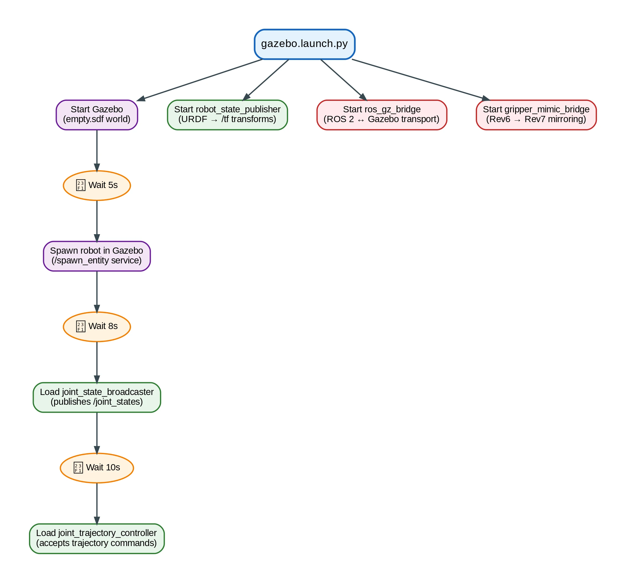
The launch sequence:
- Start Gazebo with empty world
- Start
robot_state_publisherwith processed URDF - Spawn robot (5s delay for Gazebo to initialize)
- Load controllers:
joint_state_broadcasterثمjoint_trajectory_controller - Start ROS-Gazebo bridge (clock, states, commands)
- Start gripper mimic bridge (Revolute 6 → Revolute 7)
The delays matter. Gazebo takes seconds to fully start. Spawn before it’s ready and the service doesn’t exist yet. Fails silently. TimerAction(period=5.0) handles it.
Send the arm somewhere:
ros2 topic pub --once /joint_trajectory_controller/joint_trajectory \
  trajectory_msgs/msg/JointTrajectory \
  "{joint_names: ['Revolute 1', 'Revolute 2', 'Revolute 3', 'Revolute 4', 'Revolute 5', 'Revolute 6'],
    points: [{positions: [1.57, -1.57, -1.57, -1.57, -1.57, 0.0],
              time_from_start: {sec: 3, nanosec: 0}}]}"
The arm moves smoothly to target over 3 seconds. The trajectory controller interpolates between current and target angles, respecting velocity limits. First time I saw this work, after hours of debugging, I actually fist-pumped at my desk.
10. ros2_control: the control architecture
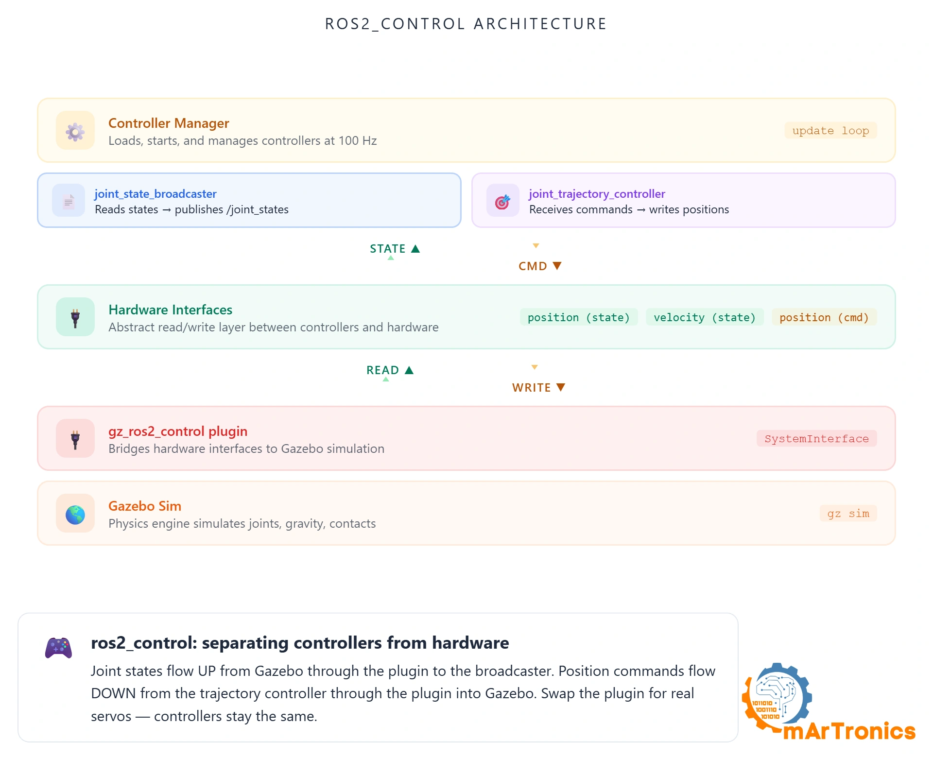
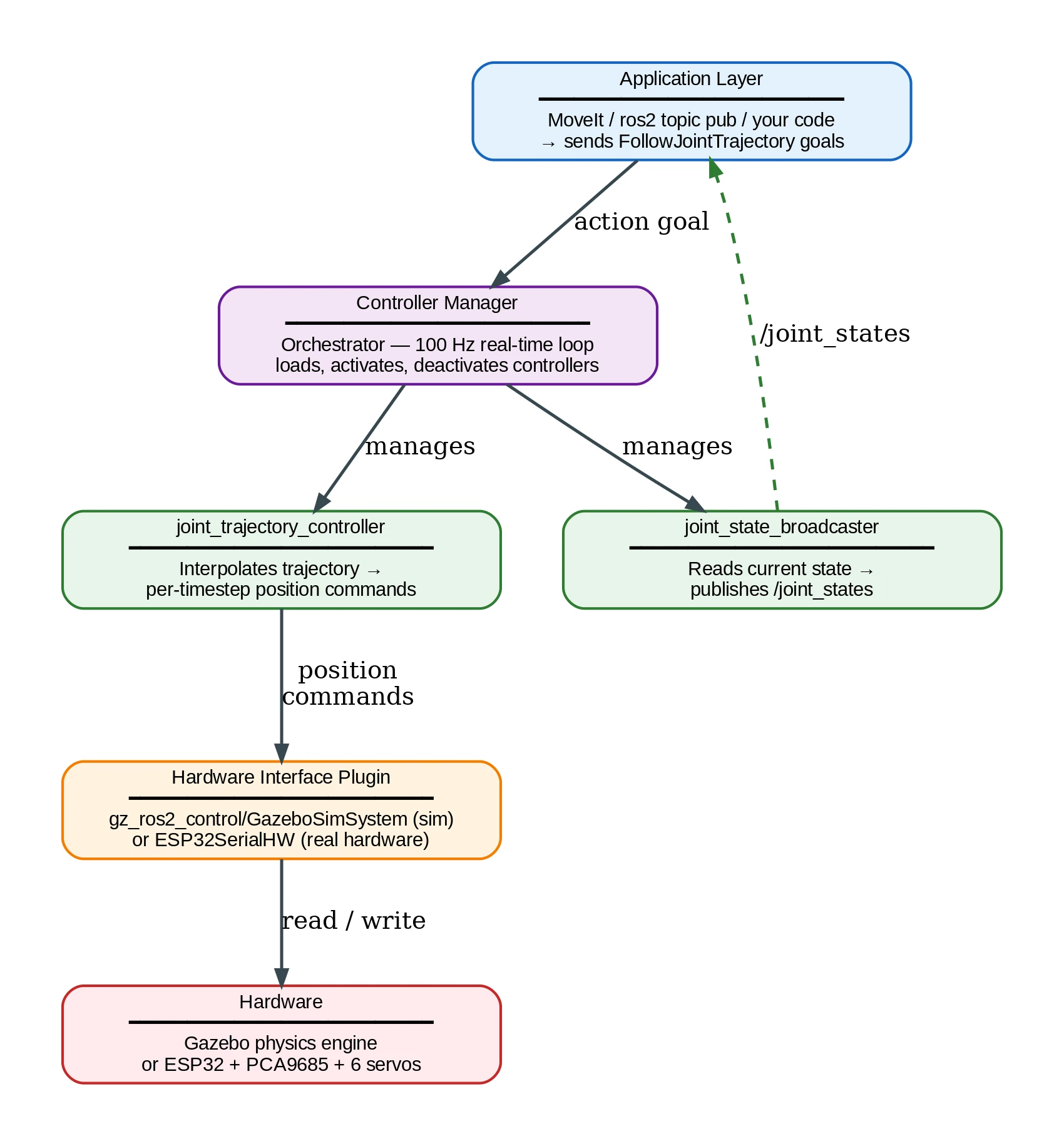
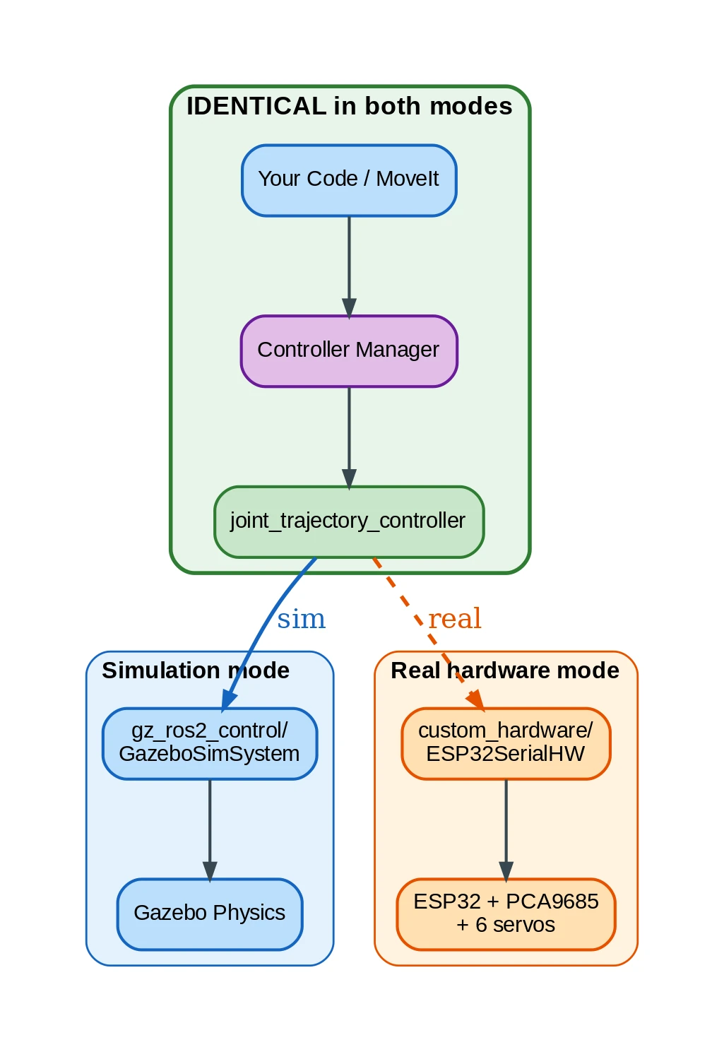
This is what makes “develop in sim, deploy to real hardware” actually work. ros2_control is a layered stack. Application sends goals at the top. Hardware moves at the bottom. Everything in between can be swapped independently. The trick: everything above the hardware plugin stays identical whether you’re in Gazebo or on the real ESP32.
The stack:
Application layer: MoveIt, your code, or ros2 topic pub. Sends trajectory goals.
Controller Manager: loads controllers, manages lifecycle, runs the control loop at 100 Hz.
Controllers: joint_trajectory_controller interpolates trajectories into per-timestep commands. joint_state_broadcaster publishes current state. Both are plugins from ros2_controllers.
Hardware Interface: plugin that speaks hardware. Sim: gz_ros2_control/GazeboSimSystem. Real: custom plugin talking to ESP32 over Wi-Fi.
Hardware: Gazebo physics engine, or real ESP32 + PCA9685 + servos.
Configuration in gazebo_controllers.yaml:
controller_manager:
  ros__parameters:
    update_rate: 100
    joint_state_broadcaster:
      type: joint_state_broadcaster/JointStateBroadcaster
    joint_trajectory_controller:
      type: joint_trajectory_controller/JointTrajectoryController

joint_trajectory_controller:
  ros__parameters:
    joints:
      - Revolute 1
      - Revolute 2
      - Revolute 3
      - Revolute 4
      - Revolute 5
      - Revolute 6
      - Revolute 7
    command_interfaces:
      - position
    state_interfaces:
      - position
      - velocity
    gains:
      "Revolute 1": {p: 200.0, i: 1.0, d: 20.0, i_clamp: 10.0}
      "Revolute 2": {p: 300.0, i: 1.0, d: 30.0, i_clamp: 10.0}
      "Revolute 3": {p: 200.0, i: 1.0, d: 20.0, i_clamp: 10.0}
      "Revolute 4": {p: 150.0, i: 0.5, d: 15.0, i_clamp: 10.0}
      "Revolute 5": {p: 100.0, i: 0.5, d: 10.0, i_clamp: 10.0}
      "Revolute 6": {p: 10.0, i: 0.05, d: 1.0, i_clamp: 1.0}
      "Revolute 7": {p: 10.0, i: 0.05, d: 1.0, i_clamp: 1.0}
Gains decrease base-to-tip. Shoulder (Revolute 1-2) carries the full arm weight: needs p=200-300. Gripper fingers (Revolute 6-7) are tiny: p=10 is enough. Get these wrong and you’ll either oscillate violently or sag under gravity. I spent a full evening tuning these. Not glamorous work, but the arm moves right or it doesn’t.
11. The gripper mimic bridge
The gripper has two fingers that should mirror each other. Left closes, right closes the same amount in the opposite direction. Mechanically this would be a gear linkage. In simulation, software.
إن gripper_mimic_bridge node reads Revolute 6 position from /joint_states, negates it, publishes a trajectory for Revolute 7. 40 lines of Python.
URDF has a <mimic> tag for exactly this, but Gazebo Harmonic doesn’t support it through ros2_control. The bridge is the workaround. Simple, works, avoids hacking the controller config.
12. Launch files that tie it all together
Here’s how the startup sequence from Section 9 translates to Python. Structure only (full file in the repo):
def generate_launch_description():
    # Process URDF from Xacro into a string
    robot_description_config = xacro.process_file(robot_description_file)
    robot_description_xml = robot_description_config.toxml()

    # robot_state_publisher needs the URDF string as a parameter
    robot_state_publisher = Node(
        package='robot_state_publisher',
        executable='robot_state_publisher',
        parameters=[{'robot_description': robot_description_xml,
                     'use_sim_time': True}],
    )

    # Gazebo launch: an empty world
    gazebo = IncludeLaunchDescription(...)

    # Spawn AFTER Gazebo is ready (5s delay)
    spawn_robot = TimerAction(period=5.0, actions=[...])

    # Controllers AFTER the robot exists (8s, 10s delays)
    ensure_joint_state_broadcaster = TimerAction(period=8.0, ...)
    ensure_joint_trajectory_controller = TimerAction(period=10.0, ...)

    # Bridge and gripper mimic run alongside everything
    ros_gz_bridge = Node(package='ros_gz_bridge', ...)
    gripper_mimic_bridge = Node(package='omarm_zero_description', ...)
The key detail: TimerAction. Gazebo takes ~4 seconds to start on my machine. Spawn before that? Silent failure. Controllers need the robot to exist first. Trajectory controller needs state broadcaster active. The 5→8→10 second cascade gives each layer time. On slower machines, bump these up. If “nothing happens” after launch, this is the first suspect.
13. Testing and validation
Simulation running? Go through these checks:
Nodes: ros2 node list should show /robot_state_publisher, /controller_manager, /gripper_mimic_bridge, and Gazebo nodes. Missing? Check terminal errors.
Joint states:
ros2 topic hz /joint_states
Should be ~50 Hz. Nothing? joint_state_broadcaster didn’t load.
TF tree:
ros2 run tf2_tools view_frames
PDF with every frame from world to gripper fingers. Missing frames = broken joint chain in URDF.
Controllers:
ros2 control list_controllers
Want both [active]. If trajectory controller is inactive: ros2 control load_controller --set-state active joint_trajectory_controller.
Move it:
ros2 topic pub --once /joint_trajectory_controller/joint_trajectory \
  trajectory_msgs/msg/JointTrajectory \
  "{joint_names: ['Revolute 1', 'Revolute 2', 'Revolute 3', 'Revolute 4', 'Revolute 5', 'Revolute 6'],
    points: [{positions: [1.57, -1.0, -2.0, -1.57, -1.57, -0.3],
              time_from_start: {sec: 4, nanosec: 0}}]}"
Smooth motion = gains are right. Oscillation = reduce p. Too slow = increase p or reduce d.
Common problems
Every one of these cost me at least an hour. Hopefully you get to skip that:
Robot doesn’t appear in Gazebo. Spawn ran before Gazebo finished. Increase TimerAction delay to 8+ seconds. Terminal shows [spawn_entity]: Waiting for service /world/empty/create if this is happening.
Arm collapses under gravity. Controllers didn’t load. ros2 control list_controllers shows nothing. Cause: typo in the gz_ros2_control plugin YAML path, or spawn delay too short.
Joint oscillates endlessly. P gain too high. Cut it in half. Still oscillating? Increase D. Tip joints (gripper) need much lower gains than base joints.
Arm vibrates/jitters in place. Integral gain accumulating error. Lower i_clamp or set i to zero. For hobby servos, integral rarely helps.
Links in wrong position (RViz). مشترك <origin> xyz is relative to parent frame, not world. Common trap: forgetting mm→m conversion in origins while meshes have correct scale.
“Package not found” after successful build. Forgot source install/setup.bash. Needs to happen in every new terminal. Put it in .bashrc.
14. What comes next
The digital twin works. You can crash it, test trajectories, tune controllers, and nothing real breaks. In Part 3 we add MoveIt 2: drag a marker in RViz and the arm plans a collision-free path. We also bridge to real hardware through a custom ros2_control plugin that talks to the ESP32 over Wi-Fi. Same code, real servos.
Full source code: OmArm-Zero-ROS2 on GitHub
الأسئلة المتداولة
What is URDF in ROS 2?
URDF (Unified Robot Description Format) is an XML file that describes a robot’s physical structure: links (rigid bodies), joints (connections), meshes (3D shapes), and inertial properties. Every ROS 2 visualization and simulation tool reads from it. You write it once, and RViz, Gazebo, MoveIt, and TF2 all use the same file.
How do I visualize a robot arm in RViz?
Create a URDF describing your arm, then run ros2 launch مع robot_state_publisher و joint_state_publisher_gui. RViz subscribes to the /tf topic and renders the 3D model. You get interactive sliders to move each joint in real time.
Can I simulate a robot in Gazebo without ROS 2?
Yes, but you lose the integration. Without ROS 2, Gazebo can simulate physics but you can’t use ros2_control, MoveIt, or any ROS 2 controller. The ros2_control bridge is what lets you swap between simulation and real hardware with zero code changes.
How do I export a URDF from Fusion 360?
استخدم fusion360-urdf-ros2 plugin. Prepare your model (Z-up, components named, joints defined), turn off design history, run the script. It exports meshes, inertia, and a full ROS 2 package. You’ll still need to hand-edit joint limits and add controller config.
Why does my robot collapse in Gazebo?
The controllers didn’t load. Run ros2 control list_controllers to check. Common causes: the spawn delay is too short (increase TimerAction to 8+ seconds), there’s a typo in the YAML path for gz_ros2_control, or the ros2_control block in your URDF doesn’t match the controller config.
What’s the difference between RViz and Gazebo?
RViz is a viewer. It shows what your robot looks like at given joint angles but doesn’t simulate physics. Gazebo is a simulator. It computes gravity, friction, collisions, and contact forces. Use RViz to verify your URDF is correct, then Gazebo to test that your controllers work under realistic conditions.