
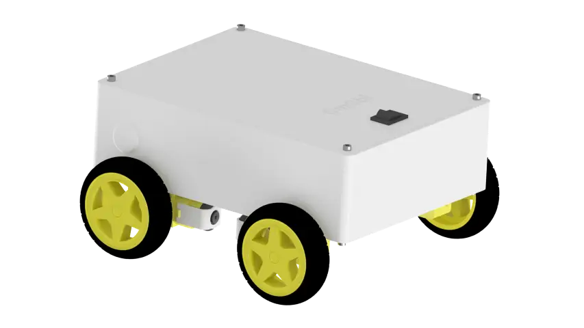
Have you ever wanted to build a robot car you can drive from your phone? In this step-by-step OmObi robot car tutorial, you will build a fully functional Bluetooth controlled robot car using an Arduino Uno, an HC-05 Bluetooth module, and the Adafruit Motor Shield V1.2. This is one of the most rewarding DIY Bluetooth controlled car Arduino projects for beginners and hobbyists alike.
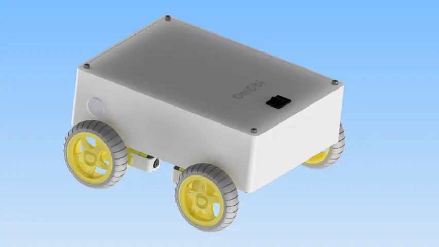
This complete guide walks you through every stage of the build: assembling the four-wheel-drive chassis, wiring the motors and Bluetooth module, uploading the Arduino code, and creating a custom Android control app with MIT App Inventor. By the end, you will have a wireless robot car that responds to forward, backward, left, right, and stop commands from your smartphone.
If you are new to Bluetooth communication with Arduino, consider reading our شرح كامل لتقنية بلوتوث أردوينو HC-05/HC-06 first. For a general introduction to Arduino programming, see our دليل أساسيات برمجة أردوينو.
ما ستتعلمه
By following this OmObi robot car tutorial from start to finish, you will learn how to:
- Build the OmObi four-wheel-drive robot car chassis using a 3D-printed frame and motor mounts
- افهم كيف تتحكم لوحة Adafruit Motor Shield في أربعة محركات تيار مستمر في وقت واحد
- قم بتوصيل وحدة بلوتوث HC-05 بلوحة أردوينو للاتصال التسلسلي اللاسلكي
- اكتب كود أردوينو الذي يفسر أوامر البلوتوث المكونة من حرف واحد ويشغل المحركات وفقًا لذلك.
- قم بإنشاء تطبيق تحكم بسيط لنظام Android باستخدام MIT App Inventor مع أزرار اتجاهية
- اختبر، واضبط، واستكشف أعطال سيارة الروبوت التي يتم التحكم فيها عبر البلوتوث بعد الانتهاء من تصنيعها.
How the OmObi Robot Car Works
قبل البدء بالبناء، من المفيد فهم كيفية عمل جميع الأجزاء معًا في مشروع سيارة الروبوت هذا باستخدام لوحة Adafruit Motor Shield. يتكون النظام من أربعة مكونات رئيسية: هاتف يعمل بنظام Android، ووحدة بلوتوث HC-05، ولوحة Arduino Uno، ولوحة Adafruit Motor Shield المزودة بأربعة محركات تيار مستمر.
ال هاتف أندرويد يقوم بتشغيل تطبيق مخصص تم إنشاؤه باستخدام MIT App Inventor. عند الضغط على زر اتجاهي (للأمام، للخلف، لليسار، أو لليمين)، يرسل التطبيق أمرًا مكونًا من حرف واحد (F، B، L، R، أو S للتوقف) عبر البلوتوث.
ال وحدة بلوتوث HC-05 يستقبل الجهاز هذا الأمر لاسلكيًا وينقله إلى أردوينو عبر منفذ التسلسل على المنفذين 0 (RX) و1 (TX). يعمل جهاز HC-05 كجسر تسلسلي لاسلكي بين الهاتف وأردوينو. لمعرفة المزيد حول كيفية عمل وحدتي HC-05 وHC-06، راجع دليلنا. شرح كامل لتقنية بلوتوث أردوينو HC-05/HC-06.
ال أردوينو أونو يقرأ الحرف الوارد من المخزن المؤقت التسلسلي. وبناءً على الأمر المستلم، يستدعي وظيفة الحركة المناسبة (للأمام، للخلف، الانعطاف لليسار، الانعطاف لليمين، أو التوقف).
ال لوحة محرك Adafruit الإصدار 1.2 sits on top of the Arduino and drives four DC motors through its M1, M2, M3, and M4 output terminals. The shield uses the AFMotor library to control motor direction (FORWARD, BACKWARD, RELEASE) and speed (0 to 255). In this project, the left-side motors connect to M1 and M2, and the right-side motors connect to M3 and M4. For turning, one side runs forward while the other runs backward, creating a tank-style turn.
For a deeper look at motor driver principles, see our شرح استخدام محرك L298N مع أردوينو.
Complete Bill of Materials for the OmObi Robot Car
فيما يلي قائمة كاملة بالمواد اللازمة لمشروع سيارة أردوينو يتم التحكم بها عبر البلوتوث، والذي يمكنك تنفيذه بنفسك. معظم المكونات متوفرة على نطاق واسع عبر الإنترنت أو في مجموعات أدوات الإلكترونيات للمبتدئين.
| عنصر | الكمية | مطلوب؟ | غاية | ملحوظات |
|---|---|---|---|---|
| أردوينو أونو | 1 | مطلوب | وحدة التحكم الدقيقة الرئيسية | أي لوحة متوافقة مع Uno تعمل |
| لوحة محرك Adafruit الإصدار 1.2 | 1 | مطلوب | يقوم بتشغيل أربعة محركات تيار مستمر | يتم وضعها مباشرة فوق الأردوينو |
| وحدة بلوتوث HC-05 | 1 | مطلوب | الاتصال التسلسلي اللاسلكي مع الهاتف | يعمل HC-06 أيضًا (كجهاز تابع فقط) |
| محركات التيار المستمر المزودة بعلب تروس | 4 | مطلوب | قيادة السيارات ذات الأربع عجلات | Typically 3-6 V geared motors |
| عجلات | 4 | مطلوب | قم بتثبيته على أعمدة المحرك | قم بمطابقة حجم عمود علبة التروس الخاصة بك |
| 3D-Printed Chassis | 1 | مطلوب | Robot car base frame | Plexiglas or acrylic sheet also works |
| حوامل محركات مطبوعة بتقنية الطباعة ثلاثية الأبعاد | 4 | خياري | قم بتثبيت المحركات على الهيكل | يمكن استبدالها بأقواس معدنية على شكل حرف L |
| حامل أردوينو مطبوع بتقنية الطباعة ثلاثية الأبعاد | 1 | خياري | قم بتثبيت أردوينو على الهيكل | يمكن استخدام الشريط اللاصق ذي الوجهين أو الفواصل أيضًا |
| Battery Pack (4xAA or similar) | 1 | مطلوب | يُشغّل المحركات ولوحة أردوينو | يوصى باستخدام عبوة 6 فولت؛ استخدم بطاريات جديدة |
| أسلاك توصيل | عديد | مطلوب | قم بتوصيل HC-05 بـ Arduino | محول ذكر إلى أنثى لدبابيس رأس HC-05 |
| البراغي، والصواميل، والمسامير الفاصلة | تشكيلة متنوعة | مطلوب | التجميع الميكانيكي | مقاس M3 شائع |
| هاتف ذكي يعمل بنظام أندرويد | 1 | مطلوب | يقوم بتشغيل تطبيق التحكم الخاص بـ MIT App Inventor | يجب أن يدعم تقنية بلوتوث الكلاسيكية |
Step 1: Mounting the Motors and Wheels
The first step in building the OmObi robot car is mounting the DC motors and wheels to the chassis.
قم بتوصيل المحركات
Use screws and nuts to secure the four DC motors to the 3D-printed motor mounts. Make sure the motor shafts point outward and that all four motors are oriented the same way so the wheels spin in the expected direction. If you do not have 3D-printed mounts, you can use metal L-brackets or hot glue as a temporary solution.
تركيب العجلات
Press the wheels onto the motor shafts. Ensure they are firmly attached and spin freely without rubbing on the chassis or each other.
Step 2: Mounting the Arduino and Motor Shield
الآن قم بتثبيت لوحة أردوينو أونو ودرع محرك أدا فروت على الهيكل.
قم بتأمين حامل أردوينو
Attach the 3D-printed Arduino holder to the center or rear of the chassis. Leave enough room at the front or sides for the battery pack. Alternatively, use standoffs with M3 screws through the Arduino mounting holes, or simply attach the board with double-sided foam tape.
ضع الأردوينو والدرع
ضع لوحة أردوينو أونو في الحامل وثبّتها بالبراغي. ثم ضع لوحة Adafruit Motor Shield فوق لوحة أردوينو، واضغط عليها برفق للتأكد من محاذاة جميع دبابيس التوصيل بشكل صحيح وتركيبها بالكامل. يجب أن تكون اللوحة مستوية تمامًا دون أي انحراف في الدبابيس.
Step 3: Wiring the Components
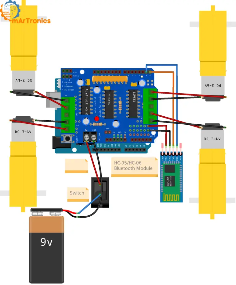
Wiring the components correctly is one of the most critical steps in building your Bluetooth controlled robot car. This section covers the motor connections, HC-05 Bluetooth wiring, and power connections. Use the wiring diagram below as a reference.
توصيلات المحرك
| محرك | محطة الدرع | موقع السيارة |
|---|---|---|
| المحرك 1 | M1 | الجانب الأيسر (الأمامي أو الخلفي) |
| المحرك 2 | M2 | الجانب الأيسر (الأمامي أو الخلفي) |
| المحرك 3 | M3 | الجانب الأيمن (الأمامي أو الخلفي) |
| المحرك 4 | M4 | الجانب الأيمن (الأمامي أو الخلفي) |
قم بتوصيل المحركين الموجودين على الجانب الأيسر بالطرفين M1 و M2، والمحركين الموجودين على الجانب الأيمن بالطرفين M3 و M4. يحتوي كل محرك على سلكين؛ أدخلهما في أطراف التوصيل اللولبية الموجودة على الغطاء وقم بربطهما بإحكام.
توصيلات وحدة بلوتوث HC-05
| دبوس HC-05 | دبوس أردوينو | ملحوظات |
|---|---|---|
| VCC | 5 فولت | يقوم بتشغيل وحدة HC-05 |
| أرضي | أرضي | أرضية مشتركة |
| TXD | RX (الطرف 0) | يقوم جهاز HC-05 بنقل البيانات إلى أردوينو |
| RXD | TX (الطرف 1) | يقوم أردوينو بإرسال البيانات إلى HC-05 |
هام: تعارضات في منفذ التسلسل (الدبابيس 0/1) والتحميل
تحذير: In this project, the HC-05 is connected to Arduino pins 0 (RX) and 1 (TX). These are the same pins used by the USB serial connection for uploading sketches and Serial Monitor communication. This means you must disconnect the HC-05 module (at least the RX/TX wires) every time you upload new code to the Arduino. If the HC-05 stays connected during upload, the upload will fail because the Bluetooth module interferes with the USB serial data. After uploading, reconnect the HC-05 and reset the Arduino.
Also, you will not be able to use Serial Monitor for debugging while the HC-05 is connected to pins 0/1. If you need simultaneous Bluetooth and Serial Monitor, use the SoftwareSerial library on different pins (for example, pins 2 and 3). For more details on wiring and using the HC-05 module, refer to our شرح استخدام تقنية البلوتوث مع أردوينو HC-05/HC-06.
توصيلات الطاقة
قم بتوصيل طرفي البطارية الموجب والسالب بمنافذ إدخال الطاقة في لوحة Adafruit Motor Shield. تُزوّد هذه اللوحة المحركات بالطاقة، كما يمكنها تزويد Arduino بالطاقة عبر منظم الجهد المدمج فيها. تأكد من أن توصيلات التأريض بين البطارية واللوحة وArduino مشتركة. استخدم بطاريات جديدة (يُفضّل 6 فولت) لضمان أداء موثوق للمحركات.
Step 4: Powering the Bluetooth-Controlled Car
For this OmObi robot car project, a 4xAA battery pack (6V total) is a practical and affordable power source. Connect the battery pack to the external power terminals on the Adafruit Motor Shield. The shield distributes power to the motors and can supply the Arduino through its power jumper.
Make sure the power switch (if using one) is accessible so you can turn the car on and off easily. Avoid using 9V block batteries because they do not provide enough current for four DC motors under load. If you want longer run time or higher torque, consider a rechargeable Li-ion pack with a voltage regulator.
Step 5: Programming the Arduino for Bluetooth Control
The Arduino sketch below receives single-character commands from the HC-05 Bluetooth module over the hardware serial connection and drives the four DC motors accordingly. This code forms the brain of your Bluetooth controlled robot car.
For a broader introduction to controlling DC motors with Arduino, see our tutorial on التحكم في محرك التيار المستمر باستخدام مشغل L298N ودرع محرك أردوينو.
مهم: افصل وحدة HC-05 عن المنفذين 0 و1 قبل تحميل هذا البرنامج. أعد توصيلها بعد اكتمال التحميل، ثم أعد تشغيل أردوينو.
مستودع GitHub: التطبيق والبرنامج
/**
 * Author: Omar Draidrya
 * Date: 2024/07/03
 * Bluetooth-controlled 4WD robot car (OmObi) using Adafruit Motor Shield V1.2 and HC-05.
 * Receives single-character commands (F/B/L/R/S) via serial from the HC-05
 * Bluetooth module and drives four DC motors on terminals M1-M4 accordingly.
 */
#include <AFMotor.h>
AF_DCMotor motor1(1);  // Create motor #1 using M1 connector
AF_DCMotor motor2(2);  // Create motor #2 using M2 connector
AF_DCMotor motor3(3);  // Create motor #3 using M3 connector
AF_DCMotor motor4(4);  // Create motor #4 using M4 connector

char command;

void setup() {
  Serial.begin(9600);     // Start serial communication at 9600 baud rate
  motor1.setSpeed(255);   // Set initial motor speeds
  motor2.setSpeed(255);
  motor3.setSpeed(255);
  motor4.setSpeed(255);
}

void loop() {
  if (Serial.available() > 0) {
    command = Serial.read();  // Read the incoming command
    if (command == 'F') { forward(); }
    else if (command == 'B') { backward(); }
    else if (command == 'L') { turnLeft(); }
    else if (command == 'R') { turnRight(); }
    else if (command == 'S') { stop(); }
  }
}

void forward() {
  motor1.run(FORWARD);
  motor2.run(FORWARD);
  motor3.run(FORWARD);
  motor4.run(FORWARD);
}

void backward() {
  motor1.run(BACKWARD);
  motor2.run(BACKWARD);
  motor3.run(BACKWARD);
  motor4.run(BACKWARD);
}

void turnLeft() {
  motor1.run(BACKWARD);
  motor2.run(BACKWARD);
  motor3.run(FORWARD);
  motor4.run(FORWARD);
}

void turnRight() {
  motor1.run(FORWARD);
  motor2.run(FORWARD);
  motor3.run(BACKWARD);
  motor4.run(BACKWARD);
}

void stop() {
  motor1.run(RELEASE);
  motor2.run(RELEASE);
  motor3.run(RELEASE);
  motor4.run(RELEASE);
}
شرح الكود: مكتبة AFMotor وإعداد المحرك
The code includes the AFMotor.h library, which is the Adafruit Motor Shield library. This library provides a simple interface to control DC motors connected to the shield. Four motor objects are created: motor1(1) through motor4(4), corresponding to the M1 to M4 terminals on the shield. In setup(), the serial communication is initialized at 9600 baud (matching the HC-05 default baud rate), and all four motors are set to full speed (255 out of 255).
شرح الكود: تخطيط المحرك (من M1 إلى M4)
المحركان 1 و2 (M1، M2) هما محركا الجانب الأيسر، والمحركان 3 و4 (M3، M4) هما محركا الجانب الأيمن. هذا التوزيع مهم لأن منطق الانعطاف يعتمد على تشغيل الجانبين الأيمن والأيسر بشكل مستقل. إذا انعطفت سيارتك في الاتجاه الخاطئ أو سارت للخلف بدلًا من الأمام، يمكنك تبديل توصيلات المحركات عند أطراف اللوحة أو تبديل قيمتي FORWARD/BACKWARD في الكود.
شرح الكود: بروتوكول أوامر البلوتوث
The command protocol is straightforward: the app sends a single ASCII character, and the Arduino reads it from the serial buffer in loop(). The five commands are F (forward), B (backward), L (turn left), R (turn right), and S (stop). This simple single-character protocol is fast and reliable for real-time control.
شرح الكود: دوال الحركة
forward() runs all four motors in the FORWARD direction, so the car drives straight ahead. backward() runs all four motors in BACKWARD. turnLeft() runs the left motors (M1, M2) backward and the right motors (M3, M4) forward, creating a tank-style left turn. turnRight() does the opposite: left motors forward, right motors backward. stop() calls RELEASE on all motors, which cuts power and lets the car coast to a halt.
كيفية تغيير السرعة
The motor speed is set in setup() using motor1.setSpeed(255). The value ranges from 0 (stopped) to 255 (full speed). To slow the car down, reduce this value. For example, 150 gives roughly 60 percent speed. You can also set different speeds for turning versus straight driving by calling setSpeed() inside the movement functions.
كيفية اختبار الكود بأمان
For your first test, prop the car up so the wheels do not touch the ground (use a box or a stack of books). This way you can verify each direction without the car driving off the table. Connect via Bluetooth, send each command from the app, and confirm all four wheels spin in the expected direction. Once verified, set the car on the floor and test at low speed by reducing setSpeed() to around 120.
Step 6: Developing the Android App for Bluetooth Control
We will use MIT App Inventor to create a simple Android app that connects to the HC-05 module over Bluetooth and sends directional commands to the Arduino. MIT App Inventor is a free, browser-based visual programming tool, ideal for beginners who want to build an HC-05 robot car app without writing Java or Kotlin code.
To understand the basics of Arduino programming that the app communicates with, refer to our دليل أساسيات برمجة أردوينو.
Register and Create a Project
Go to مخترع تطبيقات معهد ماساتشوستس للتكنولوجيا and log in with your Google account. Click “Start New Project” and name it “RobotCarControl”.
Design the User Interface
In the Designer view, add the following components to your app screen:
- منتقي القوائم – Set its text to “Select Bluetooth Device”. This lets the user choose which paired Bluetooth device to connect to.
- Label (Label1) – Add a Label component to display the connection status. The blocks will set this label to “Connected” or “Not Connected” depending on the Bluetooth connection result. This label is referenced as Label1 in the block code below, so make sure you add it to your interface.
- عميل بلوتوث – Drag this from the Connectivity palette. It is a non-visible component that handles Bluetooth communication.
- Four Buttons – Add buttons named ButtonForward, ButtonBackward, ButtonLeft, and ButtonRight. Set their text and colors to clearly indicate directions.
Program the Blocks
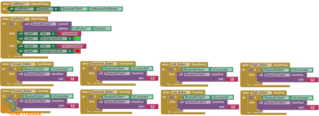
Switch to the Blocks view and add the following logic. These blocks handle Bluetooth device selection, connection, and sending movement commands when buttons are pressed and released.
when ListPicker1.BeforePicking
  set ListPicker1.Elements to BluetoothClient1.AddressesAndNames

when ListPicker1.AfterPicking
  if call BluetoothClient1.Connect address ListPicker1.Selection
    then set Label1.Text to "Connected"
    else set Label1.Text to "Not Connected"

when ButtonForward.TouchDown
  if BluetoothClient1.IsConnected
    call BluetoothClient1.SendText text "F"

when ButtonBackward.TouchDown
  if BluetoothClient1.IsConnected
    call BluetoothClient1.SendText text "B"

when ButtonLeft.TouchDown
  if BluetoothClient1.IsConnected
    call BluetoothClient1.SendText text "L"

when ButtonRight.TouchDown
  if BluetoothClient1.IsConnected
    call BluetoothClient1.SendText text "R"

when ButtonForward.TouchUp
  if BluetoothClient1.IsConnected
    call BluetoothClient1.SendText text "S"

when ButtonBackward.TouchUp
  if BluetoothClient1.IsConnected
    call BluetoothClient1.SendText text "S"

when ButtonLeft.TouchUp
  if BluetoothClient1.IsConnected
    call BluetoothClient1.SendText text "S"

when ButtonRight.TouchUp
  if BluetoothClient1.IsConnected
    call BluetoothClient1.SendText text "S"
Understanding the Block Logic
ListPicker.BeforePicking: When the user taps the ListPicker, it populates the list with all paired Bluetooth device addresses and names from BluetoothClient1.AddressesAndNames.
ListPicker.AfterPicking: After the user selects a device, the app attempts to connect using BluetoothClient1.Connect with the selected address. If successful, Label1.Text is set to “Connected”; otherwise, it shows “Not Connected”. This is why the Label1 component must be present in your interface.
TouchDown events: When the user presses (touches down on) a directional button, the app sends the corresponding command character (F, B, L, or R) via BluetoothClient1.SendText, but only if the Bluetooth connection is active.
TouchUp events: When the user releases (lifts their finger from) any directional button, the app sends “S” (stop). This design means the robot moves only while you hold a button and stops immediately when you release it, giving you precise real-time control.
Step 7: Connecting and Testing the Robot
With the hardware assembled, the code uploaded, and the app installed on your phone, it is time to bring everything together.
Pair the HC-05
Turn on Bluetooth on your Android smartphone and go to Bluetooth settings. Search for new devices. The HC-05 will appear as “HC-05” in the list. Pair with it using the default PIN code 1234 (or 0000 on some modules). You only need to pair once; the phone will remember the device.
Connect and Drive
Open the RobotCarControl app on your phone. Tap the “Select Bluetooth Device” ListPicker and choose the HC-05 from the list. The Label1 should display “Connected”. Now press the directional buttons to drive the car. The robot should move forward, backward, turn left, turn right, and stop when you release the buttons.
How to Test and Tune the OmObi Robot Car
Getting the robot car to drive perfectly often requires a bit of tuning after the initial build. Here are practical steps to dial in the performance of your Arduino Bluetooth car.
Test one direction at a time. Start by sending only the F command and confirming all four wheels spin forward. Then test B, L, and R individually.
Verify left/right motor orientation. If the car veers to one side during forward driving, one motor pair may be wired in reverse. Swap the two wires at the affected motor terminal on the shield.
Reduce speed during first tests. Set setSpeed(120) instead of 255. This gives you more reaction time and prevents crashes during indoor testing.
Fix wrong turning direction. If “Left” turns the car right, swap the left and right motor assignments in the code (change M1/M2 logic to M3/M4 and vice versa), or physically swap the motor wiring.
Improve responsiveness. If the car feels sluggish or delayed, check that the HC-05 baud rate matches the Arduino serial baud rate (9600). Also ensure fresh batteries, as low voltage causes slow motor response.
استكشاف الأخطاء وإصلاحها في المشاكل الشائعة
If your Bluetooth controlled robot car is not working as expected, check the common issues below before starting over. Most problems are caused by simple wiring mistakes or configuration mismatches.
HC-05 Pairs but the Car Does Not Move
The Bluetooth connection is established, but the motors do not respond. Check that the HC-05 TXD pin is connected to Arduino RX (pin 0) and RXD to Arduino TX (pin 1). Also verify that the baud rate in your Arduino code matches the HC-05 default (9600). Make sure the motor shield is properly seated on the Arduino and that the battery pack is connected and turned on.
Arduino Upload Fails (RX/TX Conflict)
If you get upload errors like “avrdude: stk500_getsync(): not in sync”, the HC-05 is likely still connected to pins 0 and 1. Disconnect the HC-05 RX and TX wires, upload the sketch, then reconnect them. This is the most common issue when using hardware serial with a Bluetooth module.
Robot Moves in the Wrong Direction
If forward drives the car backward, swap the two wires for all four motors at the motor shield terminals. If the car turns opposite to the expected direction, swap the left-side and right-side motor connections or adjust the code.
One Side of the Car Does Not Move
Check the wiring on the non-working side. Make sure the motor wires are firmly inserted into the screw terminals and that the terminal screws are tight. Test the motors individually by running only motor1 or motor3 in the code. If a terminal on the shield is damaged, try using a different M-terminal.
App Connects but Buttons Do Nothing
Verify that the app is sending the correct characters (F, B, L, R, S). In MIT App Inventor, make sure the BluetoothClient component is properly linked in the blocks and that SendText uses the exact uppercase characters expected by the Arduino code. Also confirm that Label1 shows “Connected” after pairing.
Motors Are Weak or Inconsistent
Weak motors usually indicate a power problem. Replace the batteries with fresh ones or switch to a higher-capacity battery pack. Four DC motors under load draw significant current, and depleted batteries cannot deliver enough. Also check all power connections for loose wires.
Robot Keeps Moving After Button Release
This means the stop command (S) is not being sent or received when you lift your finger. In the app, make sure every button has both a TouchDown block (to send the movement command) and a TouchUp block (to send “S”). If the TouchUp blocks are missing, the Arduino never receives the stop command.
Battery Power Is Insufficient
If the Arduino resets when motors start or the car behaves erratically, the battery pack cannot supply enough current. Use a pack rated for at least 2A continuous output. Rechargeable NiMH AA batteries or a 2S Li-ion pack with a BMS work well for four-motor robot cars.
الأسئلة الشائعة
هل يمكنني استخدام وحدة HC-06 بدلاً من وحدة HC-05؟
Yes. The HC-06 works as a slave-only Bluetooth module, which is exactly what this project needs. The wiring and baud rate are the same. The only difference is that the HC-06 cannot initiate connections, but since the phone always initiates, this does not matter. See our HC-05 vs. HC-06 comparison for details.
What Bluetooth app can I use to control the robot car?
This tutorial uses a custom app built with MIT App Inventor, which gives you full control over the interface and command mapping. Alternatively, you can use generic Bluetooth serial terminal apps from the Google Play Store, but you will need to type the command characters (F, B, L, R, S) manually instead of pressing buttons.
Can I control the OmObi robot car from an iPhone?
Not directly. The HC-05 uses Bluetooth Classic (SPP), which iOS does not support for third-party apps. To control the car from an iPhone, you would need to replace the HC-05 with a BLE (Bluetooth Low Energy) module like the HM-10 or use an ESP32 with BLE support, and modify the app accordingly.
Why does my Arduino reset when the motors start?
This is almost always a power issue. When all four motors start simultaneously, the current spike can cause the supply voltage to drop below the Arduino minimum, triggering a reset. Use a battery pack with higher current capacity, and make sure the motor power and Arduino power share a common ground but ideally come from a source that can handle the load.
Can I use the Adafruit Motor Shield V2 instead of V1?
Yes, but the code library is different. The V2 shield uses the Adafruit_MotorShield library (I2C-based) instead of AFMotor.h. The wiring and motor terminal layout are similar, but you will need to rewrite the motor initialization and control portions of the code to use the V2 library API.
How far can the Bluetooth connection reach?
The HC-05 has a typical range of about 10 meters (30 feet) in open air. Walls, interference from Wi-Fi routers, and other Bluetooth devices can reduce this range. For most indoor robot car projects, 10 meters is more than enough.
How do I add speed control from the app?
You can add a slider in MIT App Inventor that sends a speed value (for example, 0 to 255) as a separate command. In the Arduino code, read this value and call motorX.setSpeed(value) for all four motors. Use a different command prefix (like “V” followed by the number) to distinguish speed commands from direction commands.
Can I use this project with two motors instead of four?
Yes. For a two-wheel-drive car, connect the two motors to M1 and M3 (or any two terminals, one per side). Remove the unused motor objects from the code or simply leave them defined but unconnected. The turning and driving logic remains the same.
Why does the car only turn in circles?
If the car turns in circles during a forward command, one side of the motors is wired in the reverse direction. Swap the two wires for the motors on the side that is spinning the wrong way at the shield screw terminals.
Do I need to install a special library for the code?
Yes. You need the Adafruit Motor Shield library (AFMotor.h). In the Arduino IDE, go to Sketch > Include Library > Manage Libraries, search for “Adafruit Motor Shield library”, and install it. This library is required for the AF_DCMotor class used in the code.
الموارد والمشاريع القادمة
Now that you have built the OmObi Bluetooth controlled robot car with Arduino, here are related OmArTronics tutorials to continue learning and building more advanced projects:
- HC-05/HC-06 Arduino Bluetooth Module Complete Tutorial – Deep dive into Bluetooth serial communication, LED control, and relay-based lamp control with MIT App Inventor.
- دليل التحكم في محرك التيار المستمر L298N مع أردوينو: دليل التحكم في محرك التيار المستمر – Understand H-bridge motor driving, PWM speed control, and direction logic for DC motors.
- Building an Obstacle-Avoiding Robot Car with Arduino – Add ultrasonic sensors and autonomous navigation to a similar robot car platform.
- Advanced Autonomous and Bluetooth Robot Car with Arduino Mega – Scale up to an Arduino Mega with multiple ultrasonic sensors and combined autonomous and Bluetooth control modes.
- Building a Line Following Robot with KY-033 Sensors – Build a robot that follows lines autonomously using infrared sensors.
- دليل التحكم في محركات المؤازرة باستخدام أردوينو: SG90، PWM، وPCA9685 – Learn servo motor fundamentals for adding steering or a sensor mount to your robot.
- Arduino Programming Basics: Complete Beginner Guide – If you are new to Arduino, start here to learn the IDE, sketch structure, and core concepts.
For further upgrades, consider adding obstacle avoidance with an ultrasonic sensor, a camera module for FPV driving, or switching to an ESP32 for Wi-Fi-based control and longer range.
خاتمة
In this tutorial, you built the OmObi Bluetooth controlled robot car with Arduino, HC-05, and Adafruit Motor Shield from the ground up. You assembled a four-wheel-drive chassis, wired four DC motors through the Adafruit Motor Shield, connected the HC-05 for wireless Bluetooth communication, wrote Arduino code to interpret movement commands, and created a custom Android control app with MIT App Inventor.
This project gives you a solid foundation in motor control, wireless communication, and mobile app development, which are core skills for any robotics enthusiast. From here, you can expand the car with autonomous obstacle avoidance, add speed control via the app, or upgrade to a more powerful Arduino Mega platform with additional sensors.
Happy building! Feel free to ask any questions in the comments section below and explore our other Arduino tutorials for more project inspiration.
قم بتنزيل ملفات الطباعة ثلاثية الأبعاد (STL)
جميع ملفات STL القابلة للطباعة ثلاثية الأبعاد لهذا المشروع متاحة للتنزيل. يمكنك الحصول عليها من متجرنا أو تصفحها على موقع Cults3D.
- متجر أومارترونيكس: قم بتنزيل ملف المشروع من OmArTronics — احصل على حزمة المشروع الكاملة بما في ذلك ملفات STL ومخططات الأسلاك وشفرة المصدر التي يتم تسليمها إلى بريدك الإلكتروني.
- Cults3D: شاهد على موقع Cults3D — تصفح وقم بتنزيل ملفات النماذج ثلاثية الأبعاد على موقع Cults3D.
رأي واحد حول “Building the Bluetooth-Controlled Robot Car OmObi with Arduino, HC-05, and Adafruit Motor Shield”