

📋 Quick Summary
Learn Arduino programming from scratch. This beginner guide covers the Arduino IDE setup, sketch structure with setup() and loop(), core C/C++ concepts (variables, data types, functions, control flow), digital and analog I/O, Serial Monitor debugging, and three hands-on projects: LED blink, button input, and potentiometer-controlled LED brightness.
Want to learn Arduino programming basics but not sure where to start? In fact, you are in the right place. Arduino is the most popular platform for learning electronics and coding, and getting started is easier than you think.
In this complete beginner guide, you will learn everything you need to write, upload, and test your first Arduino programs. We will cover how the Arduino IDE works, what a sketch is, how setup() and loop() control your code, and the essential programming building blocks every beginner needs. By the end, you will have built three working projects and gained the confidence to tackle more advanced tutorials on OmArTronics.
What You Will Learn
By the end of this Arduino basics for beginners guide, you will consequently be able to:
- Install and navigate the Arduino IDE
- Understand what an Arduino sketch is and how .ino files work
- Explain how
setup()andloop()control program flow - Use variables, data types, constants, functions, and comments in your code
- Control digital outputs and read digital and analog inputs
- Use the Serial Monitor for debugging
- Build three hands-on beginner projects: Blink, Button LED, and Analog Reader
- Troubleshoot the most common Arduino errors
What Is an Arduino Sketch?
Before you start writing code, you need to understand what an Arduino sketch is. Essentially, a sketch is the name Arduino uses for a program. In particular, every sketch is saved as a .ino file, which is a plain text file containing your code.
Once you write a sketch and click Upload, the Arduino IDE compiles your code into machine instructions and sends them to the microcontroller on the Arduino board. Subsequently, the board executes those instructions, interacting with hardware components like LEDs, sensors, and motors connected to its pins.
Every Arduino sketch must contain two special functions:
setup() — Runs Once
First, the setup() function runs a single time when the board powers on or resets. Specifically, use it to configure pin modes, initialize serial communication, set starting values, and prepare libraries. In other words, think of it as the preparation step before your main program begins.
loop() — Repeats Forever
Then, the loop() function runs continuously after setup() finishes. In particular, the code inside loop() executes from top to bottom, then starts again from the top, repeating as long as the board has power. As a result, this is where your main program logic goes — reading sensors, controlling outputs, making decisions, and communicating with other devices.
Here is the minimal structure of every Arduino sketch:
void setup() {
  // Initialization code runs once
}

void loop() {
  // Main code runs repeatedly
}
This two-function structure is what makes Arduino programming basics simple to learn. Once you understand setup() and loop(), you can build any project.
Installing the Arduino IDE
The Arduino Integrated Development Environment (IDE) is the free, open-source software you use to write, compile, and upload code to your Arduino board. Moreover, it runs on Windows, macOS, and Linux. Below is how to install it:
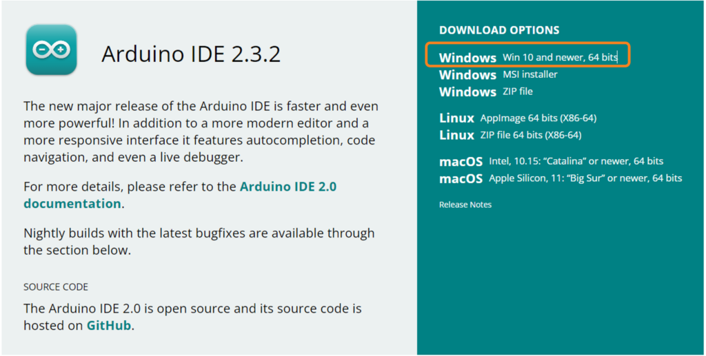
Step 1 — Download: Visit the official Arduino website and download the latest version of the Arduino IDE for your operating system.
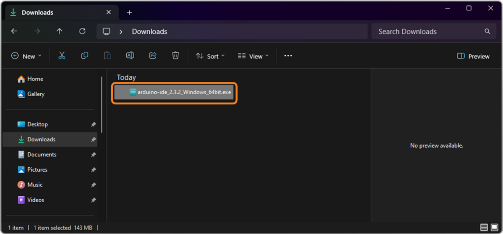
Next, run the installer: Navigate to your Downloads folder and double-click the installer file (for example, arduino-ide_x.x.x_Windows_64bit.exe) to start the setup.
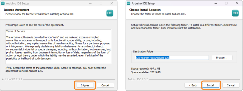
Step 3 — Follow the Wizard: Accept the license agreement and choose the full installation option to include all necessary USB drivers.
Finally, finish the setup: Wait for the progress bar to complete. When the confirmation screen appears, click Finish to launch the Arduino IDE.
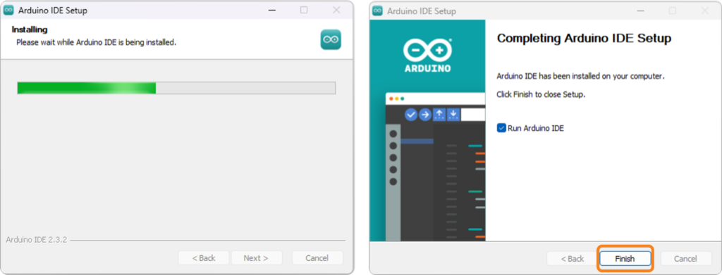
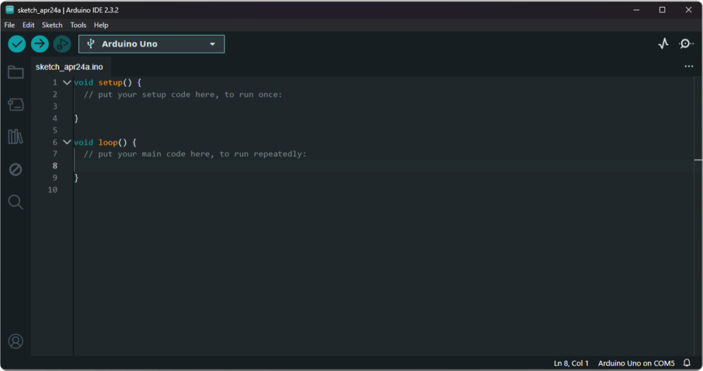
When the IDE opens, you will see a new empty sketch with the setup() and loop() functions already in place. This is your starting point for every Arduino project.
Overview of the Arduino IDE Interface
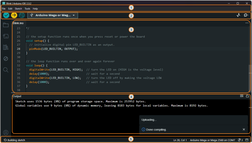
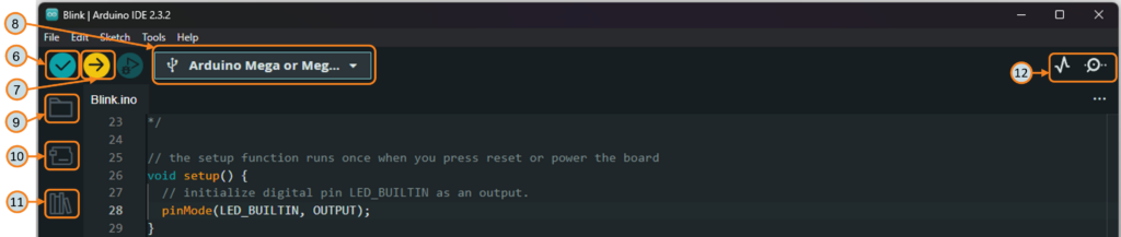
Overall, the Arduino IDE interface is clean and beginner-friendly. The images below show the IDE with numbered labels. Use the following table to identify each element:
| # | Element | What It Does |
|---|---|---|
| ① | Menu Bar | Access file operations, preferences, board settings, and help resources |
| ② | Board & Port Selector | Choose the correct board type (e.g., Arduino Uno) and the COM port it is connected to |
| ③ | Code Editor | The central area where you write and edit your sketch with syntax highlighting |
| ④ | Console / Output Window | Shows compilation messages, errors, and upload progress at the bottom of the IDE |
| ⑤ | Status Bar | Displays the current line number, board name, and connected COM port |
| ⑥ | Verify / Compile Button | Checks your code for errors and compiles it into uploadable format |
| ⑦ | Upload Button | Sends the compiled program to the connected Arduino board |
| ⑨ | Sketchbook | Quick access to all your saved sketches for easy project management |
| ⑪ | Library Manager | Search for and install additional code libraries needed for sensors, displays, and more |
| ⑫ | Serial Monitor Button | Opens the Serial Monitor to view data exchanged between the board and your computer |
Above all, before uploading any sketch, always confirm that the correct board and COM port are selected in the Board & Port Selector. This is the most common source of upload errors for beginners.
Core Arduino Programming Basics
Before building projects, let’s cover the essential Arduino programming basics you will use in nearly every sketch. Furthermore, understanding these building blocks will make every tutorial on OmArTronics easier to follow.
Variables and Data Types
Simply put, a variable is a named container that stores a value in your program. Therefore, you must declare the data type when creating a variable. Here are the most common types:
| Data Type | Description | Example |
|---|---|---|
int | Whole numbers (−32,768 to 32,767) | int speed = 150; |
long | Large whole numbers | long distance = 100000; |
float | Decimal numbers | float temperature = 23.5; |
bool | True or false | bool ledOn = true; |
char | Single character | char grade = 'A'; |
String | Text string | String name = "Arduino"; |
Constants
Use the const keyword to create a value that never changes during program execution. As a result, constants make your code easier to read and safer from accidental changes.
const int LED_PIN = 13;
const float PI_VALUE = 3.14159;
Arduino also has built-in constants like HIGH, LOW, INPUT, OUTPUT, and INPUT_PULLUP that you will use frequently.
Comments
Comments are notes in your code that the compiler ignores. In essence, they help you and others understand what the code does. Use // for single-line comments and /* */ for multi-line comments.
// This is a single-line comment

/* This is a
   multi-line comment */
Functions
A function is a reusable block of code that performs a specific task. You already know setup() and loop(). Additionally, you can create your own custom functions to keep your code organized:
void blinkLED(int pin, int delayTime) {
  digitalWrite(pin, HIGH);
  delay(delayTime);
  digitalWrite(pin, LOW);
  delay(delayTime);
}
Digital Output — digitalWrite()
Digital output lets you turn a pin HIGH (5V) or LOW (0V). To do this, first set the pin as an output in setup(), then control it in loop():
pinMode(13, OUTPUT);      // In setup()
digitalWrite(13, HIGH);   // Turn pin 13 ON
digitalWrite(13, LOW);    // Turn pin 13 OFF
Digital Input — digitalRead()
In contrast to output, digital input reads whether a pin is HIGH or LOW, which is useful for buttons and switches:
pinMode(2, INPUT_PULLUP);           // In setup()
int state = digitalRead(2);         // Read pin 2
When using INPUT_PULLUP, the pin reads HIGH when the button is not pressed and LOW when pressed.
Analog Input — analogRead()
Similarly, Arduino can read analog voltages on pins A0 through A5 and convert them to a value between 0 and 1023. For instance, this is useful for potentiometers, light sensors, and temperature sensors:
int sensorValue = analogRead(A0); // Read analog pin A0
Serial Communication — Serial Monitor Tutorial
Without a doubt, the Serial Monitor is one of the most important debugging tools for Arduino beginners. Specifically, it lets you send data from the board to your computer screen. Initialize it in setup() and print values in loop():
void setup() {
  Serial.begin(9600);           // Start serial at 9600 baud
}

void loop() {
  Serial.println("Hello!");     // Print text to Serial Monitor
  delay(1000);
}
To open it, click the magnifying glass icon in the top right of the Arduino IDE or press Ctrl+Shift+M. Also, make sure the baud rate at the bottom of the Serial Monitor matches the value in Serial.begin().
Project 1: The Classic Blink Sketch (Your Arduino First Sketch)
Without question, the Blink sketch is the classic Arduino first sketch and the starting point for learning Arduino programming basics. In fact, it is the “Hello, World!” of hardware programming. If this sketch works, you know your board, your IDE, and your USB connection are all functioning correctly.
Why Start with Blink?
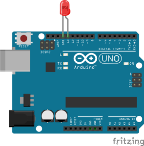
Blink is the simplest possible test. Importantly, it requires no external components because the Arduino Uno has a built-in LED connected to pin 13. In short, by making this LED turn on and off, you verify that you can write code, upload it, and see a physical result in the real world.
Wiring (Optional External LED)
You can run Blink with just the board’s built-in LED on pin 13, but if you want to use an external LED on a breadboard, connect it like this:
- Connect the long leg (anode, +) of the LED to Arduino pin 13 through a 220Ω resistor
- Connect the short leg (cathode, −) of the LED to GND
The Blink Code
/**
 * Author: Omar Draidrya
 * Date: 2024/04/11
 * This code blinks an LED connected to a specified pin on and off with a one-second interval.
 */
// Define the LED pin
const int LED_PIN = 13;
// The setup function runs once when you power up or reset the board
void setup() {
    // Set the LED_PIN as an output
    pinMode(LED_PIN, OUTPUT);
}
// The loop function runs over and over again forever
void loop() {
    digitalWrite(LED_PIN, HIGH); // Turn on the LED
    delay(1000);                 // Wait for a second
    digitalWrite(LED_PIN, LOW);  // Turn off the LED
    delay(1000);                 // Wait for a second
}
Line-by-Line Explanation
const int LED_PIN = 13; — Declares a constant integer for the LED pin number. In addition, using a named constant makes your code easier to update later.
pinMode(LED_PIN, OUTPUT); — Runs once in setup(). Configures pin 13 as a digital output so it can send voltage to the LED.
digitalWrite(LED_PIN, HIGH); — Sets pin 13 to 5V, which turns the LED on.
delay(1000); — Pauses the program for 1000 milliseconds (one second).
digitalWrite(LED_PIN, LOW); — Sets pin 13 to 0V, which turns the LED off.
delay(1000); — Pauses again for one second before the loop repeats.
Upload and Test
To begin, connect the Arduino board to your computer using a USB cable. After that, select the correct board and port in the IDE, then click the Upload button. As soon as the upload finishes, the LED will start blinking — one second on, one second off. Evidently, this blinking is your visual confirmation that your code is working correctly.
Common Blink Mistakes
- Forgetting
pinMode()— Without setting the pin as OUTPUT in setup(), the LED will not turn on - Wrong pin number — Make sure the pin in your code matches the pin your LED is connected to
- Missing delay() — Without delay(), the LED toggles so fast you cannot see it blink
- LED inserted backwards — The long leg (anode) must go to the positive side
Project 2: Read a Push Button and Control an LED
Now that you can blink an LED automatically, it is time to add user input. For this next project, you will read a push button and turn an LED on or off based on whether the button is pressed. This teaches you digital input, one of the most important Arduino programming basics.
Wiring
- Connect one leg of the push button to Arduino pin 2
- Connect the other leg of the push button to GND
- Connect an LED to pin 13 through a 220Ω resistor (or use the built-in LED)
In this case, we will use INPUT_PULLUP mode, which activates the Arduino’s internal pull-up resistor. Consequently, no external resistor is needed for the button.
The Button LED Code
const int BUTTON_PIN = 2;
const int LED_PIN = 13;

void setup() {
  pinMode(BUTTON_PIN, INPUT_PULLUP);  // Button with internal pull-up
  pinMode(LED_PIN, OUTPUT);
}

void loop() {
  int buttonState = digitalRead(BUTTON_PIN);

  if (buttonState == LOW) {       // Button pressed (LOW because of pull-up)
    digitalWrite(LED_PIN, HIGH);  // Turn LED on
  } else {
    digitalWrite(LED_PIN, LOW);   // Turn LED off
  }
}
How It Works
With INPUT_PULLUP, the pin reads HIGH when the button is open (not pressed) and LOW when the button is pressed and connected to GND. The if/else statement checks the button state every loop cycle and controls the LED accordingly. Ultimately, this is how you program Arduino to respond to user input.
Try changing the code to toggle the LED with each press instead of holding it. That exercise will teach you about state tracking and edge detection — important concepts for more advanced motor control projects.
Project 3: Read an Analog Sensor and Print to Serial Monitor
For this third project, you will read an analog value from a potentiometer and print the result to the Serial Monitor. In particular, this is a practical Arduino serial monitor tutorial that teaches you analog input and serial debugging at the same time.
Wiring
- Connect the middle pin of a potentiometer to Arduino pin A0
- Connect one outer pin of the potentiometer to 5V
- Connect the other outer pin to GND
The Analog Reader Code
const int SENSOR_PIN = A0;

void setup() {
  Serial.begin(9600);  // Start serial communication at 9600 baud
}

void loop() {
  int sensorValue = analogRead(SENSOR_PIN);  // Read analog value (0-1023)

  Serial.print("Sensor Value: ");
  Serial.println(sensorValue);  // Print value to Serial Monitor

  delay(250);  // Short delay to keep output readable
}
How It Works
Essentially, the potentiometer acts as a voltage divider. Therefore, as you turn the knob, the voltage on pin A0 changes between 0V and 5V. The analogRead() function converts that voltage into a number between 0 and 1023. As a result, the Serial Monitor then displays the live value so you can see the reading change in real time.
This same technique works for any analog sensor — light sensors, temperature sensors, soil moisture sensors, and more. Once you are comfortable reading analog values, you can move on to more advanced sensor projects like measuring distance with ultrasonic sensors or building a DIY Arduino radar.
Troubleshooting Common Arduino Errors
Even when you understand the Arduino programming basics, every beginner hits errors. Here are the most common problems and how to fix them quickly.
Common Error Reference
| Problem | Cause | Fix |
|---|---|---|
| Wrong board selected | The IDE is set to a different board than the one connected | Go to Board & Port Selector and choose the correct board (e.g., Arduino Uno) |
| Wrong COM port | The IDE is pointing to the wrong serial port | Select the correct COM port from the Board & Port Selector — unplug and replug the USB cable to identify the right port |
| Bad USB cable | Some USB cables are charge-only and cannot transfer data | Use a USB cable that supports data transfer — try a different cable if the board is not detected |
| Compile errors | Syntax mistakes in your code (missing semicolons, brackets, typos) | Read the orange error message in the console — it shows the line number and type of error |
| Upload failed | Board not responding or port blocked by another program | Close the Serial Monitor if open, press the reset button on the board, and try uploading again |
| Board not detected | Missing USB drivers or faulty connection | Reinstall the Arduino IDE with drivers, try a different USB port, or install CH340 drivers for clone boards |
Code and Output Errors
| Problem | Cause | Fix |
|---|---|---|
| Serial Monitor shows garbage | Baud rate mismatch between code and Serial Monitor | Make sure the baud rate in Serial.begin() matches the dropdown at the bottom of the Serial Monitor |
| Serial Monitor is blank | Serial not initialized or wrong port selected | Verify that Serial.begin() is in setup() and the correct board/port is selected |
| LED does not light up | LED inserted backwards or missing resistor | Check LED polarity (long leg to positive) and ensure a 220Ω resistor is in the circuit |
| “avrdude” error on upload | Communication failure between the IDE and the board | Check the USB connection, select the correct board/port, and press reset before uploading |
Still Stuck?
If you are still stuck, double-check your wiring, restart the Arduino IDE, and try a different USB port. Most beginner issues come down to the board, port, or cable selection.
Frequently Asked Questions (FAQ)
In short, Arduino programming means writing code (called a sketch) in a simplified version of C/C++ and uploading it to an Arduino board using the Arduino IDE. The board then runs your code to control LEDs, motors, sensors, and other electronic components.
Primarily, Arduino uses a simplified version of C/C++. However, you do not need to learn full C++ to get started. The Arduino framework provides beginner-friendly functions like digitalWrite(), analogRead(), and Serial.println() that hide much of the complexity.
The setup() function runs once when the board powers on or resets. It is used for initialization like setting pin modes and starting serial communication. The loop() function runs continuously after setup() finishes, executing your main program logic over and over.
No. Fortunately, Arduino is designed for beginners with zero programming experience. Instead, start with simple projects like Blink, then gradually learn new concepts like variables, conditionals, and sensor reading as you build more projects.
Simply put, the Arduino IDE (Integrated Development Environment) is the free software application where you write, compile, and upload sketches to your Arduino board. It is available for Windows, macOS, and Linux and includes a code editor, compiler, uploader, and Serial Monitor.
First, connect your Arduino to your computer with a USB cable, then select the correct board and COM port in the Arduino IDE, write or open your sketch, and finally click the Upload button (right arrow icon). The IDE compiles and transfers the program to the board automatically.
Common causes include a charge-only USB cable (use a data cable instead), missing USB drivers, a faulty USB port, or a damaged board. To fix this, try a different cable, reinstall drivers, or try another USB port. In addition, clone boards often need CH340 or CP2102 drivers installed separately.
The Serial Monitor displays data sent from your Arduino to the computer via the USB connection. Primarily, it is used for debugging — printing variable values, sensor readings, and status messages so you can see what your program is doing in real time.
Yes. Once a sketch is uploaded, the Arduino runs independently using any 5V–12V power source. However, you need a computer to write and upload new sketches. You can also use the Arduino Cloud IDE for browser-based programming.
After mastering the basics, explore sensor integration, servo motor control, Bluetooth communication, LCD displays, and robotics. OmArTronics has step-by-step tutorials for all of these topics, from building a line-following robot to building a 6-DOF robotic arm.
Yes. Arduino is one of the best platforms for STEM education. The combination of simple programming syntax, hands-on projects, and visible results (blinking LEDs, moving motors) makes it ideal for students of all ages learning electronics and coding.
What to Learn Next After Arduino Programming Basics
Congratulations — at this point, you now understand the Arduino programming basics that every maker needs. You know what a sketch is, how setup() and loop() work, and how to use variables, digital I/O, analog input, and serial communication. Moreover, you have built three real projects and learned how to troubleshoot common errors.
Of course, this is just the beginning. Here are some recommended OmArTronics tutorials to continue your learning path:
- Microcontroller Programming Types Explained — Explore all major approaches to programming microcontrollers, from graphical tools and C/C++ to Python and professional IDEs.
- Arduino Servo Control Guide: SG90, PWM, and PCA9685 — Learn to control servo motors for robotic arms and pan-tilt systems
- Arduino Bluetooth Module Tutorial (HC-05/HC-06) — Add wireless Bluetooth control to your projects
- Ultrasonic Sensor Distance Measurement — Measure distance without contact using the HC-SR04 sensor
- Controlling DC Motors with L298N and Motor Shield — Drive DC motors for robot cars and mobile platforms
- Building a Line Following Robot for Beginners — Combine sensors and motors into your first autonomous robot
- DIY 6-DOF Robotic Arm with Bluetooth Control — An advanced project that brings together everything you have learned
Above all, keep building, keep experimenting, and do not be afraid to make mistakes. After all, every error is a learning opportunity, and every project makes you a better maker. See you in the next tutorial!
2 thoughts on “Arduino Programming Basics: Complete Beginner Guide to Your First Sketch”