You are currently viewing Building a Line-Following Robot: From 3D Design to Implementation with KY-033 and TCS34725 Sensors
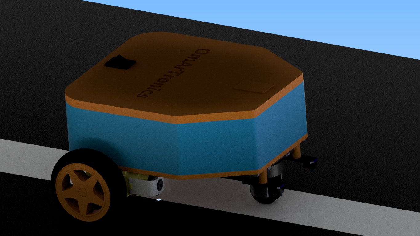
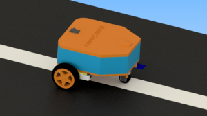
This is the 3D-rendered design of the Arduino path-following robot equipped with TCS34725 and KY-033 sensors for accurate line tracking.

Building a Line-Following Robot: From 3D Design to Implementation with KY-033 and TCS34725 Sensors

In this tutorial, we’ll guide you step-by-step to design, 3D print, assemble, and program a line-following robot using TCS34725 RGB and KY-033 IR sensors. This robot can autonomously follow a predefined line on a contrasting surface, making it a great hands-on project for learning robotics, sensor integration, and Arduino programming.
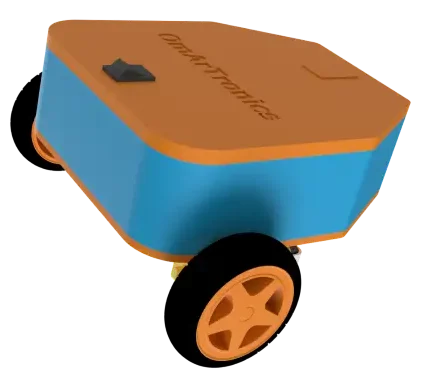
A 3D-rendered line-following robot designed with an orange and blue chassis, featuring OmArTronics branding, two wheels, and a support caster wheel, suitable for DIY robotics projects.

Whether you choose the TCS34725 or KY-033 sensor setup, this project introduces essential skills in 3D design, assembly, and control programming. By the end, you’ll have a functional line-following robot that’s both fun and educational to build! 

المكونات المطلوبة:

3D-Printed Parts

  • Chassis: Houses the motors, sensors, and Arduino board.
  • Sensor Holder: Aligns the sensors for precise line detection.
  • Arduino Holder: Mounts the Arduino securely to the chassis.

Motors and Wheels

  • 2 DC Motors with Gearboxes: Drive the robot.
  • 2 Wheels: Provide mobility.
  • 1 Support Wheel: Balances the robot for smooth movement.

Electronics

  • أردوينو أونو: Microcontroller for programming and control.
  • Arduino Motor Shield Rev3: Drives the motors and distributes power.
  • KY-033 Line-Tracking Sensors: Detect the black line using IR.
  • TCS34725 RGB Light Sensor: Measures light intensity to differentiate between colors.

Accessories

  • Jumper Wires: For connecting components.
  • Screws and Inserts: To securely mount parts.
  • Battery (e.g., 7.4V LiPo): Powers the robot.
  • Power Switch: Optional, for easy on/off control.

Step 1: Designing the Robot in Autodesk Inventor

We started by designing the robot in Autodesk Inventor. The design ensures all components fit securely while maintaining a lightweight and compact structure. Key features include:

  1. Chassis: A sturdy base for mounting the motors, sensors, and Arduino.
  2. Sensor Holder: Holds the KY-033 or TCS34725 sensor for precise line detection.
  3. Arduino Holder: Provides easy access to the Arduino for programming and wiring.

You can download the STL files for these 3D-printed parts from Cults3D.

Step 2: 3D Printing the Components

After finalizing the design, we used a Creality Ender 3 printer to 3D print the components. Materials like PLA or ABS are recommended for durability. Ensure the parts are cleaned and prepared before assembly.

Step 3: Assembling the Robot

1. Mounting the Motors and Wheels

  • Secure the motors to the chassis using screws and inserts.
  • Attach the wheels to the motor shafts and ensure smooth rotation.
  • Mount the support wheel at the rear for balance.

2. Installing the Electronics

  • Mount the Arduino Uno and Motor Shield to the chassis.
  • Attach the sensors to the sensor holder.
  • Connect the Battery and secure all components.

3. Wiring the Components

  • Wire the motors to the Motor Shield.
  • Connect the sensors to the Arduino pins.
  • Ensure the battery is safely connected and add a switch for convenience.
Step 4: Programming the Line Following Robot

KY-033 Sensors Approach

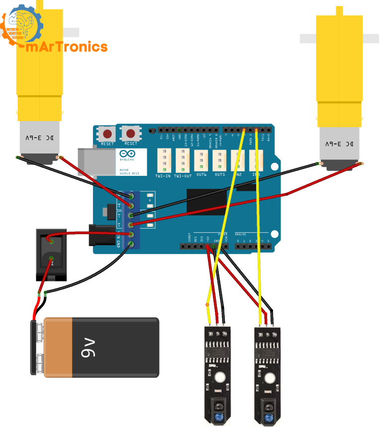
The KY-033 sensors are used to detect the black line on a white surface using IR light. The logic behind the approach is straightforward:

  • Left sensor on the line: The robot turns right to adjust back to the path.
  • Right sensor on the line: The robot turns left to adjust back to the path.
  • Both sensors on the line: The robot moves straight.
  • Both sensors off the line: The robot rotates in place to search for the path.

Here’s the complete code for the KY-033 sensors approach:
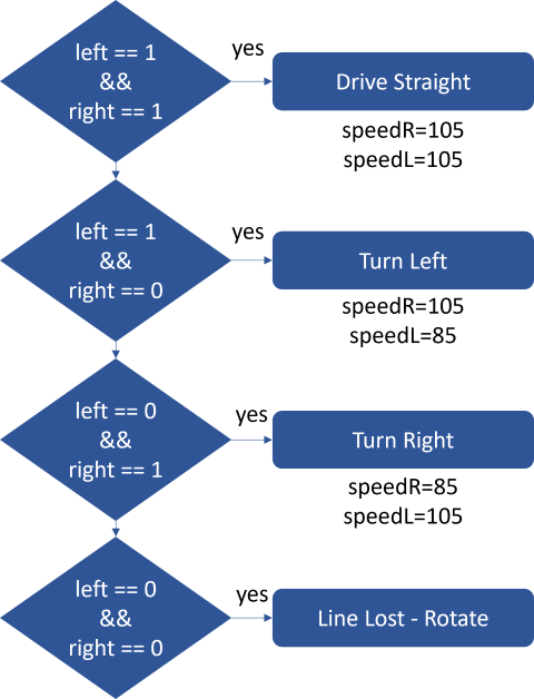
Wiring diagram for a line-following robot using Arduino Uno, motor shield, DC motors, sensors, and a 9V battery.
/**
 * Author: Omar Draidrya
 * Date: 2024/12/06
 * This code controls a Bluetooth robot with an integrated robotic arm.
 */

// Motor control pins
#define DIR_L 12  // Left motor direction
#define DIR_R 13  // Right motor direction
#define PWM_L 3   // Left motor speed (PWM)
#define PWM_R 11  // Right motor speed (PWM)

// Sensor pins
int sensorLeft = 2;    // Left sensor
int sensorRight = 4;   // Right sensor

void setup() {
  // Configure motor pins as outputs
  pinMode(DIR_L, OUTPUT);
  pinMode(DIR_R, OUTPUT);
  pinMode(PWM_L, OUTPUT);
  pinMode(PWM_R, OUTPUT);

  // Configure sensor pins as inputs
  pinMode(sensorLeft, INPUT);
  pinMode(sensorRight, INPUT);

  // Serial communication for debugging
  Serial.begin(9600);
}

void loop() {
  // Read sensor values
  int left = digitalRead(sensorLeft);
  int right = digitalRead(sensorRight);

  // Output sensor data (debugging)
  Serial.print("Sensor Left: ");
  Serial.print(left);
  Serial.print("  |  Sensor Right: ");
  Serial.println(right);

  // Control logic
  if (left == 1 && right == 1) {
    // Drive straight
    controlMotors(HIGH, HIGH, 105, 105);
  } else if (left == 1 && right == 0) {
    // Turn left
    controlMotors(HIGH, LOW, 105, 85);
  } else if (left == 0 && right == 1) {
    // Turn right
    controlMotors(LOW, HIGH, 85, 105);
  } else {
    // Line lost – stop motors
    // Rotate in place to find the line
    controlMotors(HIGH, LOW, 70, 70);  // Left motor forward, right motor backward
    // delay(500);  // Brief rotation
    // controlMotors(LOW, LOW, 0, 0);
  }
}

// Function to control motors
void controlMotors(int directionL, int directionR, int speedL, int speedR) {
  digitalWrite(DIR_L, directionL);
  digitalWrite(DIR_R, directionR);
  analogWrite(PWM_L, speedL);
  analogWrite(PWM_R, speedR);
}


Here’s a detailed breakdown of the code, explaining each section to help you understand how the KY-033 sensor-based line-following robot operates.

1. Motor Control Pins

// Motor control pins
#define DIR_L 12  // Left motor direction
#define DIR_R 13  // Right motor direction
#define PWM_L 3   // Left motor speed (PWM)
#define PWM_R 11  // Right motor speed (PWM)
    
  • These pins are used to control the direction and speed of the motors.
    • DIR_A and DIR_B determine the direction of the motors.
    • PWM_A and PWM_B control the speed using Pulse Width Modulation (PWM).

2. Sensor Pins

int sensorLeft = 2;    // Left sensor
int sensorRight = 4;   // Right sensor
    
  • The KY-033 sensors are connected to digital pins 2 and 4 on the Arduino.
  • These sensors detect the line by reading either HIGH (1) or LOW (0).

3. setup() Function

void setup() {
  // Configure motor pins as outputs
  pinMode(DIR_L, OUTPUT);
  pinMode(DIR_R, OUTPUT);
  pinMode(PWM_L, OUTPUT);
  pinMode(PWM_R, OUTPUT);

  // Configure sensor pins as inputs
  pinMode(sensorLeft, INPUT);
  pinMode(sensorRight, INPUT);

  // Serial communication for debugging
  Serial.begin(9600);
}
    
  • Configures the motor control pins as outputs and the sensor pins as inputs.
  • Initializes serial communication for debugging purposes.

4. loop() Function

int left = digitalRead(sensorLeft);
int right = digitalRead(sensorRight);
    
  • Reads the values from the KY-033 sensors.
    • 1 indicates the sensor detects a line (black surface).
    • 0 indicates the sensor does not detect a line (white surface).

5. Debugging Output

Serial.print("Sensor Left: ");
Serial.print(left);
Serial.print("  |  Sensor Right: ");
Serial.println(right);
    
  • Prints the sensor readings to the serial monitor for real-time debugging.

6. Control Logic

if (left == 1 && right == 1) {
  controlMotors(HIGH, HIGH, 105, 105);
} else if (left == 1 && right == 0) {
  controlMotors(HIGH, LOW, 105, 85);
} else if (left == 0 && right == 1) {
  controlMotors(LOW, HIGH, 85, 105);
} else {
  controlMotors(HIGH, LOW, 70, 70);
}

    
  • This block controls the robot’s movement based on sensor readings:
    • Both sensors detect the line (1, 1): Move straight.
    • Left sensor detects the line, right sensor does not (1, 0): Turn left.
    • Right sensor detects the line, left sensor does not (0, 1): Turn right.
    • Both sensors do not detect the line (0, 0): Rotate to search for the line.

7. Motor Control Function

// Function to control motors
void controlMotors(int directionL, int directionR, int speedL, int speedR) {
  digitalWrite(DIR_L, directionL);
  digitalWrite(DIR_R, directionR);
  analogWrite(PWM_L, speedL);
  analogWrite(PWM_R, speedR);
}
    
  • This function sets the motor direction and speed using the defined pins.

This implementation ensures accurate line-following behavior using KY-033 sensors. Next, we’ll move on to the TCS34725 sensor approach and explain the corresponding code in a similar manner.

TCS34725 Sensor Approach

The TCS34725 RGB sensor is highly effective for distinguishing the black line from the white background due to its ability to measure light intensity across various wavelengths. This approach includes a calibration phase and uses a PID controller to ensure smooth and accurate path following.

Understanding PID Control Fully in the Context of Line Following

The PID (Proportional-Integral-Derivative) controller is a fundamental concept in control systems, designed to adjust outputs based on feedback from a process variable. In the context of the line-following robot, PID ensures dynamic control of motor speeds, enabling precise and smooth path following.

Diagram illustrating a PID feedback control loop with setpoint, controller, plant, and disturbances.

Components of the PID Controller

  1. Proportional (P) Component

    • Purpose: Reacts immediately to the error.
    • Equation:
      y(t) = Kp * e(t)
    • How it works:
      The proportional term multiplies the current error (e) by a proportional gain (Kp). This provides a correction that is directly proportional to the deviation from the desired position, such as the center of the line.
    • Effect:
      • Quick responsiveness to errors.
      • Larger Kp values result in faster reactions but can cause overshooting or instability.
    • Example in Line Following:
      If the robot veers off the line, the proportional component immediately adjusts motor speeds to steer it back.
  2. Integral (I) Component

    • Purpose: Compensates for accumulated errors over time.
    • Equation:
      y(t) = Ki * ∫e(t) dt
    • How it works:
      The integral term sums the error over time and multiplies it by the integral gain (Ki). This helps to correct long-term drift caused by persistent small errors.
    • Effect:
      • Eliminates steady-state error.
      • Slower to react compared to the proportional component.
    • Example in Line Following:
      If the robot consistently drifts to one side, the integral component adjusts the motors to correct the bias over time.
  3. Derivative (D) Component (optional for this project)

    • Purpose: Reacts to the rate of change of the error.
    • Equation:
      y(t) = Kd * (de(t)/dt)
    • How it works:
      The derivative term predicts future errors based on the rate at which the error changes and multiplies this rate by the derivative gain (Kd).
    • Effect:
      • Reduces oscillations and improves stability.
      • Particularly useful for systems experiencing rapid changes.
    • Example in Line Following:
      If the robot oscillates around the line, the derivative component stabilizes it by reducing abrupt motor speed changes.

Combining P, I, and D in a PID Controller

A PID controller combines these three components to provide precise and stable control. The combined equation is:

y(t) = Kp * e(t) + Ki * ∫e(t) dt + Kd * (de(t)/dt)

How it applies to Line Following:

  • The proportional term reacts immediately to how far the robot is from the line.
  • The integral term addresses consistent drift over time.
  • The derivative term dampens oscillations and stabilizes movement.

Dynamic Error Correction with PID

  1. Error Calculation:

    • The error (e) is the difference between the sensor reading and the threshold (middle value).
    • This error drives the PID calculations.
  2. Correction Value (y):

    • The PID controller calculates y to determine how much to adjust motor speeds:
      • speedLeft = baseSpeed + y
      • speedRight = baseSpeed - y
  3. Motor Speed Adjustment:

    • Motor speeds are adjusted dynamically based on the correction value to maintain the robot on the line.

Advantages of Using PID in Line Following

  • Precision: Keeps the robot accurately centered on the line, even in curves.
  • Smooth Movements: Avoids jerky or abrupt adjustments by balancing the contributions of P, I, and D.
  • Disturbance Rejection: Handles changes in surface reflectivity or motor inconsistencies.
  • Adaptability: Can be tuned for different track layouts or robot configurations.

Practical Tuning of PID

  1. Start with Proportional Gain (Kp):

    • Gradually increase Kp until the robot begins to follow the line effectively.
    • Monitor for overshooting or oscillations.
  2. Add Integral Gain (Ki):

    • Introduce Ki to address steady-state errors (e.g., consistent drift).
    • Avoid excessive Ki to prevent instability or oscillations.
  3. Adjust Derivative Gain (Kd):

    • If necessary, use Kd to stabilize movements and reduce oscillations.
    • Avoid setting Kd too high, as it can make the robot sluggish.

Complete Code for TCS34725 Sensor with PID:

/**
 * Author: Omar Draidrya
 * Date: 2024/12/06
 * This code controls a Bluetooth robot with an integrated robotic arm.
 */

#include <Wire.h>
#include <AFMotor.h>

// Initialize TCS34725 sensor
Adafruit_TCS34725 tcs = Adafruit_TCS34725(TCS34725_INTEGRATIONTIME_2_4MS, TCS34725_GAIN_4X);

// Motor control pins
#define DIR_A 12
#define DIR_B 13
#define PWM_A 3
#define PWM_B 11

// PID parameters
float Kp = 27.0;  // Proportional gain
float Ki = 0.5;   // Integral gain
float Kd = 2.5;   // Derivative gain
int baseSpeed = 55;  // Base speed

// Middle value for black/white
int middleValue = 3; // Adjusted based on measured values

// Global variables for PID
float error = 0, previousError = 0, sumError = 0;

void setup() {
  Serial.begin(9600);

  // Initialize TCS34725 sensor
  if (!tcs.begin()) {
    Serial.println("TCS34725 not detected!");
    while (1);
  }
  Serial.println("TCS34725 detected!");

  // Configure pins
  pinMode(DIR_A, OUTPUT);
  pinMode(DIR_B, OUTPUT);
  pinMode(PWM_A, OUTPUT);
  pinMode(PWM_B, OUTPUT);

  // Perform calibration
  calibrateSensor();
}

void loop() {
  uint16_t r, g, b, c;
  tcs.getRawData(&r, &g, &b, &c);

  // Calculate error
  error = (float)c - middleValue;

  // PID calculation
  sumError += error;
  sumError = constrain(sumError, -4, 4); // Limit integral component

  if (abs(error) < 0.5) {
    sumError = 0; // Reset for small errors
  }

  float differential = error - previousError;
  float correction = Kp * error + Ki * sumError + Kd * differential;
  previousError = error;

  // Adjust speed
  int speedLeft = baseSpeed + (int)correction;
  int speedRight = baseSpeed - (int)correction;

  speedLeft = constrain(speedLeft, 20, 255);
  speedRight = constrain(speedRight, 20, 255);

  controlMotors(speedLeft, speedRight);
}

void calibrateSensor() {
  uint16_t r, g, b, c;

  // Measure dark area
  Serial.println("Measuring dark area...");
  controlMotors(-85, 85); // Slightly turn left
  delay(350);
  tcs.getRawData(&r, &g, &b, &c);
  int blackValue = c;
  Serial.print("Black Value: ");
  Serial.println(blackValue);

  // Measure bright area
  Serial.println("Measuring bright area...");
  controlMotors(85, -85); // Slightly turn right
  delay(700);
  tcs.getRawData(&r, &g, &b, &c);
  int whiteValue = c;
  Serial.print("White Value: ");
  Serial.println(whiteValue);

  // Calculate middle value
  middleValue = (blackValue + whiteValue) / 2;
  Serial.print("Middle Value: ");
  Serial.println(middleValue);

  // Stop motors
  controlMotors(0, 0);
}

void controlMotors(int speedLeft, int speedRight) {
  if (speedLeft >= 0) {
    digitalWrite(DIR_A, HIGH);
  } else {
    digitalWrite(DIR_A, LOW);
    speedLeft = abs(speedLeft);
  }

  if (speedRight >= 0) {
    digitalWrite(DIR_B, HIGH);
  } else {
    digitalWrite(DIR_B, LOW);
    speedRight = abs(speedRight);
  }

  analogWrite(PWM_A, speedLeft);
  analogWrite(PWM_B, speedRight);
}
    

Here’s a detailed breakdown of the code, explaining each section to understand how the TCS34725 sensor-based line-following robot operates:

1. Sensor Initialization

Adafruit_TCS34725 tcs = Adafruit_TCS34725(TCS34725_INTEGRATIONTIME_2_4MS, TCS34725_GAIN_4X);
    
  • The TCS34725 sensor is initialized with a short integration time and moderate gain to optimize light intensity readings for a line-following application.

2. Motor Control Pins

#define DIR_A 12
#define DIR_B 13
#define PWM_A 3
#define PWM_B 11
    
  • DIR_A and DIR_B: Control the direction of the motors.
  • PWM_A and PWM_B: Control the speed of the motors using Pulse Width Modulation (PWM).

3. Calibration Function

void calibrateSensor() {
  // Measures the light intensity for black and white areas.
  // Calculates the middle value (threshold) as the average of the two.
}
    
  • The robot rotates slightly to measure the black (dark) and white (bright) areas.
  • The middleValue is calculated and used as the threshold for distinguishing between the black line and the white surface.

4. Main Loop

void loop() {
  uint16_t r, g, b, c;
  tcs.getRawData(&r, &g, &b, &c);
  
  // Reads the light intensity from the sensor.
  // Calculates error and adjusts motor speeds using PID control.
}
    
  • The light intensity (c) is read from the TCS34725 sensor.
  • PID calculations ensure smooth and accurate adjustments to keep the robot on track.

5. PID Control

float correction = Kp * error + Ki * sumError + Kd * differential;
    
  • Proportional (Kp): Corrects based on the current error.
  • Integral (Ki): Accounts for accumulated error over time.
  • Derivative (Kd): Predicts and responds to changes in error.

6. Motor Control Function

void controlMotors(int speedLeft, int speedRight) {
  // Adjusts motor direction and speed based on the calculated correction.
}
    
  • Controls the direction and speed of each motor to ensure smooth movement along the line.

Step 5: Testing the Line-Following Robot

To test the functionality of the robot, a 50mm wide white adhesive tape was placed on a dark surface, forming a curvy line. This setup simulates a typical track for a line-following robot. The testing process was conducted using two different sensor configurations:

1. Testing with KY-033 Sensors

  • The robot was started directly on the white line with both KY-033 sensors positioned over the tape.
  • The robot’s behavior was monitored as it followed the curvy track.
  • Adjustments to the code (e.g., motor speed or delay) were made as necessary to ensure smooth and accurate line tracking.

2. Testing with the TCS34725 RGB Sensor

  • The robot was placed at the left edge of the white tape, with the TCS34725 sensor positioned near the line.
  • The robot performed an automatic calibration by measuring light intensity in two key areas:
    • Dark Area: The robot slightly rotated to measure the dark background.
    • Bright Area: The robot slightly rotated in the opposite direction to measure the white tape.
  • After calculating the middle value as the threshold, the robot began following the line. The PID controller was used to ensure smooth and precise adjustments while navigating curves.

omartronics

مرحبًا بكم في OmArTronics، مركز عشاق التكنولوجيا والعقول المبدعة! اسمي عمر، مؤسس هذا الموقع الإلكتروني وقناة اليوتيوب، وأنا مهندس شغوف ذو خلفية في الهندسة الكهربائية والميكانيكية، وأتابع حاليًا دراسة الماجستير في الميكاترونيكس في ألمانيا.

اترك تعليقاً