
📋 Quick Summary
In this tutorial, you will learn how to build a line-following robot using two KY-033 infrared sensors, an Arduino Uno, and an Adafruit Motor Shield. You will also 3D-print a custom chassis, wire everything up, and write threshold-based steering logic. Because of that, it is a solid first line-follower project before moving on to PID control.
In this KY-033 line following robot Arduino tutorial, you will design, 3D-print, assemble, wire, and program a line-following robot from scratch. The robot uses two KY-033 infrared line-tracking sensors and an Arduino Uno with a motor shield to follow a white line on a dark surface. Because of this, it is a great project if you want to get your hands dirty with robotics, sensors, and Arduino programming.
In particular, this project focuses on the KY-033 sensor setup and covers 3D design, mechanical assembly, wiring, and control programming. By the end of this project, you will have a working Arduino line tracking robot and enough experience to tackle more advanced builds.
Next step: Once you have completed this beginner build, continue with the advanced line following robot tutorial using the TCS34725 RGB sensor and PID control for better precision and smoother tracking on complex tracks.
What You Will Learn
By completing this KY-033 line follower tutorial, you will learn:
- First, how the KY-033 infrared sensors detect a line on the ground and then output digital signals to the Arduino
- Second, how the Arduino Uno and Motor Shield Rev3 work together to drive two DC motors
- Third, how the robot uses left and right sensor readings to decide whether to go straight, turn left, turn right, or search for the line
- How to design, 3D-print, and assemble the robot chassis and component holders
- How to wire all electronics including motors, sensors, and battery
- How to upload and then understand the complete Arduino line following code
- How to test and tune the robot for stable, reliable line following
How the Robot Works
Before we start building, it helps to understand how this line following robot Arduino project works at a high level. Basically, the robot uses differential steering and infrared line detection.
Arduino Uno (The Brain)
The Arduino Uno is the microcontroller that reads the sensor inputs, runs the decision logic, and sends motor control signals. If you are new to Arduino, the Arduino programming basics tutorial on OmArTronics would also be a good place to start.
Arduino Motor Shield Rev3 (The Motor Driver)
The Motor Shield sits on top of the Arduino Uno and handles the power needed to drive the two DC motors. Since it handles power separately, it lets the Arduino control each motor’s direction and speed independently through direction pins and PWM (pulse width modulation) signals. For more detail on motor driving concepts, also see the L298N motor driver guide on OmArTronics.
Two KY-033 Line-Tracking Sensors (The Eyes)
Each KY-033 sensor module has an infrared LED and a photodiode. The IR LED shines light downward onto the surface. A white or light-colored surface reflects more infrared light back to the sensor, while a dark surface absorbs it. The sensor outputs a digital HIGH (1) when it detects a reflective (light) surface and a digital LOW (0) when it detects a non-reflective (dark) surface. Because this project follows a white line on a dark background, the sensors read HIGH when they are over the line.
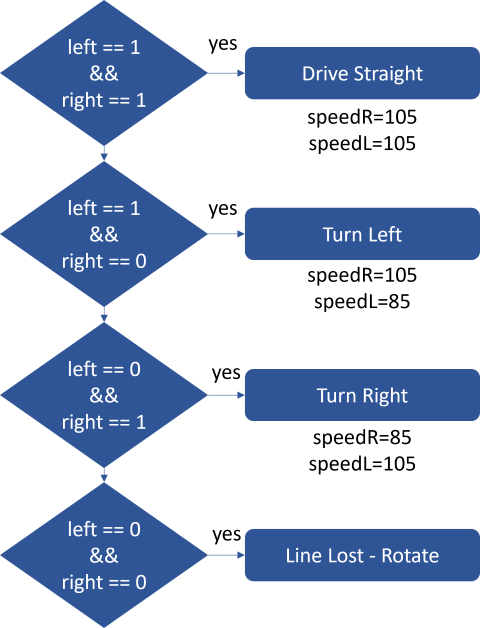
Steering Logic
The robot has two independently driven wheels, one on each side, plus a passive caster wheel at the rear. By varying the speed and direction of the left and right motors based on the two sensor readings, the robot steers itself along the line:
- Both sensors on the line (HIGH, HIGH): As a result, the robot drives straight forward.
- Left sensor on the line, right sensor off (HIGH, LOW): Because the robot has drifted right, it turns left to correct.
- Right sensor on the line, left sensor off (LOW, HIGH): Because the robot has drifted left, it turns right to correct.
- Both sensors off the line (LOW, LOW): The line is lost, so the robot rotates in place to search for the line.
In practice, this approach works well for gentle curves and straight segments. However, for sharper turns and smoother control, the TCS34725 + PID version is a good next step.
Bill of Materials
Here is the complete list of components for this KY-033 line following robot. In fact, most of these parts are common Arduino starter kit components.
| Component | Qty | Required | Purpose | Notes |
|---|---|---|---|---|
| Arduino Uno | 1 | Yes | Microcontroller for control logic | Any Uno-compatible board works |
| Arduino Motor Shield Rev3 | 1 | Yes | Drives the DC motors and distributes power | Stacks directly on the Uno |
| KY-033 Line-Tracking Sensor | 2 | Yes | Detects the line using infrared reflection | Adjustable sensitivity via onboard potentiometer |
| DC Motor with Gearbox | 2 | Yes | Drives the left and right wheels | Standard 3-6V hobby gearmotor |
| Wheels | 2 | Yes | Provide mobility | Must fit the motor shaft |
| Support Caster Wheel | 1 | Yes | Rear balance point | Ball caster or small swivel wheel |
| 3D-Printed Chassis | 1 | Yes | Main body housing all components | STL files available on Cults3D and OmArTronics Shop |
| 3D-Printed Sensor Holder | 1 | Yes | Positions KY-033 sensors at correct height | Designed for this project |
| 3D-Printed Arduino Holder | 1 | Yes | Mounts the Arduino and shield securely | Designed for this project |
| Jumper Wires | Several | Yes | Connect sensors and motors to the Arduino | Pin-to-socket type recommended |
| Screws and Threaded Inserts | Several | Yes | Secure motors and holders to chassis | M3 screws typical |
| Battery (7.4V LiPo or 9V) | 1 | Yes | Powers the Arduino and motors | 7.4V LiPo recommended for consistent power |
| Power Switch | 1 | Optional | Easy on/off control | Inline toggle switch on battery wire |
Step 1: Designing the Robot in Autodesk Inventor
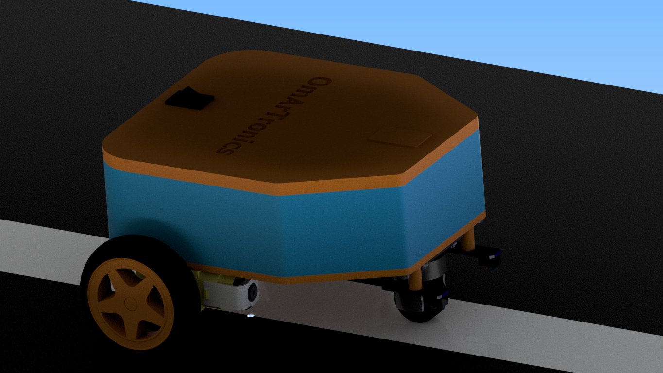
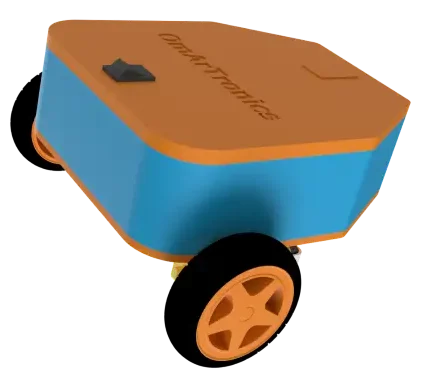
First, we designed the robot chassis and component holders in Autodesk Inventor so all parts fit together securely in a compact layout. Overall, the design has three 3D-printed parts:
- Chassis: The main base that holds the DC motors, sensors, Arduino board, and battery.
- Sensor Holder: Positions the two KY-033 sensors at the correct height and spacing, so that line detection is accurate.
- Arduino Holder: Mounts the Arduino Uno and Motor Shield to the chassis with ports accessible for programming and wiring.
You can download the STL files for all 3D-printed parts from Cults3D or from our OmArTronics Shop. If you are new to 3D printing, the Introduction to 3D Printing guide on OmArTronics is a good starting point.
Step 2: 3D Printing the Components
Once the design was finalized, we 3D-printed the components on a Creality Ender 3. In general, PLA works well for this build because it prints easily and is strong enough for the job. However, ABS is an alternative if you need higher heat resistance. Once printing is done, clean up any support material, remove rough edges, and also check that all screw holes and mounting features are the right size before you start assembly.
Step 3: Assembling the Robot
Once you have all your printed and purchased parts ready, assemble the KY-033 line following robot in this order.
3.1 Mounting the Motors and Wheels
- First, secure the two DC motors to the chassis using screws and threaded inserts. Also make sure each motor sits firmly and is aligned.
- Then press-fit the wheels onto the motor shafts and check that they rotate freely without wobbling.
- After that, mount the support caster wheel at the rear of the chassis for balance.
3.2 Installing the Electronics
- First, attach the Arduino Uno to the Arduino Holder and mount it on the chassis.
- Then stack the Motor Shield Rev3 onto the Arduino Uno.
- Next, mount the two KY-033 sensors into the Sensor Holder, then attach the holder to the front underside of the chassis. Because the sensors need to see the surface, they should point downward toward the ground.
- Finally, position the battery securely inside the chassis.
Step 4: Wiring the Electronics
At this stage, proper wiring matters a lot. The table below lists every connection needed. Also use the wiring diagram for visual reference.
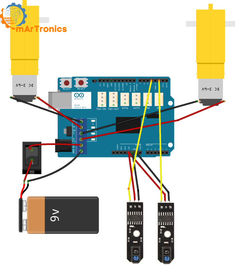
Motor Connections (via Motor Shield)
| Motor | Motor Shield Terminal | Arduino Pin (via Shield) | Function |
|---|---|---|---|
| Left DC Motor | Channel A output | DIR_L = pin 12, PWM_L = pin 3 | Direction and speed of the left motor |
| Right DC Motor | Channel B output | DIR_R = pin 13, PWM_R = pin 11 | Direction and speed of the right motor |
KY-033 Sensor Connections
| KY-033 Sensor | Sensor Pin | Arduino Pin | Function |
|---|---|---|---|
| Left Sensor | S (Signal) | Digital pin 2 | Reads left line detection (HIGH/LOW) |
| Left Sensor | VCC | 5V | Power supply |
| Left Sensor | GND | GND | Ground |
| Right Sensor | S (Signal) | Digital pin 4 | Reads right line detection (HIGH/LOW) |
| Right Sensor | VCC | 5V | Power supply |
| Right Sensor | GND | GND | Ground |
Power and Battery Connections
| Connection | From | To | Notes |
|---|---|---|---|
| Battery positive | Battery + | Motor Shield VIN (or Arduino barrel jack) | Supplies power to Arduino and motors |
| Battery negative | Battery − | Motor Shield GND | Common ground |
| Power switch (optional) | Inline on battery + wire | — | Toggle switch for easy on/off |
Power tip: A 7.4V LiPo battery works best because it provides stable voltage for both the Arduino and the motors. A 9V alkaline battery will work for short tests, but it drains quickly under motor load and may cause inconsistent behavior. Also double-check polarity before connecting the battery.
Step 5: Understanding KY-033 Line Detection
Before writing any code, however, let us look at how the KY-033 sensor Arduino setup detects the line.
Basically, each KY-033 module has an infrared emitter and a receiver. The IR light bounces off the surface below the sensor. A light-colored (white) surface reflects strongly, while a dark surface absorbs most of the light. Then the onboard comparator circuit converts this into a digital output:
- HIGH (1): The sensor is over a reflective (white/light) surface. In this project, that means the sensor is on the line.
- LOW (0): The sensor is over a non-reflective (dark) surface. That means the sensor is off the line.
Important: This project uses a white line on a dark background. The code logic and sensor interpretation throughout this tutorial follow this setup. However, if you want to follow a dark line on a light background instead, you would need to invert the logic in the code (swap the HIGH and LOW conditions).
Each KY-033 module also has a small potentiometer for adjusting the detection sensitivity. In particular, this is useful when fine-tuning the sensor so it reliably distinguishes between the line and the background at your robot’s operating height.
Step 6: Programming the Line-Following Robot
GitHub Repository: Full Code and Files
Below is the complete Arduino sketch for this KY-033 line following robot, followed by a detailed explanation of each section. If you are new to Arduino code, review the Arduino programming basics tutorial first.
Complete Arduino Sketch
/**
 * Author: Omar Draidrya
 * Date: 2024/12/06
 * Line-Following Robot with KY-033.
 */
// Motor control pins
#define DIR_L 12  // Left motor direction
#define DIR_R 13  // Right motor direction
#define PWM_L 3   // Left motor speed (PWM)
#define PWM_R 11  // Right motor speed (PWM)
// Sensor pins
int sensorLeft = 2;    // Left sensor
int sensorRight = 4;   // Right sensor
void setup() {
  // Configure motor pins as outputs
  pinMode(DIR_L, OUTPUT);
  pinMode(DIR_R, OUTPUT);
  pinMode(PWM_L, OUTPUT);
  pinMode(PWM_R, OUTPUT);
  // Configure sensor pins as inputs
  pinMode(sensorLeft, INPUT);
  pinMode(sensorRight, INPUT);
  // Serial communication for debugging
  Serial.begin(9600);
}
void loop() {
  // Read sensor values
  int left = digitalRead(sensorLeft);
  int right = digitalRead(sensorRight);
  // Output sensor data (debugging)
  Serial.print("Sensor Left: ");
  Serial.print(left);
  Serial.print("  |  Sensor Right: ");
  Serial.println(right);
  // Control logic
  if (left == 1 && right == 1) {
    // Drive straight
    controlMotors(HIGH, HIGH, 105, 105);
  } else if (left == 1 && right == 0) {
    // Turn left
    controlMotors(HIGH, LOW, 105, 85);
  } else if (left == 0 && right == 1) {
    // Turn right
    controlMotors(LOW, HIGH, 85, 105);
  } else {
    // Line lost – stop motors
    // Rotate in place to find the line
    controlMotors(HIGH, LOW, 70, 70);  // Left motor forward, right motor backward
    // delay(500);  // Brief rotation
    // controlMotors(LOW, LOW, 0, 0);
  }
}
// Function to control motors
void controlMotors(int directionL, int directionR, int speedL, int speedR) {
  digitalWrite(DIR_L, directionL);
  digitalWrite(DIR_R, directionR);
  analogWrite(PWM_L, speedL);
  analogWrite(PWM_R, speedR);
}
Below is a detailed breakdown of the code so you can understand how each part of the KY-033 sensor-based line-following robot works.
6.1 Motor Pin Setup
#define DIR_L 12  // Left motor direction
#define DIR_R 13  // Right motor direction
#define PWM_L 3   // Left motor speed (PWM)
#define PWM_R 11  // Right motor speed (PWM)
These four pins control the two motors through the Motor Shield. DIR_L and DIR_R set the rotation direction of the left and right motors respectively (HIGH = forward, LOW = backward on this shield). PWM_L and PWM_R control the speed of each motor using pulse width modulation, where values range from 0 (stopped) to 255 (full speed).
6.2 Sensor Pin Setup
int sensorLeft = 2;  // Left sensor
int sensorRight = 4; // Right sensor
The two KY-033 sensors connect to digital pins 2 and 4. In other words, each sensor outputs HIGH (1) when it detects the white line and LOW (0) when it detects the dark background.
6.3 The setup() Function
void setup() {
  pinMode(DIR_L, OUTPUT);
  pinMode(DIR_R, OUTPUT);
  pinMode(PWM_L, OUTPUT);
  pinMode(PWM_R, OUTPUT);
  pinMode(sensorLeft, INPUT);
  pinMode(sensorRight, INPUT);
  Serial.begin(9600);
}
The setup function runs once when the Arduino starts. It then configures all four motor control pins as outputs and both sensor pins as inputs. In addition, it initializes serial communication at 9600 baud so that you can view sensor readings in the Arduino Serial Monitor for debugging.
6.4 Serial Debugging Output
Serial.print("Sensor Left: ");
Serial.print(left);
Serial.print(" | Sensor Right: ");
Serial.println(right);
The code prints the sensor readings to the serial monitor on every loop cycle. This is really helpful during testing. So, open the Arduino Serial Monitor (Tools > Serial Monitor) to watch the live values. As a result, you should see alternating 0 and 1 values as you move the sensors over the line and background. If both sensors always show the same value, then check your wiring and sensor height.
6.5 Main Loop Sensor Reading
int left = digitalRead(sensorLeft);
int right = digitalRead(sensorRight);
At the start of each loop cycle, the Arduino reads the current digital state of both KY-033 sensors. The variable left holds the reading from the left sensor (pin 2) and right holds the reading from the right sensor (pin 4). In other words, these values are either 1 (on the line) or 0 (off the line).
6.6 Decision Logic
if (left == 1 && right == 1) {
  controlMotors(HIGH, HIGH, 105, 105);
} else if (left == 1 && right == 0) {
  controlMotors(HIGH, LOW, 105, 85);
} else if (left == 0 && right == 1) {
  controlMotors(LOW, HIGH, 85, 105);
} else {
  controlMotors(HIGH, LOW, 70, 70);
}
This is the core steering logic. Based on the four possible combinations of two sensor readings, the robot decides what to do:
- Both sensors HIGH (1, 1), drive straight: Because both sensors are on the line, both motors run forward at the same speed (105), so the robot drives straight ahead.
- Left HIGH, right LOW (1, 0), turn left: The left sensor is still on the line but the right sensor has moved off, so the robot has drifted to the right. So the left motor runs forward (105) while the right motor runs backward at lower speed (85), which steers the robot back to the left.
- Left LOW, right HIGH (0, 1), turn right: This is the opposite case: the right sensor is on the line but the left has drifted off. Similarly, the right motor runs forward (105) while the left runs backward (85), so it corrects to the right.
- Both sensors LOW (0, 0), line lost, search: Because neither sensor detects the line, the robot rotates in place (left motor forward, right motor backward at speed 70) to scan for the line. As soon as a sensor picks up the line again, normal steering resumes.
6.7 The controlMotors() Function
void controlMotors(int directionL, int directionR, int speedL, int speedR) {
  digitalWrite(DIR_L, directionL);
  digitalWrite(DIR_R, directionR);
  analogWrite(PWM_L, speedL);
  analogWrite(PWM_R, speedR);
}
This helper function simplifies motor control throughout the code. It takes four parameters: the direction (HIGH or LOW) and speed (0–255) for each motor. It writes the direction to the DIR_L and DIR_R pins and the speed to the PWM_L and PWM_R pins. Because every movement command in the decision logic calls this single function, the code stays clean and easy to modify.
Step 7: How to Test and Tune the Robot
At this point, with everything assembled, wired, and programmed, it is time to test your KY-033 line following robot. A 50mm wide white adhesive tape on a dark surface (like a dark tabletop or dark poster board) works well as a test track.
7.1 Prepare the Test Track
Start with a simple straight line of white tape, about 1 to 2 meters long. Once the robot follows a straight line reliably, then add gentle curves. Avoid sharp 90-degree turns at first. Although this approach handles smooth curves, it can struggle with very tight angles.
7.2 Sensor Position and Height
Ideally, the KY-033 sensors should be mounted 5 to 15 mm above the ground and spaced slightly wider than the line width. For instance, if the sensors are too high, they may not distinguish the line from the background. Likewise, if they are too close together, then the robot may not turn quickly enough on curves.
7.3 First Test: Serial Monitor Check
Before running the robot on the track, connect it to your computer via USB. Then open the Arduino Serial Monitor and manually move the robot over the line. Then verify that each sensor shows HIGH (1) when over the white tape and LOW (0) when over the dark surface. However, if you see reversed or inconsistent readings, adjust the KY-033 onboard potentiometer or check your wiring.
7.4 First Run on the Track
Next, place the robot on the track with both sensors centered over the white line. Then power it on and watch what happens. If everything is working, the robot should then drive forward along the line, gently correcting left and right as the sensors detect the edges.
7.5 Tuning Motor Speeds
For example, if the robot moves too fast and overshoots turns, reduce the speed values in the code (the 105 and 85 values in the controlMotors calls). On the other hand, if it moves too slowly and stalls, increase them. In general, small changes of 5 to 10 units at a time work best. Also, the straight-line speed and turning speed can be tuned independently.
7.6 Tuning the Search Behavior
Whenever both sensors lose the line, the robot rotates in place at speed 70. If it rotates too aggressively and overshoots the line, lower this value. On the other hand, if it rotates too slowly and cannot find the line, increase it. Additionally, you can uncomment the delay and stop lines in the code to add a brief pause after rotating, which helps on some tracks.
7.7 Improving Turning Smoothness
To further improve handling, try reducing the speed difference between the two motors during correction (for example, use 100 and 90 instead of 105 and 85). Smaller differences produce gentler turns, which work well on wide curves, while larger differences produce sharper corrections, which are better for tighter tracks.
Troubleshooting
If your line following robot is not behaving as expected, check the following common issues below.
Sensor and Detection Issues
| Problem | Possible Cause | Solution |
|---|---|---|
| Robot spins in place continuously | Both sensors always read LOW (the line is not being detected) | Check sensor height (should be 5–15 mm above ground). Adjust the KY-033 potentiometer. Verify the line is white/light-colored on a dark background. |
| Robot does not detect the line at all | Sensor wiring is incorrect or sensor is faulty | Verify signal wires are connected to pins 2 and 4. Check VCC and GND connections. Test each sensor individually using Serial Monitor. |
| Both sensors always give the same reading | Sensors are too close together or too high above the ground | Space the sensors slightly wider than the line width. Lower the sensor holder closer to the ground. |
| Robot follows poorly on curves | Motor speed difference during turns is too small or too large | Adjust the speed values in the turning conditions. Try different combinations of forward and reverse speeds. |
| Motors are too fast or too slow | PWM speed values are not tuned for your motors and battery voltage | Increase or decrease the speed values (105, 85, 70) in small increments of 5–10. |
Motor and Power Issues
| Problem | Possible Cause | Solution |
|---|---|---|
| Unstable behavior or erratic movements | Sensor height is inconsistent or surface is uneven | Ensure sensors are level and at a consistent height. Use a flat surface for testing. Check for loose wires. |
| Robot does not move at all | Battery is dead, power connections are wrong, or Motor Shield is not seated properly | Check battery voltage. Verify Motor Shield is fully seated on the Arduino. Check motor terminal connections. |
| One motor runs but the other does not | Wiring issue on one motor channel | Check the motor terminal connections on the Motor Shield. Swap motors to determine if the issue is the motor or the shield channel. |
| Robot moves backward instead of forward | Motor wires are reversed | Swap the two wires on the affected motor terminal, or change the direction value (HIGH/LOW) in the code. |
Still Having Issues?
However, if none of the solutions above work, open the Arduino Serial Monitor and check the raw sensor values while you manually move the robot over the line. This usually reveals wiring mistakes or sensitivity issues that would otherwise be hard to spot. You can also visit the GitHub repository for the latest code updates and additional notes.
Frequently Asked Questions (FAQ)
The KY-033 is a digital infrared line-tracking sensor module. It has an IR LED that emits infrared light and a photodiode that detects reflected light. When placed above a light-colored surface, the IR light reflects back and the sensor outputs HIGH (1). A dark surface absorbs the light, so the sensor outputs LOW (0). An onboard potentiometer allows you to adjust the detection sensitivity.
Yes, the KY-033 works on both setups. The code in this tutorial targets a white line on a dark background (HIGH = on line). To follow a black line on a white background, you need to invert the logic in the code: swap the conditions so that LOW means “on the line” and HIGH means “off the line.”
This project uses an Arduino Uno, which is the most common Arduino board for beginners. Any Uno-compatible board will work. If you are new to Arduino, see the What is Arduino? overview on OmArTronics.
Yes, you can use other motor drivers like the L298N module or the Adafruit Motor Shield. You will need to update the pin definitions and possibly the motor control logic in the code to match the new driver.
A line width of about 30 to 50 mm works well with this two-sensor setup. The line should be wide enough that both sensors can sit on it during straight segments but narrow enough that only one sensor moves off the line during turns. A 50 mm wide white adhesive tape is a good starting point.
Mount the sensors about 5 to 15 mm above the surface. If mounted too high, the sensor cannot distinguish the line from the background. Too low and the sensor may scrape the surface or give inconsistent readings. Test by manually checking the Serial Monitor output at different heights.
This usually means both sensors are reading LOW (no line detected) all the time. To fix this, check that the sensors are at the correct height, you have adjusted the potentiometer sensitivity, and the line is a light color on a dark background. Also verify the sensor wiring is correct.
A 7.4V LiPo battery (2S) is recommended for consistent power. A 9V alkaline battery works for short tests but drains quickly. Avoid batteries below 7V as the Arduino voltage regulator needs at least 7V input through the barrel jack or VIN pin for stable operation.
The 3D-printed chassis and holders make the build clean and repeatable, but you do not need a 3D printer. You can use a simple acrylic, cardboard, or wooden platform as the chassis and mount the components with screws, hot glue, or cable ties. The electronics and code stay the same.
The biggest improvements come from tuning the motor speeds, adjusting the sensor spacing, and keeping the sensor height consistent. For much smoother and more accurate line following, upgrade to the TCS34725 RGB sensor with PID control, which is covered in the next tutorial in this series.
PID (Proportional-Integral-Derivative) control is an algorithm that calculates smooth correction values instead of simple on/off decisions. It produces much smoother line following, especially on complex tracks with tight curves. This beginner tutorial uses simple threshold logic to keep the code easy to understand. The advanced follow-up tutorial on OmArTronics adds PID control for a big upgrade in performance.
Yes. For example, adding more KY-033 sensors (3 or 5 sensors in a row) gives the Arduino more information about the robot’s position relative to the line, which allows for more precise proportional steering. It is a common upgrade and a good intermediate project after completing this build.
Resources and Downloads
- GitHub repository: Full Arduino code for this project
- STL files for 3D printing: Download from Cults3D | OmArTronics Shop
- YouTube video walkthrough: Watch the build and testing video
Recommended Next Projects
Now that you have built your first line following robot, here are some OmArTronics tutorials to keep going:
- Line Following Robot with TCS34725 RGB Sensor and PID Control, the direct upgrade to this project with smoother, more accurate tracking
- Bluetooth-Controlled Robot Car with Arduino and HC-05, where you build a phone-controlled mobile robot
- Obstacle-Avoiding Robot Car with Arduino and Ultrasonic Sensor, which adds autonomous obstacle avoidance
- OmObiArm: Mobile Robot with Integrated Robotic Arm, a more advanced mobile robot project with a robotic arm
- Arduino Servo Control Guide, covering servo motor fundamentals for robotics
- L298N Motor Driver with Arduino, covering DC motor control in depth
Conclusion
You now have a working KY-033 line following robot with Arduino, built from scratch. Along the way, you learned how infrared sensors detect line contrast, how an Arduino and motor shield drive two DC motors with differential steering, and how simple threshold logic can make a robot follow a path on its own. On top of that, you also got hands-on experience with 3D design, mechanical assembly, wiring, and Arduino programming, all of which will also carry over to more advanced robotics work.
This beginner approach works well for gentle curves and simple tracks. When you are ready for sharper turns, therefore, complex paths, and smoother behavior, continue with the TCS34725 RGB sensor and PID control tutorial, which builds directly on this project. So, happy building!
Download the 3D Print Files (STL)
All 3D-printable STL files for this project are available for download. You can get them from our shop or browse them on Cults3D:
- OmArTronics Shop: Download project files from OmArTronics. Get the complete project package with STL files, wiring diagrams, and source code delivered to your email.
- Cults3D: View on Cults3D. Browse and download the 3D model files on Cults3D.
1 thought on “Building a Line Following Robot with KY-033 Sensors for Beginners”