
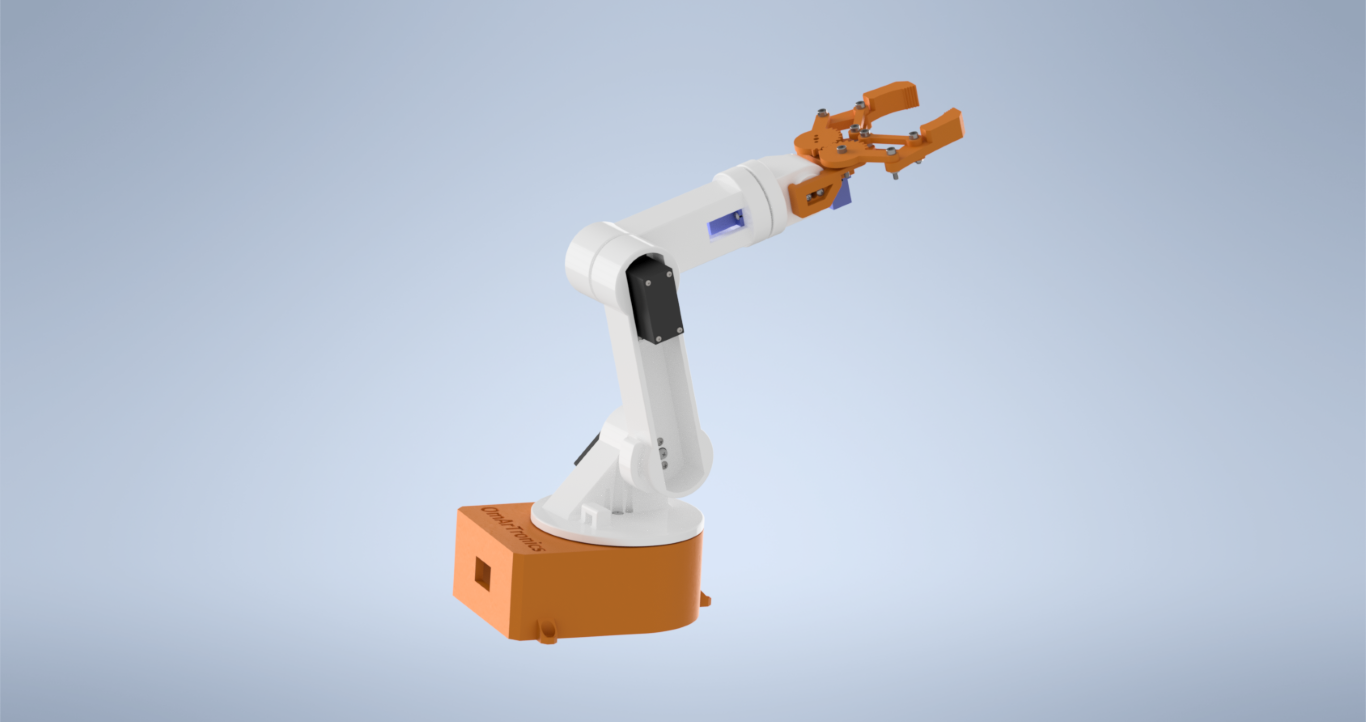
في هذا الدرس التعليمي، ستتعلم خطوة بخطوة كيفية بناء ذراع روبوتية بست درجات حرية يمكنك صنعها بنفسك تم تصميم المشروع بالكامل من الصفر. وعلى وجه التحديد، يغطي المشروع كل مرحلة من مراحل البناء - بدءًا من تصميم كل جزء في برنامج Autodesk Inventor وطباعته ثلاثي الأبعاد، وصولاً إلى توصيل الإلكترونيات باستخدام Arduino وبرمجة التحكم في المحركات المؤازرة في الوقت الحقيقي باستخدام مقاييس الجهد.
يستخدم هذا الذراع الروبوتي ذو الست درجات حرية الذي يمكنك صنعه بنفسك ثلاثة محركات سيرفو عالية العزم MG996R بالنسبة لمفاصل القاعدة والكتف والمرفق التي تتحمل الرفع الثقيل، وثلاثة محركات سيرفو صغيرة SG90 للمعصم الخفيف والقبضة المحكمة. على سبيل المثال، للاطلاع على شرح مبسط لكيفية عمل هذه المحركات، راجع قسمنا دليل التحكم في محرك المؤازرة. وبدورها، يتم التحكم في كل محرك مؤازر في الوقت الفعلي بواسطة مقياس جهد مخصص بقيمة 10 كيلو أوم، ويتم التعامل مع جميع إشارات تعديل عرض النبضة الست بواسطة لوحة تشغيل محرك سيرفو PCA9685 عبر بروتوكول I²C - مما يحافظ على نظافة الأسلاك ويحرر منافذ Arduino للترقيات المستقبلية.
سواء كنت هاويًا تبني روبوتك الأول أو طالب هندسة تبحث عن مشروع عملي في مجال الميكاترونيك، يرشدك هذا الدليل خطوة بخطوة عبر كل التفاصيل، مع قائمة كاملة بالمواد، وإعدادات الطباعة، ومخططات الأسلاك، وشفرة المصدر. عندما تكون جاهزًا، يمكنك مشاهدة فيديو البناء الكامل أدناه أو متابعة قراءة الدليل المكتوب.
نظرة عامة على المشروع
بشكل عام، يتم تنظيم عملية البناء في أربع مراحل رئيسية: التصميم بمساعدة الحاسوب (CAD), الطباعة ثلاثية الأبعاد, التجميع الميكانيكي, ، و توصيلات إلكترونية مع برمجة. علاوة على ذلك، يتم تصميم كل ملف STL قابل للطباعة ثلاثية الأبعاد في برنامج Autodesk Inventor بتفاوتات دقيقة لحوامل المؤازرة ومقاعد المحامل، بحيث تتناسب الأجزاء معًا دون تعديل.
على صعيد الإلكترونيات، يقوم أردوينو أونو بقراءة القيم التناظرية من ستة مقاومات متغيرة بقيمة 10 كيلو أوم، ويرسل أوامر I²C إلى مُشغّل PWM ذي 16 قناة من نوع PCA9685. بدوره، يُخرج المُشغّل عرض النبضات المناسب لكل محرك سيرفو. ونتيجةً لذلك، يحافظ هذا التصميم على تيار السيرفو العالي منفصلاً تماماً عن الأردوينو، مما يتيح إضافة مستشعرات أو وحدات لاسلكية لاحقاً.
قائمة المواد الكاملة
قبل البدء، اجمع جميع المكونات المذكورة في الجدول أدناه. سيضمن وجود جميع الأجزاء في متناول يدك تجنب التوقفات المحبطة أثناء عملية البناء.
أجزاء ومكونات ذراع روبوتية بست درجات حرية
| غرض | كمية | جزء | وصف |
|---|---|---|---|
| 1 | 1 | الأساس_1 | باختصار، المنصة الأساسية |
| 2 | 1 | base_link_upper1 | وبالمثل، القسم السفلي العلوي |
| 3 | 1 | arm_link_1 | وبالتحديد، وصلة الذراع الأولى |
| 4 | 1 | arm_link_2 | وبالمثل، وصلة الذراع الثانية |
| 5 | 1 | arm_link_3 | وبالمثل، وصلة الذراع الثالثة |
| 6 | 1 | قاعدة المقبض | باختصار، قاعدة ماسكة |
| 7 | 1 | Gripper_2 | وبالمثل، إصبع القابض |
| 8 | 1 | جير_رايت | معدات التثبيت (يمين) |
| 9 | 1 | الترس الأيسر | معدات التثبيت (يسار) |
| 10 | 1 | ماسك | مجموعة الماسك |
| 11 | 4 | وصلة | أجزاء وصلة الماسك |
| 12 | 2 | فاصل | فواصل مفصل الماسك |
| 13 | 3 | محرك سيرفو MG996R | باختصار، محرك سيرفو عالي العزم (القاعدة، الكتف، الكوع) |
| 14 | 3 | محرك سيرفو صغير SG90 | وبالمثل، محرك سيرفو صغير (معصم، ماسك) |
| 15 | 14 | ANSI B18.6.4 رقم 2-32 3/8 بوصة | وبالتحديد، برغي رأس العارضة، رقم 2-32 |
| 16 | 2 | ANSI B18.6.4 رقم 2-32 1/4 بوصة | مسمار رأس دعامة، رقم 2-32 |
| 17 | 3 | DIN 7985 M1.6×2-Z | برغي متقاطع M1.6×2 |
| 18 | 7 | ISO 4762 M3x16 (AS 1420) | باختصار، برغي ذو رأس سداسي M3×16 |
| 19 | 12 | ISO 4032 M3 (AS 1112) | وبالمثل، صامولة سداسية M3 |
| 20 | 2 | ANSI B18.6.4 رقم 2-32 1/2 بوصة | مسمار رأس دعامة، رقم 2-32 |
| 21 | 3 | بوق MG955 | بوق لبندقية MG996R |
| 22 | 3 | DIN 7985 M3x6-Z | برغي متقاطع M3×6 |
| 23 | 3 | ذراع سيرفو SG90 | بوق لـ SG90 |
| 24 | 2 | ANSI B18.6.4 رقم 2-32 3/8 بوصة | مسمار رأس دعامة، رقم 2-32 |
| 25 | 12 | ANSI B18.6.4 رقم 3-28 1/2 بوصة | مسمار رأس دعامة، رقم 3-28 |
| 26 | 1 | محمل كروي 6806ZZ (30x42x7) | على وجه التحديد، محمل ذو أخدود عميق (30×42×7) |
| 27 | 1 | أردوينو أونو أو ميجا | باختصار، وحدة التحكم الرئيسية |
| 28 | 1 | لوحة تشغيل المؤازرة PCA9685 | وبالتحديد، مشغل PWM ذو 16 قناة (I²C) |
| 29 | 6 | مقياس جهد 10 كيلو أوم | وبالمثل، مقبض تحكم تناظري لكل محرك سيرفو |
| 30 | 1 | لوح التجارب | باختصار، قاعدة توصيل لمقاييس الجهد |
| 31 | 1 | مزود طاقة 5 فولت 10 أمبير | والأهم من ذلك، مصدر طاقة المؤازرة |
| 32 | 1 | أسلاك توصيل (ذكر-ذكر) | على وجه التحديد، وصلات أردوينو ↔ PCA9685 |
| 33 | 1 | أسلاك توصيل (ذكر-أنثى) | وبالمثل، توصيلات مقياس الجهد الكهربائي مع أردوينو |
| 34 | 1 | لوح خشبي | بشكل أساسي، منصة تثبيت الذراع |
تصميم الأجزاء في برنامج Autodesk Inventor
المرحلة الأولى هي تصميم كل مكون في برنامج Autodesk Inventor. يتيح لك هذا البرنامج، المصمم بتقنية CAD البارامترية، تحديد الأبعاد بدقة، وتنعيم الحواف لزيادة المتانة، والتحقق من التوافق قبل طباعة أي غرام من خيوط الطباعة ثلاثية الأبعاد. إذا كنت جديدًا على برنامج Inventor أو الطباعة ثلاثية الأبعاد، فراجع دليلنا. مقدمة في الطباعة ثلاثية الأبعاد والتصميم ثلاثي الأبعاد باستخدام برنامج Inventor قبل البدء.
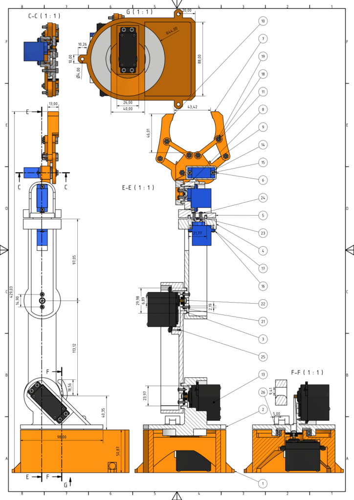
بشكل أساسي، هناك نوعان من المحركات المؤازرة يحددان قيود التصميم. محركات سيرفو صغيرة SG90 تتميز هذه الأجزاء بخفة وزنها، مما يسمح لها بالتعامل مع المفاصل العلوية والمقبض بفضل حجمها الصغير، بينما محركات سيرفو MG996R تُزوّد هذه الآلية قاعدة الدوران ومفصلي الكتف والمرفق الثقيلين بالطاقة اللازمة لتحريك الذراع بالكامل. يوضح الرسم الفني أدناه جميع أبعاد الأجزاء، والمقاطع العرضية، وعلاقات التجميع - استخدمه كمرجع عند التحقق من دقة الطباعة.
طباعة مكونات الذراع الروبوتية ذات الست درجات حرية بتقنية الطباعة ثلاثية الأبعاد
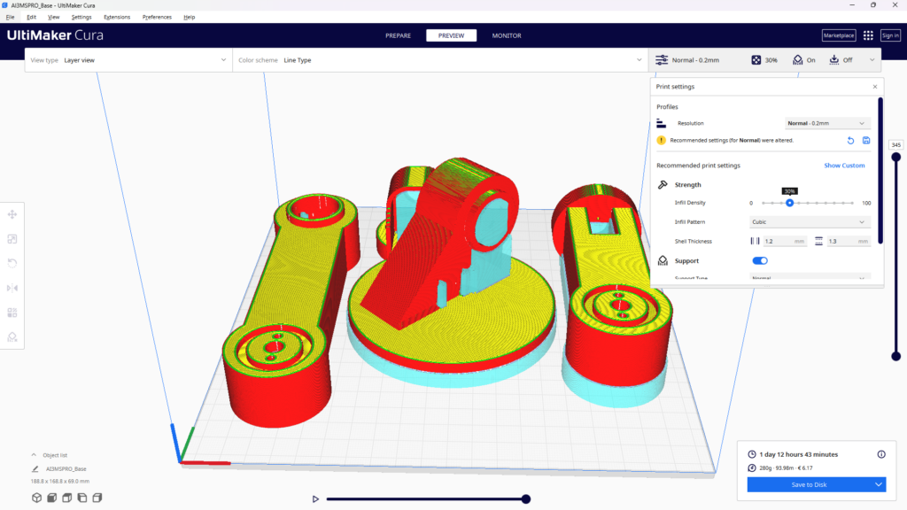
بعد تصدير ملفات STL من برنامج Inventor، حان وقت تشغيل الطابعة ثلاثية الأبعاد. بالنسبة لهذا المشروع،, خيوط PLA يُنصح باستخدامه لسهولة طباعته وجودة إعادة إنتاج التفاصيل. وللحصول على أفضل النتائج، استخدم ارتفاع طبقة يبلغ 0.2 مم وعلى الأقل حشوة 40% للأجزاء الهيكلية مثل القاعدة ووصلات الذراع.
انتبه جيدًا لتجاويف تثبيت المحركات المؤازرة، إذ يجب أن تكون دقيقة الأبعاد لضمان تثبيت المحركات بإحكام. بعد الطباعة، قم بإجراء معالجة بسيطة: أزل مواد الدعم، وصنفر أسطح التلامس، واختبر تركيب كل محرك مؤازر قبل الانتقال إلى مرحلة التجميع.

تجميع ذراعك الروبوتية ذات الست درجات حرية بنفسك
بعد طباعة جميع الأجزاء وتجربتها، يمكنك البدء بالتجميع العملي. لذا، اتبع كل خطوة بالترتيب - يُبنى الذراع من القاعدة إلى الأعلى. بالإضافة إلى ذلك، اختبر كل مفصل للتأكد من دورانه بسلاسة قبل الانتقال إلى الخطوة التالية.

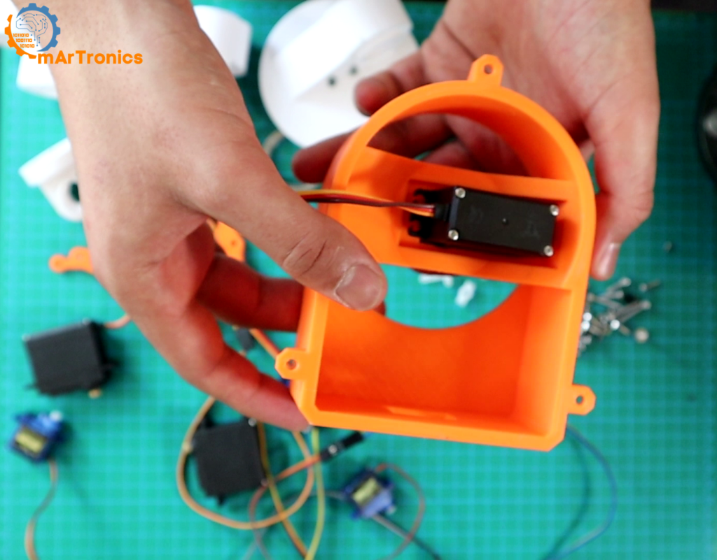
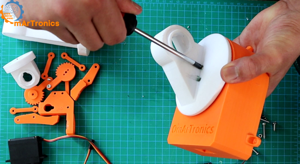
الخطوة 1: تجميع القاعدة
قبل كل شيء، القاعدة هي أساس الذراع بأكملها، لذا فإن الدقة هنا أمر بالغ الأهمية.
- تأمين محرك المؤازرة — قم بتركيب محرك MG996R الأول في قاعدة التثبيت باستخدام البراغي المرفقة (أو براغي ذاتية التثبيت برأس متقاطع M3×12). يوفر هذا المحرك الحركة الدورانية الأساسية للذراع.
- إضافة محمل الكرات (6806ZZ، 30×42×7 مم) — قم بتركيب محمل الكرات ذي الأخدود العميق في مكانه على القاعدة. وبالتحديد، يقع المحمل بين لوحة القاعدة الثابتة والمنصة العلوية الدوارة، مما يقلل الاحتكاك ويطيل عمر المفصل.
- توصيل ذراع المؤازرة — ثبّت ذراع المؤازرة على المنصة العلوية الدوارة باستخدام براغي ذاتية التثبيت M2×12. والأهم من ذلك، تأكد من إحكام التثبيت، حيث ينقل هذا الذراع كامل قوة الدوران من المؤازرة إلى باقي الذراع فوقه.

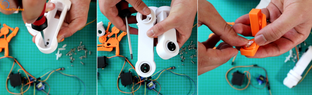
الخطوة الثانية: تركيب أذرع المؤازرة على وصلات الذراع
بعد ذلك، قم بمحاذاة كل ذراع من أذرع المؤازرة مع نقطة تثبيت وصلة الذراع المقابلة له، ثم ثبّته بمسمارين لكل ذراع. تأكد تحديدًا من محاذاة الثقوب بدقة تامة، لأن عدم محاذاة الذراع سيؤدي إلى احتكاك وحركة غير منتظمة، لذا تحقق جيدًا من كل وصلة قبل إحكام ربطها بالكامل.
الخطوة 3: تركيب محركات المؤازرة على وصلات الذراع
بعد ذلك، ضع كل محرك سيرفو في مكانه المخصص له والمطبوع بتقنية الطباعة ثلاثية الأبعاد على وصلة الذراع، مع التأكد من التوجيه الصحيح. ثم، اربط المحرك بمسمارين لكل محرك واختبر ثباته بالضغط عليه برفق - يجب ألا يتحرك محرك السيرفو أو يهتز على الإطلاق. في الواقع، يُعد تثبيت المحرك بشكل متين أمرًا ضروريًا لحركات الذراع الدقيقة والمتكررة.
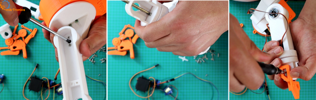
الخطوة الرابعة: توصيل وصلات الذراع
بعد ذلك، قم بتوصيل أجزاء الوصلات والمحركات المؤازرة معًا. أولًا، ضع ذراع التحكم على إحدى الوصلات بحيث ينزلق في نقطة تثبيت الوصلة التالية، ثم ثبّته بالبراغي. أخيرًا، اربط البراغي بالتساوي للحفاظ على تماسك الهيكل وسلاسة حركة المفاصل في جميع أنحاء الذراع.

الخطوة 5: تجميع الماسك
بعد ذلك، قم بتثبيت مجموعة الماسك الفرعية على وصلة نهاية الذراع. يستخدم الماسك محرك سيرفو صغير SG90 مزودًا بترسين مطبوعين بتقنية الطباعة ثلاثية الأبعاد لفتح وإغلاق الأصابع. استخدم براغي M3×20 لمفاصل الماسك وتأكد من أن الأصابع تتحرك بحرية تامة دون أي احتكاك.
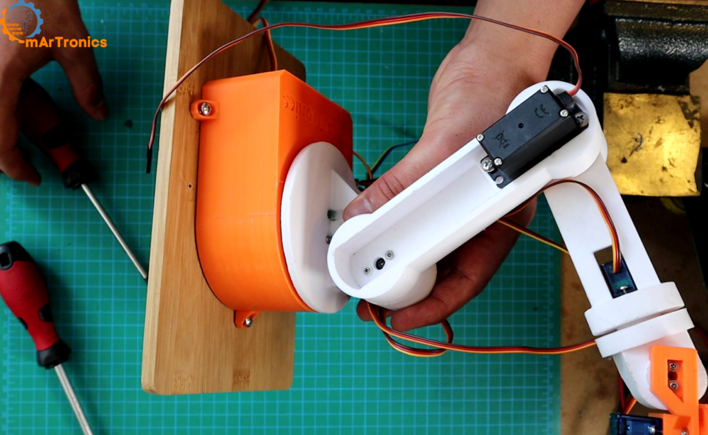
الخطوة السادسة: تثبيت الذراع على قاعدة خشبية
أخيرًا، قم بتثبيت الذراع المُجمّع بالكامل على لوح خشبي مسطح باستخدام براغي ذاتية الثقب M3×12. وبذلك، تمنع القاعدة الصلبة الذراع من الانقلاب أثناء الحركات السريعة، وتوفر منصة ملائمة لتركيب لوحة التجارب ومصدر الطاقة لاحقًا.

توصيل ذراع الروبوت ذي الست درجات حرية: أردوينو ومحرك المؤازرة
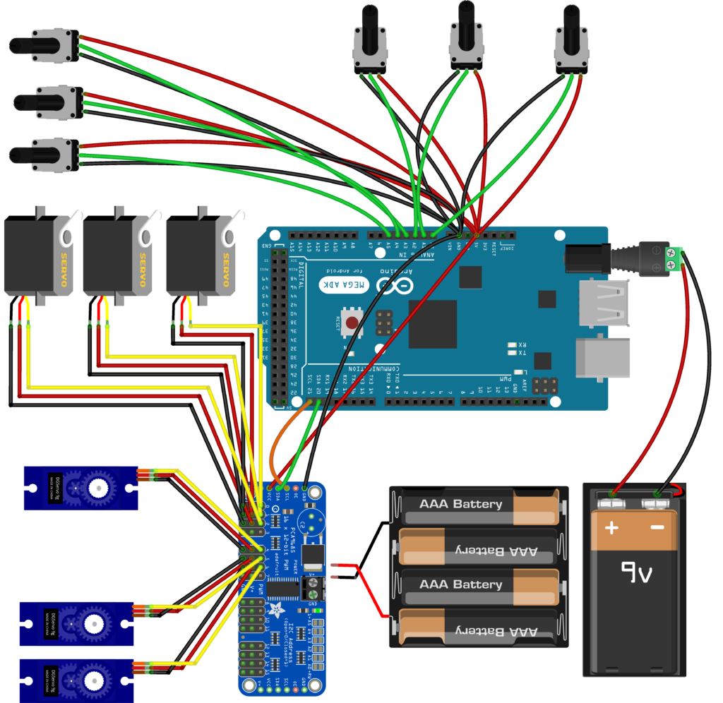
بمجرد الانتهاء من بناء الأجزاء الميكانيكية لذراع الروبوت ذي الست درجات حرية الذي تصنعه بنفسك، يحين وقت توصيل الإلكترونيات. يتكون نظام التحكم أساسًا من ثلاثة عناصر رئيسية: أردوينو أونو (أو ميجا) كوحدة تحكم دقيقة، لوحة تشغيل محرك سيرفو PCA9685 لتوليد إشارات تعديل عرض النبضة (PWM)، وستة مقاومات متغيرة 10 كيلو أوم لإدخال المستخدم.
دليل المكونات والأسلاك
- Arduino Uno / Mega — Essentially, the main controller. Essentially, it reads potentiometer values and sends I²C commands to the PCA9685.
- لوحة تشغيل المؤازرة PCA9685 — An I²C-controlled, 16-channel PWM driver. Furthermore, it handles all six servo signals, leaving room for expansion later.
- 5 V 10 A Power Supply — Importantly, provides dedicated power to the servos through the PCA9685 V+ terminal. Importantly, never power six servos from the Arduino’s 5 V pin — it cannot supply enough current.
- 6 × 10 kΩ Potentiometers — Correspondingly, connected to Arduino analog pins A0–A5. Essentially, turning a knob changes the voltage, which the Arduino reads as a value from 0 to 1023.
- Breadboard and Jumper Wires — Essentially, used to organize potentiometer connections cleanly.
Wiring Steps
- PCA9685 → Arduino: First, connect VCC to 5 V, GND to GND, SDA to A4, and SCL to A5. Similarly, on the Mega, SDA and SCL use pins 20 and 21 respectively.
- Servos → PCA9685: Next, plug each servo’s 3-pin connector into channels 0–5 on the PCA9685. Also, make sure the ground wire (brown or black) aligns with the bottom row of headers.
- Potentiometers → Arduino: Then, wire the outer legs of each pot to 5 V and GND on the breadboard, and connect the center (wiper) pin to A0 through A5.
- Servo Power Supply: Finally, connect the 5 V 10 A supply to the PCA9685 V+ and GND screw terminals. As a result, this keeps high servo current completely separate from the Arduino.
لماذا يحتاج الذراع الروبوتي ذو 6 درجات حرية إلى محرك سيرفو PCA9685
So, why not just drive servos straight from the Arduino? You can — however, it quickly becomes limiting. After all, the Arduino Uno has only six PWM-capable pins, and the built-in Servo library can conflict with other timer-dependent features like tone() or certain communication protocols.
Instead, the PCA9685 solves this by offloading all PWM generation to a dedicated chip. Specifically, it communicates over the I²C bus using just two wires (SDA and SCL) regardless of how many servos you control. Moreover, a single board handles 16 channels, and you can daisy-chain up to 62 boards for a theoretical maximum of 992 servos.
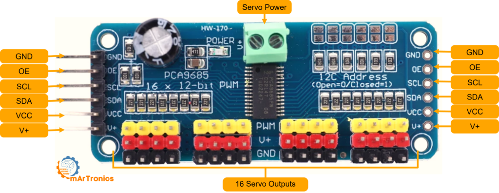
مرجع توصيلات PCA9685
- أرضي — Essentially, common ground shared with the Arduino.
- OE (Output Enable) — By default, active low. Therefore, leave unconnected to keep all outputs enabled by default.
- SCL — Specifically, I²C clock line for synchronization.
- السبتيين — Similarly, I²C data line for communication.
- VCC — Specifically, logic power at 3.3–5 V. Notably, powers only the PCA9685 chip, not the servos.
- V+ — Importantly, servo power rail (up to 6 V). Then, connect your external supply here via the polarized screw terminal.
Consequently, each channel on the board has a 3-pin header that accepts a standard servo connector directly, making wiring quick and error-proof.
برمجة الذراع الروبوتية ذات 6 درجات حرية للتحكم المؤازر
Ultimately, the Arduino sketch ties everything together. Essentially, it reads the voltage on each analog pin, converts it into a servo pulse width, and sends the result to the PCA9685. Below is how the key logic works, step by step.
How the Code Works
- Library Initialization — First, the sketch includes
Wire.hfor I²C andAdafruit_PWMServoDriver.hfor the PCA9685. Insetup(), it callspwm.begin()and sets the PWM frequency to 60 Hz — the standard refresh rate for hobby servos. - Reading the Potentiometers — Inside
حلقة(),Next, analogRead(A0)throughanalogRead(A5)returns a value between 0 and 1023, corresponding to the knob position. - Subsequently, mapping to Servo Pulse - ال
رسم خريطة()function converts the 0–1023 range into a 125–575 tick range. These tick values represent the minimum and maximum pulse widths the PCA9685 outputs at 60 Hz (roughly 1 ms to 2.3 ms), which correspond to the servo’s full rotation range. - Then, setting the PWM Output —
pwm.setPWM(channel, 0, ticks)In turn, sends the computed pulse to the correct PCA9685 channel. The second parameter (0) is the “on” tick, and the third is the “off” tick within the 4096-step PWM cycle. - Loop Delay — Finally, a 20 ms delay at the end of each loop keeps the refresh rate smooth and prevents flooding the I²C bus.
Finally, upload the following sketch to your Arduino Uno (or Mega). Make sure the مكتبة برامج تشغيل محركات سيرفو PWM من Adafruit is installed via the Arduino Library Manager before compiling.
Arduino Sketch: Full Source Code
/**
 * Author: Omar Draidrya
 * Date: 2024/05/05
 * Controls 6 servos via PCA9685 with potentiometer input.
 */
#include <Wire.h>
#include <Adafruit_PWMServoDriver.h>
Adafruit_PWMServoDriver pwm = Adafruit_PWMServoDriver(); // Default address 0x40
void setup() {
    Serial.begin(9600);           // First, init serial.
    pwm.begin();                  // Then, init PCA9685.
    pwm.setPWMFreq(60);           // Specifically, 60 Hz for servos.
}
void loop() {
    // Servo 0
    int potValue0 = analogRead(A0);           // First, read A0
    int servoPos0 = map(potValue0, 0, 1023, 125, 575); // Map to pulse range
    pwm.setPWM(0, 0, servoPos0);              // Set servo 0
    // Servo 1
    int potValue1 = analogRead(A1);           // Then, read A1
    int servoPos1 = map(potValue1, 0, 1023, 125, 575); // Map to pulse range
    pwm.setPWM(1, 0, servoPos1);              // Set servo 1
    // Servo 2
    int potValue2 = analogRead(A2);           // Similarly, read A2
    int servoPos2 = map(potValue2, 0, 1023, 125, 575); // Map to pulse range
    pwm.setPWM(2, 0, servoPos2);              // Set servo 2
    // Servo 3
    int potValue3 = analogRead(A3);           // Next, read A3
    int servoPos3 = map(potValue3, 0, 1023, 125, 575); // Map to pulse range
    pwm.setPWM(3, 0, servoPos3);              // Set servo 3
    // Servo 4
    int potValue4 = analogRead(A4);           // Likewise, read A4
    int servoPos4 = map(potValue4, 0, 1023, 125, 575); // Map to pulse range
    pwm.setPWM(4, 0, servoPos4);              // Set servo 4
    // Servo 5
    int potValue5 = analogRead(A5);           // Finally, read A5
    int servoPos5 = map(potValue5, 0, 1023, 125, 575); // Map to pulse range
    pwm.setPWM(5, 0, servoPos5);              // Set servo 5
    delay(20);   // Finally, loop delay
}
Required Libraries
Before compiling, first install the following libraries through the Arduino IDE Library Manager: مكتبة برامج تشغيل محركات سيرفو PWM من Adafruit و سلك (included by default). After that, then select your board (Arduino Uno or Mega), choose the correct COM port, and click Upload.
معايرة واختبار ذراعك الروبوتية ذات 6 درجات حرية
Once your DIY 6-DOF robotic arm is fully wired, power on the servo supply and slowly turn each potentiometer. As a result, you should see the corresponding joint move in real time. If a joint moves in the wrong direction, swap the outer wires on that potentiometer to reverse it.
Fine-tune the رسم خريطة() range values (125 and 575) for each servo individually. For example, some servos may need slightly different minimum and maximum tick values to avoid mechanical end-stop buzzing. Lastly, test the arm under load by picking up small objects with the gripper to confirm torque and stability.
ذراع روبوتية بست درجات حرية: الخلاصة والخطوات التالية
Congratulations — you now have, indeed, a fully functional DIY 6-DOF robotic arm built entirely from scratch. Indeed, this project covers every core discipline of mechatronics: CAD design, additive manufacturing, electronic wiring, and embedded programming.
From here, consequently, the possibilities are wide open. You could add inverse kinematics for automated positioning, integrate a Bluetooth module for wireless control (we did exactly that in our Bluetooth-controlled robotic arm upgrade), or train the arm to record and replay movement sequences. Regardless of which direction you take, this six-axis platform gives you a solid foundation for deeper exploration into robotics and automation.
قم بتنزيل ملفات الطباعة ثلاثية الأبعاد (STL)
جميع ملفات STL القابلة للطباعة ثلاثية الأبعاد لهذا المشروع متاحة للتنزيل. يمكنك الحصول عليها من متجرنا أو تصفحها على موقع Cults3D.
- متجر أومارترونيكس: قم بتنزيل ملف المشروع من OmArTronics — احصل على حزمة المشروع الكاملة بما في ذلك ملفات STL ومخططات الأسلاك وشفرة المصدر التي يتم تسليمها إلى بريدك الإلكتروني.
- Cults3D: شاهد على موقع Cults3D — تصفح وقم بتنزيل ملفات النماذج ثلاثية الأبعاد على موقع Cults3D.
can u tell how to connect potentiometer with bread board
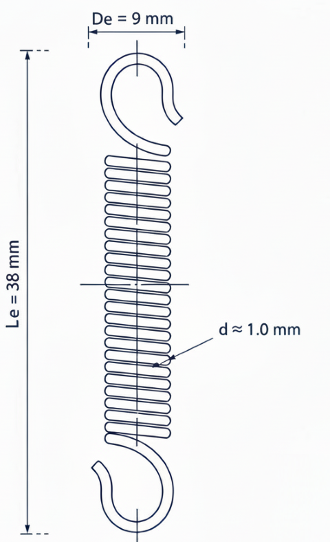
I am building an AI Robot and want to use your robotic arm in the build. I want to mount it on the front side vertically. I noticed on past photos there was a tension spring attached to the rotating base to the first arm piece but not listed in the parts list or build instructions. I wish to implement the spring back into the build because of its vertical placement on my robot. Can you provide me with the specifications for the spring? This robotic arm is in my opinion is one of the better designed and documented arms of its type out on the web.
Thanks a lot! I’m glad you liked the design
Yes, that tension spring connects the rotating base to the first arm segment to help support the shoulder joint, especially when the arm is mounted vertically.
The spring is about 2 cm long (at rest) and 9 mm in diameter.
I actually reused it from an old desk lamp stand, but you can find similar extension springs easily online or in hardware stores.
It’s optional but really helps balance the arm and reduce servo stress.
Hello! I wanted to ask the function of the atachment points on the base and the first link, are they for a spring? it is modelled but the pictures of the assembly don’t have this feature, nor is it referenced on the post. Thank you! this is a nice design
Yes, those points are for a spring. The spring is optional — it helps the shoulder joint carry part of the arm’s weight.
This feature was added in a later version of the design.
You can also use a rubber band, but I personally prefer a spring.
The one I used is about 2 cm long (at rest) and 9 mm in diameter.
I actually took it from an old desk lamp stand, but you can easily find similar springs online or in hardware stores.