
So, you want to build an obstacle avoiding robot car that drives itself and dodges walls on its own? This step-by-step tutorial walks you through the entire build, from chassis assembly to uploading the final Arduino sketch. You will use an Arduino Uno, an L293D motor shield, an SG90 servo motor, and an HC-SR04 ultrasonic sensor. As a result, the robot scans its surroundings with the ultrasonic sensor mounted on a servo, spots obstacles in its path, and steers around them automatically.
In addition, this obstacle avoiding robot car project is a practical way to learn motor control, servo positioning, sensor integration, and basic autonomous navigation. It also ties together concepts from earlier OmArTronics tutorials on Arduino programming basics, servo motor control, ultrasonic distance sensing, and DC motor control with motor drivers. By the end, you will have a working DIY obstacle avoidance robot you built from scratch.
📋 Quick Summary
Build an autonomous obstacle avoiding robot car using Arduino Uno, L293D motor shield, HC-SR04 ultrasonic sensor, and an SG90 servo motor for scanning. The robot detects obstacles, scans left and right to find the clearest path, and navigates on its own. Includes complete wiring, code, and troubleshooting.
What You Will Learn
- How the HC-SR04 ultrasonic sensor detects obstacles by measuring distance
- How a servo motor sweeps the ultrasonic sensor to scan the environment left and right
- How the L293D motor shield drives two DC motors for forward, reverse, and turning movement
- How the Arduino code decides when to stop, reverse, and choose a new direction
- How to assemble the complete robot chassis with battery power, wiring, and 3D-printed mounts
- How to upload, test, and tune the obstacle avoidance code
How the Obstacle Avoiding Robot Car Works
Before we start building, it helps to understand how all the parts work together. The obstacle avoiding robot car uses a sense-think-act loop to navigate around objects in its path.
Ultrasonic Sensor (HC-SR04) — The Robot’s Eyes
The HC-SR04 ultrasonic sensor first sends out a short ultrasonic pulse and then listens for the echo that bounces back from objects. The Arduino measures the time between sending and receiving, then calculates the distance to the nearest obstacle. This measurement happens many times per second while the robot drives.
Servo Motor (SG90) — The Scanner
The ultrasonic sensor is mounted on an SG90 servo motor. While driving forward, the servo sweeps the sensor left and right between 30° and 150°, so the robot gets a wide view of the path ahead. When an obstacle shows up nearby, the servo turns the sensor fully left (175°) and fully right (5°) to measure the distance on each side and figure out which way has more space.
L293D Motor Shield — The Muscle
The L293D motor shield sits on top of the Arduino and controls two DC motors. It handles direction (forward or reverse) and speed (via PWM) for each motor independently. If you run the left and right motors in opposite directions, the robot turns in place.
Decision Logic — The Brain
The Arduino runs a continuous loop: measure distance, decide, and act. If the path ahead is clear (more than 40 cm), the robot drives forward at a steady speed while scanning. As an obstacle gets closer (between 15 cm and 40 cm), the robot gradually slows down. When the distance drops below 15 cm, the robot stops, looks left and right, and turns toward whichever side has more open space. If both sides are blocked (a dead end), the robot reverses first, then scans again and picks a new direction.
Obstacle avoiding robot car components (bill of materials)
Here is everything you need to build this obstacle avoiding robot car. Most of these parts are common and inexpensive, so you can probably source them locally or online without much trouble.
Full parts list
| Component | Qty | Required / Optional | Purpose | Notes |
|---|---|---|---|---|
| Arduino Uno | 1 | Required | Main microcontroller — runs the obstacle avoidance code | Any Arduino Uno-compatible board works |
| L293D Motor Shield | 1 | Required | Drives and controls the two DC motors | Because it plugs directly on top of the Arduino Uno |
| DC Motors (3–6 V) | 2 | Required | Left and right drive wheels | Standard hobby geared DC motors |
| Servo Motor (SG90) | 1 | Required | Sweeps the ultrasonic sensor left and right to scan for obstacles | Any small 9g servo works |
| Ultrasonic Sensor (HC-SR04) | 1 | Required | Measures distance to obstacles using ultrasonic pulses | 4-pin module: VCC, Trig, Echo, GND |
| Jumper Wires | Several | Required | All electrical connections between components | M-M and M-F types |
| AA Rechargeable Batteries (1.5 V) | 8 | Required | Power supply for the motors and Arduino | 8 × 1.5 V = 12 V total. The motor shield accepts 5–12 V and powers the Arduino directly. |
| Battery Holders (4×AA) | 2 | Required | Hold and connect batteries in series | Wired in series to produce 12 V |
| Toggle Switch | 1 | Required | Main power on/off switch | Inline with the positive battery wire |
| Robot Chassis | 1 | Required | Frame to mount all components | Acrylic or 3D-printed platform |
| Wheels | 2 | Required | Attach to DC motors for movement | Match your motor shaft size |
| Support Wheel (Caster) | 1 | Required | Third point of contact for stability | Ball caster or swivel wheel |
| Screws, Nuts & Spacers | Assorted | Required | Mechanical assembly | M3 screws are common for Arduino and chassis |
| 3D-Printed Mounts | Set | Optional | Custom holders for servo motor, ultrasonic sensor, and Arduino | Can substitute with hot glue, zip ties, or brackets |
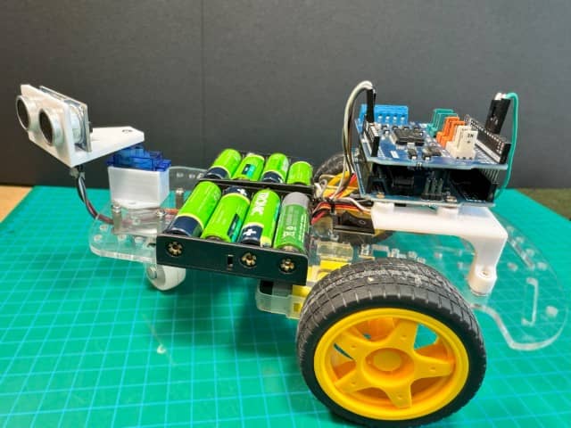
Step-by-step obstacle avoiding robot car assembly
Follow these steps to assemble the physical robot car before wiring and programming. Take your time with the mechanical build. A solid chassis makes everything else easier.
Step 1: Mount the Battery Holders
Secure both 4×AA battery holders to the underside or rear of the robot chassis using screws and nuts. Solder the output wires of the two holders in series (positive of one holder to negative of the other) so all 8 batteries connect in series for roughly 12 V total.
Step 2: Install the Power Switch
Solder a toggle switch inline with the positive wire coming from the battery series. Mount the switch somewhere easy to reach on the chassis so you can turn the robot on and off quickly.
Step 3: Attach the DC Motors
Solder wires to both terminals of each DC motor. Mount one motor on the left side and one on the right side of the chassis using screws, nuts, or motor brackets.
Step 4: Prepare the Arduino Mount
If you are using the 3D-printed Arduino mount, heat the threaded brass inserts with a soldering iron and press them into the mounting holes. This gives you strong, reusable screw threads for securing the Arduino.
Step 5: Mount the Arduino and Motor Shield
Secure the 3D-printed mount (or standoffs) onto the chassis. Next, place the Arduino Uno onto the mount and fasten it with screws. Then carefully plug the L293D motor shield onto the Arduino, while making sure all header pins are properly aligned.
Step 6: Install the Servo Motor
First, attach the 3D-printed servo motor mount to the front of the chassis using double-sided tape or screws. Then, insert the SG90 servo motor into the mount and secure it. The servo horn should be oriented so the ultrasonic sensor can rotate freely from left to right.
Step 7: Mount the Ultrasonic Sensor
Now, insert the HC-SR04 ultrasonic sensor into its 3D-printed bracket (or attach with hot glue). Secure the bracket onto the servo horn using a small screw so the sensor rotates with the servo.
Step 8: Attach the Support Wheel
For stability, mount the ball caster or swivel support wheel on the front or rear of the chassis (opposite the DC motors) because this gives the robot a stable three-point contact with the ground.
Step 9: Attach the Drive Wheels
Press the wheels onto the DC motor shafts on both sides. Make sure they are firmly attached and spin freely without rubbing on the chassis.
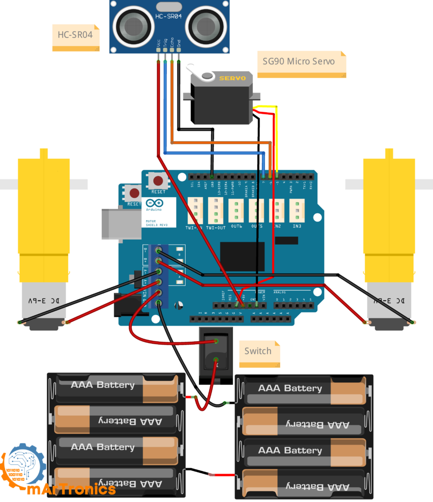
Wiring the obstacle avoiding robot car
With the mechanical assembly complete, it is time to connect all the electrical components. The wiring diagram below shows the full circuit. Refer to the wiring table for a quick connection reference.
DC Motor Connections
| Motor | Motor Shield Terminal |
|---|---|
| Left DC Motor wire 1 | A− |
| Left DC Motor wire 2 | A+ |
| Right DC Motor wire 1 | B− |
| Right DC Motor wire 2 | B+ |
Servo Motor Connections
| Servo Wire | Connects To |
|---|---|
| Signal (orange/yellow) | Arduino digital pin 5 (on the motor shield header) |
| VCC (red) | 5 V pin on the motor shield |
| GND (brown/black) | GND pin on the motor shield |
Important: Connect the servo’s power wire to the 5 V pin on the motor shield, not the 3.3 V pin. The SG90 servo requires 5 V to operate reliably. Using 3.3 V will cause jittering and weak movement.
Ultrasonic Sensor (HC-SR04) Connections
| HC-SR04 Pin | Connects To |
|---|---|
| VCC | 5 V on the motor shield |
| Trig | Arduino digital pin 7 |
| Echo | Arduino digital pin 6 |
| GND | GND on the motor shield |
Power Supply Connections
| Battery / Switch Wire | Connects To |
|---|---|
| Positive (from switch output) | Motor shield Vin / power terminal (+) |
| Negative (battery ground) | Motor shield GND / power terminal (−) |
The L293D motor shield regulates power for the Arduino through the Vin pin, so you do not need a separate USB cable once the batteries are connected. Just double-check all connections before inserting batteries, because reversed polarity can damage components.
Insert the Batteries
Place all 8 AA rechargeable batteries into the holders. Do not turn the switch on yet. We will upload the code first.
Arduino Code for the Obstacle Avoiding Robot Car
Here is the complete Arduino sketch for the obstacle avoiding robot car. Upload this code to your Arduino Uno using the Arduino IDE. Make sure the Servo library is installed (it comes pre-installed with the Arduino IDE).
Complete obstacle avoiding robot car Arduino sketch
/**
 * Author: Omar Draidrya
 * Date: 2024-06-18
 * This code controls a robot with ultrasonic sensors and servo motors to avoid obstacles.
 */
#include <Servo.h>
// Create a Servo object to control the servo motor
Servo myservo;
int pos = 0;  // Variable to store the servo position
// Define motor pins
int directionA = 12;  // Pin for direction of Motor A
int speedA = 3;  // Pin for speed of Motor A
int brakeA = 9;  // Pin for brake of Motor A
int directionB = 13;  // Pin for direction of Motor B
int speedB = 11;  // Pin for speed of Motor B
int brakeB = 8;  // Pin for brake of Motor B
// Define ultrasonic sensor pins
int trigger = 7;  // Trigger pin
int echo = 6;  // Echo pin
long duration = 0;  // Variable to store the duration of the echo
long distance = 0;  // Variable to store the distance from the obstacle
int currentAngle = 90;  // Start with the sensor facing forward
int scanDirection = 1;  // 1 for right, -1 for left
void setup() {
    // Attach the servo on pin 5 to the servo object
    myservo.attach(5);
    // Set the trigger pin as OUTPUT and the echo pin as INPUT
    pinMode(trigger, OUTPUT);
    pinMode(echo, INPUT);
    // Initialize Motor A pins
    pinMode(directionA, OUTPUT);
    pinMode(directionB, OUTPUT);
    pinMode(brakeA, OUTPUT);
    pinMode(brakeB, OUTPUT);
    // Apply brakes (stop the motors)
    digitalWrite(brakeA, HIGH);
    digitalWrite(brakeB, HIGH);
    // Set the servo to the center position initially
    myservo.write(90);
    delay(500);
}
Main loop and helper functions
void loop() {
    // Measure the distance to the nearest obstacle
    distance = measureDistance();
    if (distance < 40) {
        // Gradually reduce speed as the obstacle approaches
        int speed = map(distance, 20, 40, 75, 128);
        motorTurn(directionA, speedA, HIGH, speed);
        motorTurn(directionB, speedB, HIGH, speed);
        if (distance < 15) {
            // Stop the motors
            digitalWrite(brakeA, HIGH);
            digitalWrite(brakeB, HIGH);
            delay(500);
            // Check surroundings
            int leftDistance = checkDirection(175);
            int rightDistance = checkDirection(5);
            // Determine if the robot is in a dead end
            if (leftDistance < 15 && rightDistance < 15) {
                // Move backward
                motorTurn(directionA, speedA, LOW, 128);
                motorTurn(directionB, speedB, LOW, 128);
                delay(500);
                // Apply brakes
                digitalWrite(brakeA, HIGH);
                digitalWrite(brakeB, HIGH);
                delay(500);
                // Scan again after moving back
                leftDistance = checkDirection(30);
                rightDistance = checkDirection(150);
            }
            // Determine the best direction to turn
            if (leftDistance > rightDistance) {
                // Turn left
                motorTurn(directionA, speedA, LOW, 128);
                motorTurn(directionB, speedB, HIGH, 128);
            } else {
                // Turn right
                motorTurn(directionA, speedA, HIGH, 128);
                motorTurn(directionB, speedB, LOW, 128);
            }
            delay(500);
            // Apply brakes
            digitalWrite(brakeA, HIGH);
            digitalWrite(brakeB, HIGH);
            delay(500);
            // Set the servo back to the center position
            myservo.write(90);
            delay(500);
        }
    } else {
        // Move forward at a reduced speed
        motorTurn(directionA, speedA, HIGH, 100);
        motorTurn(directionB, speedB, HIGH, 100);
        // Continuously scan left and right
        currentAngle += scanDirection * 10;
        if (currentAngle >= 150 || currentAngle <= 30) {
            scanDirection = -scanDirection;
        }
        myservo.write(currentAngle);
        delay(40);  // Adjusted delay for more realistic servo movement
    }
}
Helper functions
// Function to set the direction and speed of motors
void motorTurn(int directionPin, int speedPin, int direction, int speed) {
    digitalWrite(directionPin, direction);
    analogWrite(speedPin, speed);
    if (directionPin == directionA) {
        digitalWrite(brakeA, LOW);
    } else {
        digitalWrite(brakeB, LOW);
    }
}
// Function to measure the distance using the ultrasonic sensor
int measureDistance() {
    digitalWrite(trigger, LOW);
    delayMicroseconds(2);
    digitalWrite(trigger, HIGH);
    delayMicroseconds(10);
    digitalWrite(trigger, LOW);
    duration = pulseIn(echo, HIGH);
    distance = (duration / 2) / 29.1;
    return distance;
}
// Function to check the distance in a specific direction
int checkDirection(int angle) {
    myservo.write(angle);
    delay(500);  // Give the servo time to move
    int measuredDistance = measureDistance();
    return measuredDistance;
}
Obstacle avoiding robot car code explanation
Here is a walkthrough of each section of the code, so you know what every part does and can tweak it later.
Pin Assignments
At the top of the sketch, we define which Arduino pins connect to each component. Motor A (left) uses pins 12 (direction), 3 (speed/PWM), and 9 (brake). Motor B (right) uses pins 13, 11, and 8. The ultrasonic sensor trigger is on pin 7, echo on pin 6, and the servo signal is on pin 5. These pin numbers are set by the L293D motor shield, so they are not arbitrary.
Distance Measurement
The measureDistance() function sends a 10-microsecond pulse on the trigger pin and then waits for the echo. It calculates the distance in centimeters using the formula: distance = (duration / 2) / 29.1. The division by 2 accounts for the round trip of the sound wave, and 29.1 is the approximate number of microseconds per centimeter for sound in air.
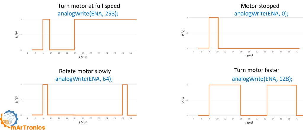
Motor Control
The motorTurn() helper function sets the direction and speed of a single motor. It writes the direction pin HIGH (forward) or LOW (reverse), sets the speed via analogWrite() (0-255), and releases the brake. Note that the motor shield uses separate brake pins, so setting the brake HIGH stops the motor right away.
How the obstacle avoiding robot car detects and slows down
Inside the main loop(), the robot measures the distance ahead on every cycle. If the distance is between 15 cm and 40 cm, the robot does not stop. Instead, it gradually reduces speed using the map() function. The closer the obstacle, the slower the robot moves. This creates smooth deceleration rather than an abrupt stop.
Obstacle avoiding robot car scan logic
When the distance drops below 15 cm, the robot stops both motors and then calls checkDirection(175) (look left) and checkDirection(5) (look right). The checkDirection() function rotates the servo to the given angle, waits for it to reach position, takes a distance reading, and returns it. The robot then compares the two distances and turns toward the side with more open space.
Dead-end reverse behavior
If both the left and right distances are below 15 cm, the robot is in a dead end. It reverses for 500 ms, stops, and then scans again at slightly different angles (30° and 150°) to re-evaluate. This gives the robot a chance to back out of tight corners and find a new way forward.
Servo sweep while the obstacle avoiding robot car drives
When the path ahead is clear (distance > 40 cm), the robot drives forward at a steady speed while the servo sweeps the ultrasonic sensor between 30° and 150° in 10° increments. This wide sweep lets the robot detect obstacles approaching from the sides, not just directly ahead. The scan direction reverses each time it reaches a boundary angle.
Upload, test, and observe the obstacle avoiding robot car
- Connect the Arduino to your computer via USB, and then open the Arduino IDE.
- Then, upload the sketch above to the Arduino Uno.
- Afterwards, disconnect USB, insert batteries, and then flip the power switch on.
- Observe the behavior: Specifically, the robot should drive forward, slow down as it approaches an obstacle, stop, scan left and right, and turn toward the clearer path.
- If the robot turns the wrong way, swap the two wires on one motor terminal (A+ and A−, or B+ and B−) to reverse that motor’s direction.
How to tune the obstacle avoiding robot car
Every robot chassis, motor, and surface is different. Here are the values in the code you can adjust to fine-tune how your obstacle avoiding robot car behaves.
Tuning parameters reference
| Parameter | Default Value | What It Controls | Tuning Tip |
|---|---|---|---|
| Obstacle threshold (far) | 40 cm | Distance at which the robot starts slowing down | Increase for faster reaction; decrease if the robot stops too early |
| Obstacle threshold (close) | 15 cm | Distance at which the robot stops and scans | Increase if the robot crashes before stopping; decrease for tighter navigation |
| Forward speed | 100 (PWM) | Cruising speed when path is clear | Range 0–255. Higher = faster but harder to stop in time |
| Turn speed | 128 (PWM) | Speed during left/right turns | Increase if the robot does not complete the turn; decrease on slippery surfaces |
| Turn duration | 500 ms | How long the robot turns before stopping | Increase for wider turns; decrease for small adjustments |
| Reverse duration | 500 ms | How long the robot reverses in a dead end | Increase if the robot does not back up far enough |
| Servo scan range | 30°–150° | Sweep range during forward driving | Wider range = better side detection but slower scans |
| Servo scan step | 10° | Angle increment per loop cycle | Smaller = smoother scan but slower coverage |
| Servo scan delay | 40 ms | Pause between servo steps during sweep | Decrease for faster scanning; increase if servo jitters |
Understanding the L293D Arduino Motor Shield
The L293D motor shield is a plug-and-play board that stacks directly on top of the Arduino Uno. It simplifies motor control by providing screw terminals for motors and dedicated control pins for direction, speed, and braking. Here is a quick overview of its features and connections.
Key Features
- Controls up to two DC motors (or one stepper motor) independently
- Handles up to 2 A continuous per motor channel
- Supports PWM for smooth speed control
- Provides dedicated brake pins for instant stops
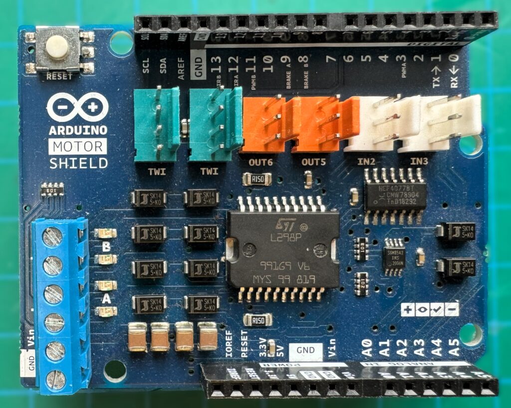
Motor Shield Pin Reference
| Function | Motor A Pin | Motor B Pin |
|---|---|---|
| Direction | 12 | 13 |
| Speed (PWM) | 3 | 11 |
| Brake | 9 | 8 |
For a deeper dive into motor drivers and how H-bridges work, see the full tutorial: Controlling DC Motors with L298N Dual H-Bridge and Arduino Motor Shield.
Troubleshooting your obstacle avoiding robot car
If your obstacle avoiding robot car is not behaving as expected, work through these common issues before assuming a hardware defect.
Common obstacle avoiding robot car problems and solutions
| Problem | Likely Cause | Solution |
|---|---|---|
| Robot does not move at all | No power, loose wiring, or brakes not released | First, check the power switch, battery voltage (should be ~12 V), and verify motor terminal connections. Make sure the code uploads without errors. |
| Only one motor runs | One motor not connected, or a broken wire | Instead, swap the working motor’s wires to the other terminal to test. Check solder joints on the motor. |
| Robot moves only in one direction | Motor wires swapped or direction pins wired incorrectly | Simply swap the two wires on the motor terminal that is running the wrong way (A+ and A−, or B+ and B−). |
| Ultrasonic sensor gives unstable or zero readings | Loose wiring, wrong pins, or object too close / too far | First, double-check Trig (pin 7) and Echo (pin 6) connections. The HC-SR04 range is approximately 2 cm to 400 cm. Add a small delay if readings fluctuate. |
Obstacle avoiding robot car sensor and power issues
| Problem | Likely Cause | Solution |
|---|---|---|
| Servo jitters or twitches | Insufficient power, servo connected to 3.3 V, or noisy power rail | First, make sure the servo VCC is connected to 5 V (not 3.3 V). Then, add a 100 µF capacitor across the servo power lines to smooth the supply. |
| Robot turns the wrong way | Left and right motors are swapped | Instead, swap the motor connections on the shield (move Motor A wires to Motor B terminals and vice versa), or swap the direction pin assignments in the code. |
| Robot reacts too late and crashes into obstacles | Distance threshold too low, or code delays too long | Therefore, increase the far threshold (e.g., from 40 cm to 50 cm) and reduce unnecessary delays in the loop. |
| Batteries drain very quickly | Motors drawing high current, or batteries not fully charged | First, use freshly charged NiMH batteries. Also, reduce motor speed if possible. Ensure no mechanical binding on wheels. |
| Arduino resets when motors start | Voltage drop from motor current draw | Instead, use a separate battery pack or add a large capacitor (470–1000 µF) across the motor shield power terminals. |
| Robot spins in circles | Both motors running in opposite directions, or one motor not turning | First, check direction pin assignments and then test each motor individually with a simple sketch before running the full code. |
Obstacle avoiding robot car FAQ
An obstacle avoiding robot car is a small autonomous vehicle that uses sensors (typically an ultrasonic sensor like the HC-SR04) to detect objects in its path and automatically changes direction to avoid collisions, all without human control.
The L293D motor shield is designed to plug directly into the Arduino Uno header. It will also fit an Arduino Mega, but not an Arduino Nano without an adapter. If you want to use a Nano, consider using a standalone L293D IC or an L298N module instead. See our L298N motor driver tutorial for an alternative approach.
Yes. The L298N is a common alternative that supports higher current. The wiring and pin assignments will differ since the L298N is a separate module rather than a shield, so you will need to adjust the code. Our DC motor control tutorial covers both options.
The sensor sends a short burst of ultrasonic sound (40 kHz) and measures how long it takes for the echo to return after bouncing off an object. The Arduino then converts this time into a distance in centimeters. For more details, see our ultrasonic sensor tutorial.
Without a servo, a fixed forward-facing sensor can only detect obstacles directly ahead. By mounting the sensor on a servo that sweeps from 30° to 150°, the robot gets a much wider field of view and can spot obstacles approaching from the sides before they are directly in front.
More obstacle avoiding robot car questions
For this project, we use 8 AA rechargeable batteries wired in series for roughly 12 V. The L293D motor shield accepts 5 V to 12 V on its power input and regulates power for the Arduino. You can also use a 2S or 3S LiPo battery (7.4 V to 11.1 V) as long as the voltage stays within the shield’s rated range.
No. The 3D-printed mounts make the build cleaner and more secure, but you can substitute them with hot glue, zip ties, double-sided tape, or small L-brackets from a hardware store.
Motor speed is controlled by the PWM value passed to analogWrite(). In the code, the forward cruising speed is set to 100 and the turning speed to 128 (out of a maximum of 255). Increase these values to go faster, or decrease them for slower, more controlled movement.
First, increase the far distance threshold from 40 cm to 50 cm or 60 cm. This makes the robot start slowing down earlier. Also check that the ultrasonic sensor is getting accurate readings by opening the Serial Monitor and printing the distance values for debugging.
Yes. You can add IR sensors on the sides for edge detection, a second ultrasonic sensor for rear detection, or even a line-following sensor on the bottom. Keep in mind that each additional sensor needs a free digital or analog pin on the Arduino and a small addition to the code.
Recommended Next Projects and Resources
Now that you have a working obstacle avoiding robot car, here are some ideas for your next build along with related OmArTronics tutorials.
- Arduino Programming Basics — strengthen your foundation if you are new to Arduino
- How to Control a Servo Motor Using Arduino — go deeper into servo positioning and sweep patterns
- Exploring Ultrasonic Sensors Using Arduino — learn advanced distance measurement techniques
- Controlling DC Motors with L298N and Arduino Motor Shield — understand H-bridges and motor drivers in depth
- Add Bluetooth or Wi-Fi control — combine obstacle avoidance with remote control using an HC-05 module or ESP8266
- Add a line-following mode — use IR sensors to follow a black line on the floor and switch between line-following and obstacle avoidance
- Upgrade to a 4WD chassis — add two more motors for better traction and stability on rough surfaces
Conclusion
You now have a working obstacle avoiding robot car built with an Arduino, an L293D motor shield, a servo motor, and an HC-SR04 ultrasonic sensor. Along the way, you learned how to wire DC motors, read ultrasonic distance data, control a servo for scanning, and write autonomous navigation logic. That covers the core skills of robotics: sensing the environment, making decisions, and controlling actuators.
From here, you can expand the robot with additional sensors, add wireless control, or tweak the obstacle avoidance algorithm for trickier environments. Happy building!
من أفضل ماشاهدت في هذا المجال بمافيه من توضيحات. سهل وميسر. تحياتي لكم أستاذي العزيز. أخوكم من سلطنة عمان
شكراً جزيلاً أخي سعيد على كلماتك الطيبة. سعيد جداً أن الشرح كان واضح ومفيد لك، هذا هو هدفي. تحياتي لك من ألمانيا إلى سلطنة عمان