Table of Contents
ToggleThe Principle of Ultrasonic Sensing
In this comprehensive tutorial, we’ll look at building a DIY radar system using an Arduino Uno, a servo motor and an HC-SR04 ultrasonic sensor. This setup not only includes basic electronics and programming, but also includes custom 3D-printed mounts for both the servo and the sensor, increasing the mechanical robustness and functionality of the project. This radar system will scan the environment and display detected objects on a visual interface, simulating a radar screen.
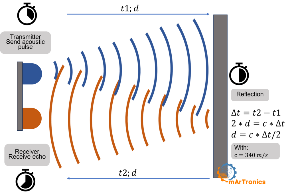
An ultrasonic sensor works by sending an ultrasonic sound wave (a frequency higher than humans can hear) to an object and then listening for the echo of that wave. By calculating the time between sending the signal and receiving the echo, the sensor can determine the distance to an object. This method is similar to how bats navigate in the dark.
An ultrasonic sensor typically comprises two main components: a transmitter and a receiver. The transmitter emits high-frequency sound waves, which travel through the air until they encounter an object. Once these sound waves hit the object, they reflect back towards the sensor, where the receiver detects them as an echo.
- Transmission of Sound Waves: The transmitter side of the sensor emits an acoustic pulse, a sound wave at a frequency that is generally above the human hearing range, usually around 40 kHz. This sound wave spreads out in a cone-shaped manner from the sensor.
- Reflection of Sound Waves: Once the emitted sound wave encounters an object, it bounces back towards the sensor. This returned signal is often referred to as the echo. The nature of the reflected sound wave can be influenced by the shape, size, and material of the object it encounters.
- Reception of Echo: The receiver part of the sensor then detects this echo. By precisely timing how long it takes for the echo to return, the sensor can calculate the distance to the object. This calculation is based on the speed of sound in air, which is approximately 340 meters per second under standard conditions.
- Distance Calculation: The distance to the object is typically calculated by measuring the time interval between when the sound wave was emitted and when the echo was received. Using the formula
Distance =1/2×Time×Speed of Sound, the sensor computes the distance. The factor of 1/2 is used because the sound wave travels to the object and then back to the sensor, hence covering the distance twice.
The most common ultrasonic sensor used in DIY projects is the HC-SR04. This sensor offers excellent distance detection, is very affordable and is widely available. The HC-SR04 can measure distances from 2cm to 400cm with an accuracy of up to 3mm, making it suitable for a wide range of application
Materials and tools needed to build a DIY Arduino radar
- Arduino Uno
- HC-SR04 ultrasonic sensor
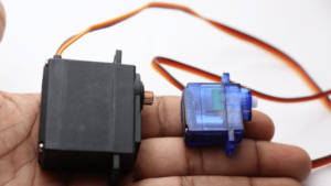
- Servo motor
- Jumper wires
- Breadboard
- 3D Printer with 3D printing filament
- Computer with Arduino IDE and Processing IDE installed
Designing 3D mounts
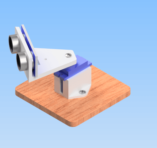
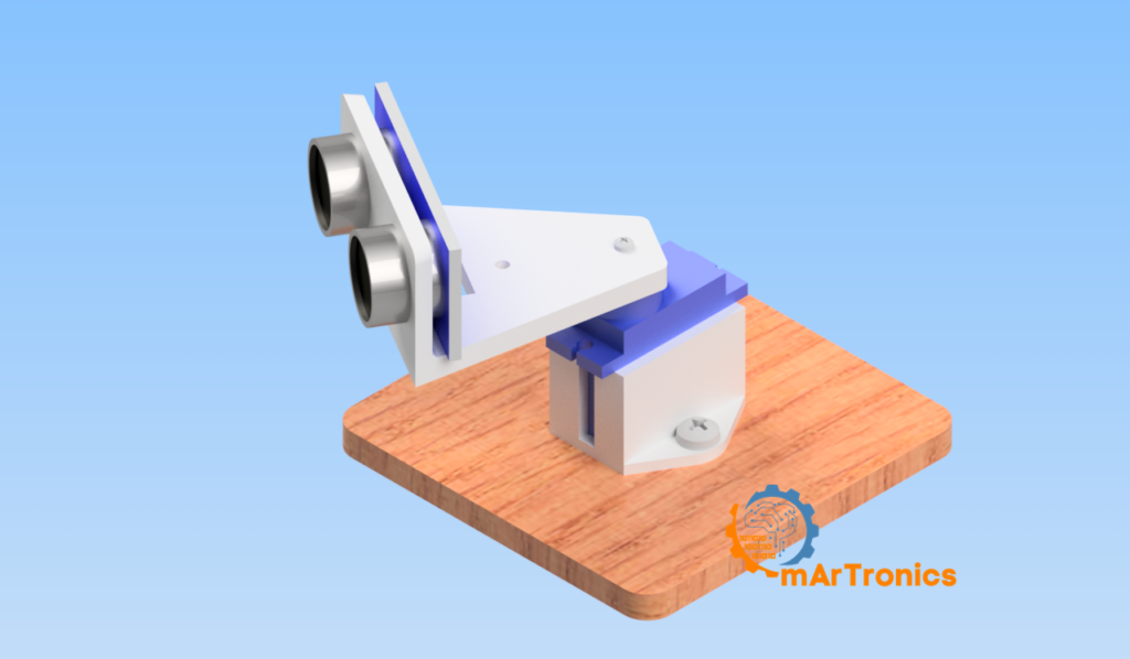
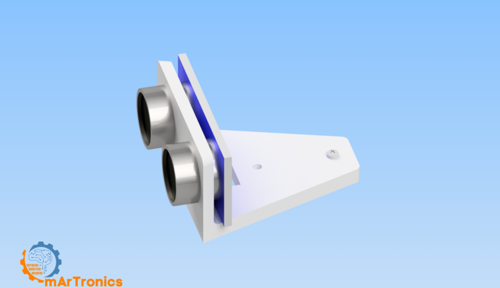
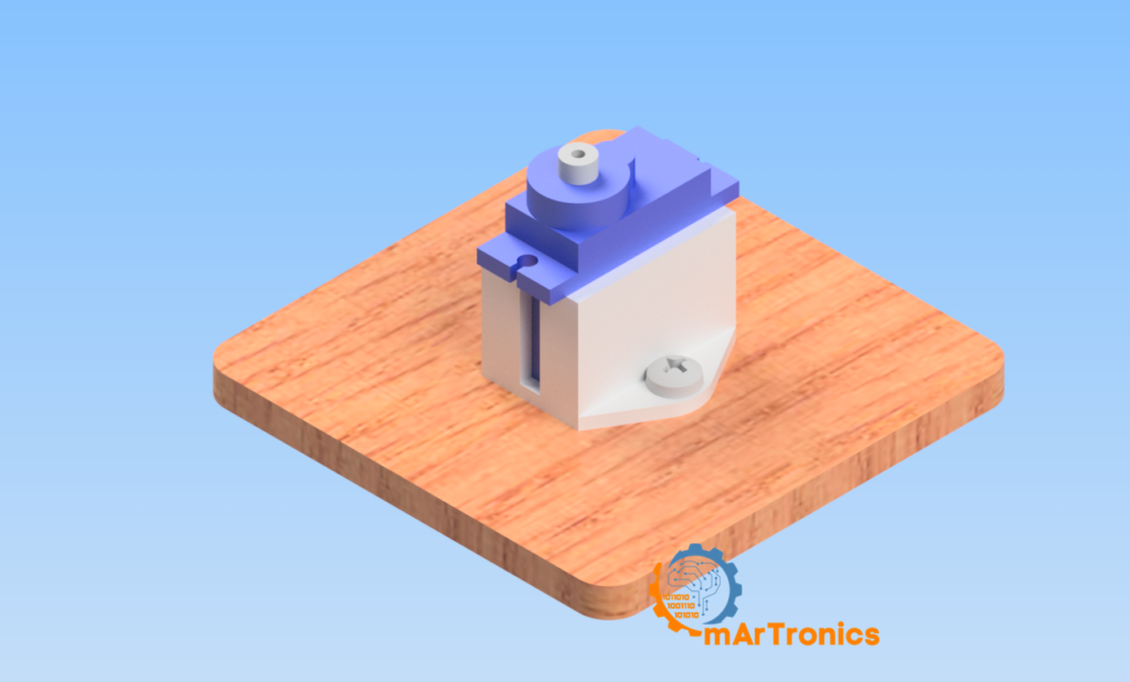
Before assembling the electronics, start by designing custom mounts for the ultrasonic sensor and servo motor. These mounts can be created using CAD software such as Autodesk Fusion 360.
Sensor mount: Design a bracket that fits snugly into the HC-SR04 and has features that allow it to be easily attached to the servo motor. Make sure there are openings for the sensor’s ultrasonic transmitters and receivers.
Mount the servo: Create a base that will securely hold the servo motor and can be placed on a stable platform. The top of the servo mount should allow the sensor mount to fit seamlessly and rotate freely.
Once your designs are finalised, use a 3D printer to print the mounts using a strong filament such as PLA or ABS.
Assembling the hardware
After printing your mounts:
- Mount the ultrasonic sensor: Secure the HC-SR04 in its 3D printed holder. Make sure that no part of the holder obstructs the ultrasonic signals.
- Attach the servo motor to its bracket: Place the servo in its socket, making sure it’s firmly seated and that the wiring can extend to the Arduino without strain.
- Assemble the components: Attach the sensor mount to the servo, typically on the horn of the servo, using small screws or a snap-on design that allows the sensor to rotate with the servo’s movements.
Electronic configuration and wiring
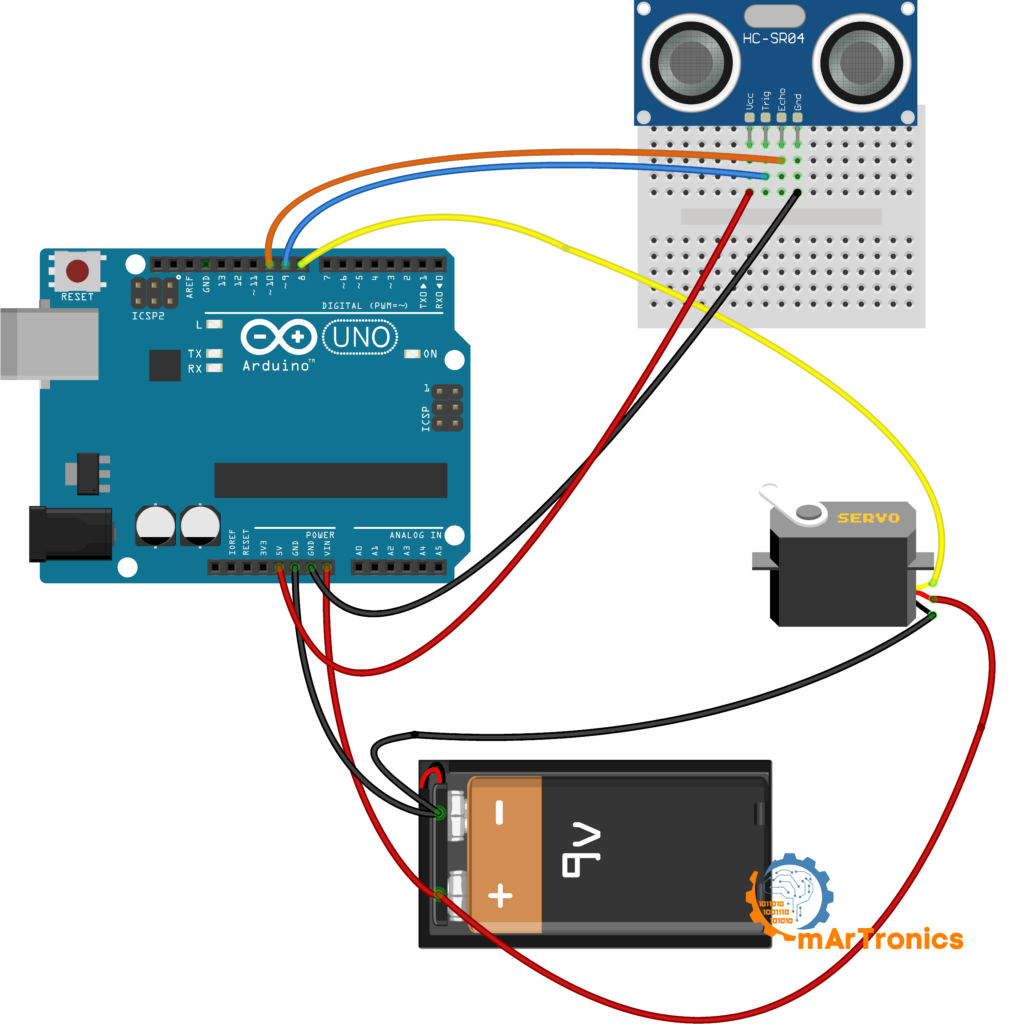
- Servo connections:
Signal Pin: Connect to pin 8 on the Arduino.
Power (VCC) and Ground (GND): Connect to 5V and GND on the Arduino. - Ultrasonic sensor connections:
VCC: Also to Arduino’s 5V.
GND: To one of the GND pins on the Arduino.
TRIG: To pin 9 on the Arduino.
ECHO: To pin 10 on the Arduino.
Use a breadboard to make connections easier and to manage any additional components or future expansions.
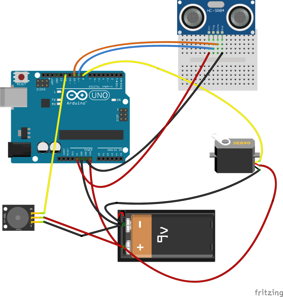
Electronic configuration with buzzer
Programming the Arduino
Once everything is connected, you’ll need to program the Arduino to read the signals from the ultrasonic sensor:
/**
 * Author: Omar Draidrya
 * Date: 2024/05/09
 * This code controls a servo motor and measures distance using an ultrasonic sensor.
 */

#include <Servo.h>

Servo myServo;                  // Create a servo object
const int trigPin = 9;          // Trigger pin of the ultrasonic sensor
const int echoPin = 10;         // Echo pin of the ultrasonic sensor
long duration;                  // Variable to store the duration of the pulse
int distance;                   // Variable to store the distance calculated

void setup() {
    pinMode(trigPin, OUTPUT);   // Set the trigger pin as an output
    pinMode(echoPin, INPUT);    // Set the echo pin as an input
    Serial.begin(9600);         // Initialize serial communication
    myServo.attach(8);          // Attach the servo on pin 8 to the servo object
}

void loop() {
    for (int i = 15; i <= 165; i++) {  // Sweep the servo from 15 to 165 degrees
        myServo.write(i);              // Move the servo to position 'i'
        delay(30);                     // Wait for 30 milliseconds
        distance = calculateDistance();// Calculate the distance
        Serial.print(i);               // Print the servo position
        Serial.print(",");             // Print a comma
        Serial.print(distance);        // Print the distance
        Serial.print(".");             // Print a period
    }

    for (int i = 165; i > 15; i--) {   // Sweep the servo from 165 to 15 degrees
        myServo.write(i);              // Move the servo to position 'i'
        delay(30);                     // Wait for 30 milliseconds
        distance = calculateDistance();// Calculate the distance
        Serial.print(i);               // Print the servo position
        Serial.print(",");             // Print a comma
        Serial.print(distance);        // Print the distance
        Serial.print(".");             // Print a period
    }
}

int calculateDistance() {
    digitalWrite(trigPin, LOW);        // Clear the trigger pin
    delayMicroseconds(2);              // Wait for 2 microseconds
    digitalWrite(trigPin, HIGH);       // Set the trigger pin high
    delayMicroseconds(10);             // Wait for 10 microseconds
    digitalWrite(trigPin, LOW);        // Set the trigger pin low
    duration = pulseIn(echoPin, HIGH); // Read the echo pin and return the duration of the pulse
    distance = duration * 0.034 / 2;   // Calculate the distance
    return distance;                   // Return the distance
}
Programming the Arduino buzzer
/**
 * Author: Omar Draidrya
 * Date: 2024/05/09
 * This code controls a servo motor, measures distance using an ultrasonic sensor, and activates a buzzer when an obstacle is close.
 */

#include <Servo.h>

Servo myServo;                   // Create a servo object
const int trigPin = 9;           // Trigger pin of the ultrasonic sensor
const int echoPin = 10;          // Echo pin of the ultrasonic sensor
const int buzzerPin = 12;        // Pin for the buzzer
long duration;                   // Variable to store the duration of the pulse
int distance;                    // Variable to store the distance calculated

void setup() {
    pinMode(trigPin, OUTPUT);    // Set the trigger pin as an output
    pinMode(echoPin, INPUT);     // Set the echo pin as an input
    pinMode(buzzerPin, OUTPUT);  // Set the buzzer pin as an output
    Serial.begin(9600);          // Initialize serial communication
    myServo.attach(8);           // Attach the servo on pin 8 to the servo object
}

void loop() {
    for (int i = 15; i <= 165; i++) {  // Sweep the servo from 15 to 165 degrees
        myServo.write(i);              // Move the servo to position 'i'
        delay(30);                     // Wait for 30 milliseconds
        distance = calculateDistance();// Calculate the distance
        Serial.print(i);               // Print the servo position
        Serial.print(",");             // Print a comma
        Serial.print(distance);        // Print the distance
        Serial.print(".");             // Print a period

        if (distance <= 10) {          // If the distance is less than or equal to 10 cm
            tone(buzzerPin, 2000);     // Activate the buzzer with a frequency of 2000 Hz
        } else {
            noTone(buzzerPin);         // Deactivate the buzzer
        }
    }

    for (int i = 165; i > 15; i--) {   // Sweep the servo from 165 to 15 degrees
        myServo.write(i);              // Move the servo to position 'i'
        delay(30);                     // Wait for 30 milliseconds
        distance = calculateDistance();// Calculate the distance
        Serial.print(i);               // Print the servo position
        Serial.print(",");             // Print a comma
        Serial.print(distance);        // Print the distance
        Serial.print(".");             // Print a period

        if (distance <= 10) {          // If the distance is less than or equal to 10 cm
            tone(buzzerPin, 2000);     // Activate the buzzer with a frequency of 2000 Hz
        } else {
            noTone(buzzerPin);         // Deactivate the buzzer
        }
    }
}

int calculateDistance() {
    digitalWrite(trigPin, LOW);        // Clear the trigger pin
    delayMicroseconds(2);              // Wait for 2 microseconds
    digitalWrite(trigPin, HIGH);       // Set the trigger pin high
    delayMicroseconds(10);             // Wait for 10 microseconds
    digitalWrite(trigPin, LOW);        // Set the trigger pin low
    duration = pulseIn(echoPin, HIGH); // Read the echo pin and return the duration of the pulse
    distance = duration * 0.034 / 2;   // Calculate the distance
    return distance;                   // Return the distance
}
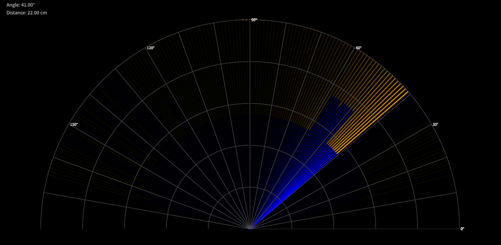
Visualisation with Processing:
Processing IDE is a flexible software sketchbook and language for learning to code in the context of the visual arts. It’s open source and has been developed by artists and designers as an easy-to-use alternative to more complex programming environments. The IDE is particularly suited to creating visual and interactive projects. Processing provides a straightforward approach to integrating real-world or digital input and visualising or interacting with it in a variety of ways. It’s often used in educational settings to introduce programming because it provides immediate visual feedback and encourages a deeper understanding of how code affects output. This makes Processing an excellent tool for visualising data from sensors in Arduino projects, such as a radar interface, where understanding spatial relationships and movement is crucial.
To visualise the radar interface, we’ll use the Processing IDE, which can interpret and display data sent via the Arduino’s serial output. Here is a Processing code to display the radar screen:
/**
 * Date: 2024/05/09
 * This code creates a radar-like display using Processing, receiving data from a serial port.
 */

import processing.serial.*;

Serial communicationPort;    // Serial communication port
String serialData = "";      // Variable to store serial data
float scanAngle = 0;         // Variable to store scan angle
float scanDistance = 0;      // Variable to store scan distance
int radarRadius = 800;       // Radar radius
int maxDistance = 40;        // Maximum display distance in cm

void setup() {
    size(1920, 1080);                // Set the size of the window
    smooth();                        // Enable anti-aliasing
    String portName = Serial.list()[0]; // Get the first serial port (adjust index as needed)
    communicationPort = new Serial(this, portName, 9600); // Initialize serial communication
    communicationPort.bufferUntil('.'); // Set the buffer until '.' character
    background(0);                   // Set the background to black
}

void draw() {
    drawRadarBackground(); // Draw the radar background
    if (serialData.length() > 0) {
        parseSerialData(); // Parse the incoming serial data
        drawDetection();   // Draw the detected object
    }
    displayInfo(scanDistance, scanAngle); // Update display information
}

void drawRadarBackground() {
    pushMatrix();
    translate(width / 2, height - 200); // Position the radar
    noFill();
    stroke(80);            // Gray grid lines
    strokeWeight(1);
    for (int i = 0; i < 5; i++) {
        float r = radarRadius * (i + 1) / 5.0;
        arc(0, 0, r * 2, r * 2, PI, TWO_PI); // Draw radar arcs
    }
    for (int i = 0; i < 180; i += 10) {
        float x = radarRadius * cos(radians(i));
        float y = radarRadius * sin(radians(i));
        line(0, 0, x, -y); // Draw radar lines
        if (i % 30 == 0) {
            fill(255);
            textSize(16);
            text(i + "°", x + 5, -y + 5); // Display angle labels
        }
    }
    popMatrix();
}

void parseSerialData() {
    String[] tokens = serialData.split(",");
    if (tokens.length >= 2) {
        scanAngle = float(tokens[0]);   // Parse the scan angle
        scanDistance = float(tokens[1]);// Parse the scan distance
    }
}

void drawDetection() {
    float angle = radians(scanAngle);
    float distance = scanDistance;
    float x = distance * 20; // Scale distance for display
    float fullX = radarRadius * cos(angle);
    float fullY = radarRadius * sin(angle);

    pushMatrix();
    translate(width / 2, height - 200);
    strokeWeight(4);

    // Fade effect
    noStroke();
    fill(0, 20);  // Semi-transparent black overlay
    rect(-radarRadius, -radarRadius, radarRadius * 2, radarRadius);

    // Detection line
    if (distance > 0 && distance <= maxDistance) {
        stroke(0, 0, 255);  // Blue for detected area
        line(0, 0, x * cos(angle), -x * sin(angle));
        stroke(255, 165, 0);  // Orange for the remaining area
        line(x * cos(angle), -x * sin(angle), fullX, -fullY);
    } else {
        stroke(0, 0, 255);  // Blue if no detection
        line(0, 0, fullX, -fullY);
    }
    popMatrix();
    serialData = ""; // Clear data after drawing
}

void displayInfo(float distance, float angle) {
    fill(0); // Black background for text area
    noStroke();
    rect(10, 10, 260, 80); // Area for text

    fill(255);
    textSize(20);
    text("Angle: " + nf(angle, 1, 2) + "°", 30, 30); // Display angle information
    text("Distance: " + nf(distance, 1, 2) + " cm", 30, 60); // Display distance information
}

void serialEvent(Serial p) {
    serialData = p.readStringUntil('.'); // Read serial data until '.' character
    serialData = serialData.substring(0, serialData.length() - 1); // Remove the '.' character
}
Calibrating and testing
Once you’ve set up the software, it’s time to calibrate and test your radar system. Power up the Arduino and look at the Processing sketch to see how well the radar detects objects. Adjust the range and sensitivity as required by changing the parameters in the Arduino sketch.
Conclusion
This project demonstrates how to combine a servo motor and an ultrasonic sensor to create a simple radar system using Arduino. This setup scans the environment and visualises the data in real time, making it ideal for educational purposes, hobby projects, and even practical applications in robotics and sensing.

