
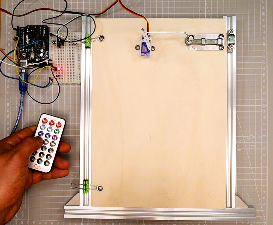
Want to control real hardware with a TV-style remote? In this Arduino IR remote tutorial, you will build a wireless LED controller using an infrared remote and a KY-022 receiver module, then upgrade the same circuit to operate a servo-driven door. The project is structured in two progressive stages so you can learn at your own pace: first a simple LED toggle, then a mechanical door that opens and closes on command.
Specifically, this tutorial builds on the door mechanism from our Arduino Password Door Lock project. If you already built that servo latch, you can reuse it here and swap keypad control for IR remote control. If you are new to servo motors, our servo motor with joystick and OLED tutorial is a great companion guide.
What You’ll Build
- LED-only controller (Part 1): Press one remote button to toggle an LED on pin D8. This teaches IR decoding, repeat filtering, and basic digital output.
- LED + Servo door upgrade (Part 2): Add two more remote buttons to OPEN and CLOSE a micro servo door on pin D9. The LED automatically mirrors the door state (ON when open, OFF when closed).
How the System Works
In particular, understanding the signal chain helps you debug problems and adapt the project to your own needs. Here is what happens each time you press a button on the remote:
- Remote transmits an IR signal. When you press a button, the remote flashes its infrared LED with a modulated 38 kHz carrier. Each button sends a unique code defined by the NEC (or similar) protocol.
- Next, the KY-022 receiver demodulates the signal. The IR receiver module strips away the 38 kHz carrier and outputs a clean digital pulse train on its OUT pin, which is connected to Arduino pin D2.
- IRremote library decodes the frame. The library interrupt-captures the pulse timings, identifies the protocol, and exposes the decoded
commandbyte and the fulldecodedRawDataword. It also flags repeat frames that the remote sends while you hold a button down. - Arduino acts on the decoded command. Your sketch compares the received command against stored values. In the LED-only build, a match toggles the LED. In the servo upgrade, OPEN and CLOSE commands move the servo to the target angle while the LED follows the door state.
Because the architecture is identical for both stages, upgrading from LED-only to LED + servo is simply a matter of adding wiring and mapping two extra remote buttons.
Components Required
In summary, the table below lists every part you need. Components marked with a check in the LED-only column are enough for Part 1. Add the remaining parts when you are ready for the servo door upgrade in Part 2.
| Component | LED-Only (Part 1) | Servo Upgrade (Part 2) | Notes |
|---|---|---|---|
| Arduino Uno (or Nano) | Yes | Yes | Any ATmega328-based board works |
| IR receiver module (KY-022 / VS1838B / TSOP1838) | Yes | Yes | 3-pin module; OUT goes to D2 |
| IR remote (kit remote) | Yes | Yes | Most NEC-protocol remotes work |
| LED (any color) | Yes | Yes | Standard 5 mm through-hole |
| 220 ohm resistor | Yes | Yes | Current-limiting resistor for the LED |
| Breadboard and jumper wires | Yes | Yes | Half-size breadboard is enough |
| Micro servo (SG90 or MG90S) | No | Yes | SG90 for lightweight doors |
| External 5 V power supply (1 A or more) | No | Yes | Prevents brownouts; do not power the servo from Arduino 5 V |
| Door latch or mechanism | No | Yes | 3D-printed, wire, or cardboard |
Power tip: Servo motors draw large current spikes when they start moving. Importantly, always power the servo from a separate 5 V supply and connect the supply GND to the Arduino GND (common ground). Without this connection, you will experience resets, jitter, and unreliable IR reception.
Part 1 — Arduino IR Remote LED (LED-Only Build)
Circuit Diagram — LED-Only Wiring
To build the circuit, wire the IR receiver and LED to the Arduino as shown in the table and diagram below. The IR receiver OUT pin connects to D2 (the IRremote library default). The LED anode connects through a 220 ohm resistor to D8.
| Component | Pin / Terminal | Connects To |
|---|---|---|
| IR receiver (KY-022) | OUT (S) | Arduino D2 |
| IR receiver (KY-022) | VCC (+) | Arduino 5 V |
| IR receiver (KY-022) | GND (-) | Arduino GND |
| LED anode (long leg) | Anode (+) | 220 ohm resistor, then to Arduino D8 |
| LED cathode (short leg) | Cathode (-) | Arduino GND |
In particular, note this beginner tip — LED polarity: The longer leg of the LED is the anode (positive). The shorter leg is the cathode (negative, often marked with a flat edge on the LED body). The 220 ohm resistor can go on either side of the LED; it limits current to protect the LED and the Arduino pin. If the LED does not light up, try flipping it around.
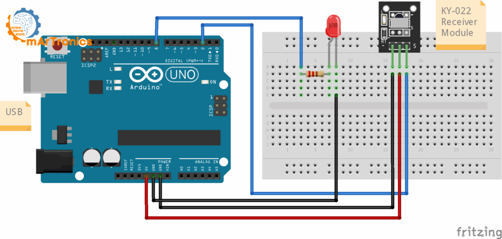
LED-only wiring diagram: KY-022 IR receiver connected to D2, LED with 220 ohm resistor connected to D8 on Arduino Uno.
Step 1 — Install the IRremote Library
First, open the Arduino IDE and go to Tools > Manage Libraries. Search for IRremote by Arduino-IRremote and install the latest version. This tutorial uses the modern IRremote 3.x+ API with IRremote.hpp and IrReceiver.begin().
The library handles all the low-level timing and protocol detection. After installing, you can include it and initialize the receiver with two lines:
#include <IRremote.hpp>
// ...
IrReceiver.begin(pin, ENABLE_LED_FEEDBACK);
For further reference, the official IRremote GitHub repository has full documentation if you want to explore advanced features.
Step 2 — Scan Your Remote (IR Code Scanner)
Every remote sends different codes, even if they look identical. Therefore, before writing the final sketch you must scan your specific remote to find out what code each button sends. This step is essential because the example values in the final code (0x45, 0x46, etc.) almost certainly do not match your remote.
Upload the scanner sketch below, open Serial Monitor at 115200 baud, and press each remote button a few times. We use 115200 baud (instead of the common 9600) because the IRremote library prints detailed output that benefits from the faster speed.
// IR Code Scanner (IRremote >= 3.x)
#include <IRremote.hpp>
const uint8_t IR_RECEIVE_PIN = 2;
void setup(){
  Serial.begin(115200);
  IrReceiver.begin(IR_RECEIVE_PIN, ENABLE_LED_FEEDBACK);
  Serial.println(F("IR Scanner ready. Press remote buttons..."));
}
void loop(){
  if(IrReceiver.decode()){
    IrReceiver.printIRResultShort(&Serial); // concise one-liner
    Serial.print(F("Protocol="));   Serial.print(IrReceiver.decodedIRData.protocol);
    Serial.print(F("  Command=0x"));Serial.print(IrReceiver.decodedIRData.command, HEX);
    Serial.print(F("  RAW=0x"));    Serial.println(IrReceiver.decodedIRData.decodedRawData, HEX);
    IrReceiver.resume();
  }
}
What to look for: Each button press prints a Command value and a RAW value. With most NEC-protocol kit remotes, the command byte is short and stable across presses. Write it down. If you notice that command changes randomly or shows 0x00, use the full 32-bit decodedRawData (RAW) value instead. The RAW value is always available as a fallback regardless of protocol.
Pick one button for LED toggle. Additionally, if you plan to do the servo upgrade, also pick separate buttons for OPEN and CLOSE. Finally, write down all three values before you continue.
Step 3 — Arduino IR Remote LED Code (Final LED-Only Sketch)
Next, replace CMD_LED_TOGGLE with the command value you found in the scanner. If your remote’s command byte was unreliable, uncomment the RAW line and use RAW_LED_TOGGLE instead.
// IR Code Scanner (IRremote >= 3.x)
#include <IRremote.hpp>
const uint8_t IR_RECEIVE_PIN = 2; // IR OUT → D2
const uint8_t LED_PIN        = 8; // LED → 220Ω → D8
// Replace with your scanned value:
const uint32_t CMD_LED_TOGGLE = 0x45;  // example NEC command
// Alternative if command is unstable:
// const uint32_t RAW_LED_TOGGLE = 0x00FFA25D; // example 32-bit RAW
bool ledOn = false;
void setLED(bool on){
  ledOn = on;
  digitalWrite(LED_PIN, ledOn ? HIGH : LOW);
}
void setup(){
  pinMode(LED_PIN, OUTPUT);
  setLED(false);
  Serial.begin(115200);
  IrReceiver.begin(IR_RECEIVE_PIN, ENABLE_LED_FEEDBACK);
  Serial.println(F("LED-only mode. Press your toggle key."));
}
void loop(){
  if(!IrReceiver.decode()) return;
  if(!(IrReceiver.decodedIRData.flags & IRDATA_FLAGS_IS_REPEAT)){
    uint32_t cmd = IrReceiver.decodedIRData.command;
    uint32_t raw = IrReceiver.decodedIRData.decodedRawData;
    if (cmd == CMD_LED_TOGGLE)        setLED(!ledOn);
    // else if (raw == RAW_LED_TOGGLE) setLED(!ledOn); // use if needed
    Serial.print(F("[IR] cmd=0x")); Serial.print(cmd, HEX);
    Serial.print(F(" raw=0x"));     Serial.println(raw, HEX);
  }
  IrReceiver.resume();
}
How the LED-Only Code Works
Here is a breakdown of the key parts of the sketch so you understand what each section does and can modify it confidently:
- IRDATA_FLAGS_IS_REPEAT: When you hold a button on an IR remote, the remote continuously sends repeat frames at short intervals. Without filtering, a single long press would toggle the LED many times. The line
if(!(IrReceiver.decodedIRData.flags & IRDATA_FLAGS_IS_REPEAT))ignores these repeat frames so only the first press counts. - command vs. decodedRawData: The
commandfield contains the short protocol-specific button code (usually 1 byte for NEC). ThedecodedRawDatafield holds the full 32-bit raw frame including address and command. Usecommandwhen it is stable for your remote. Fall back todecodedRawDataifcommandreturns inconsistent values or zero. - setLED() helper function: Centralizing the LED logic in
setLED()means every part of the program changes the LED the same way. This matters more in the servo upgrade where the LED must mirror the door state. By callingsetLED()everywhere instead ofdigitalWrite()directly, you avoid bugs where the LED and the internal state variable get out of sync. - Replacing the example value: The value
0x45is just an example. Open the scanner sketch from Step 2, press the button you want to use, and replace0x45with theCommandhex value shown in Serial Monitor. If you need the RAW fallback, uncomment the RAW line and replace0x00FFA25Dwith your scanned RAW value.
Part 2 — Upgrade to Arduino IR Remote LED + Servo Door
Now extend the build: specifically, keep all the LED logic from Part 1, add a servo motor, and map two more remote keys (OPEN and CLOSE). The LED will automatically show the door status: ON means the door is open, OFF means it is closed.
Servo Wiring (Add to LED-Only Circuit)
First, keep all the IR receiver and LED wiring from Part 1. Then add the servo connections listed in the table below.
| Component | Pin / Wire | Connects To |
|---|---|---|
| Servo (SG90) | Signal (orange/yellow) | Arduino D9 (PWM) |
| Servo (SG90) | VCC (red) | External 5 V supply (+) |
| Servo (SG90) | GND (brown/black) | External 5 V supply (-) |
| External supply GND | GND | Arduino GND (common ground) |
Why use an external 5 V supply? Importantly, the Arduino’s onboard 5 V regulator can only provide around 500 mA. A servo motor draws 200-700 mA in normal operation and even higher during stall. Drawing this much current through the Arduino causes voltage drops that reset the board, corrupt IR reception, and make the servo jitter. A separate 5 V 1 A (or higher) supply avoids all of these problems.
Why common ground is required: Furthermore, the Arduino and the external supply must share a ground connection. Without it, the servo signal wire has no reference voltage and the servo will not respond or will behave erratically.
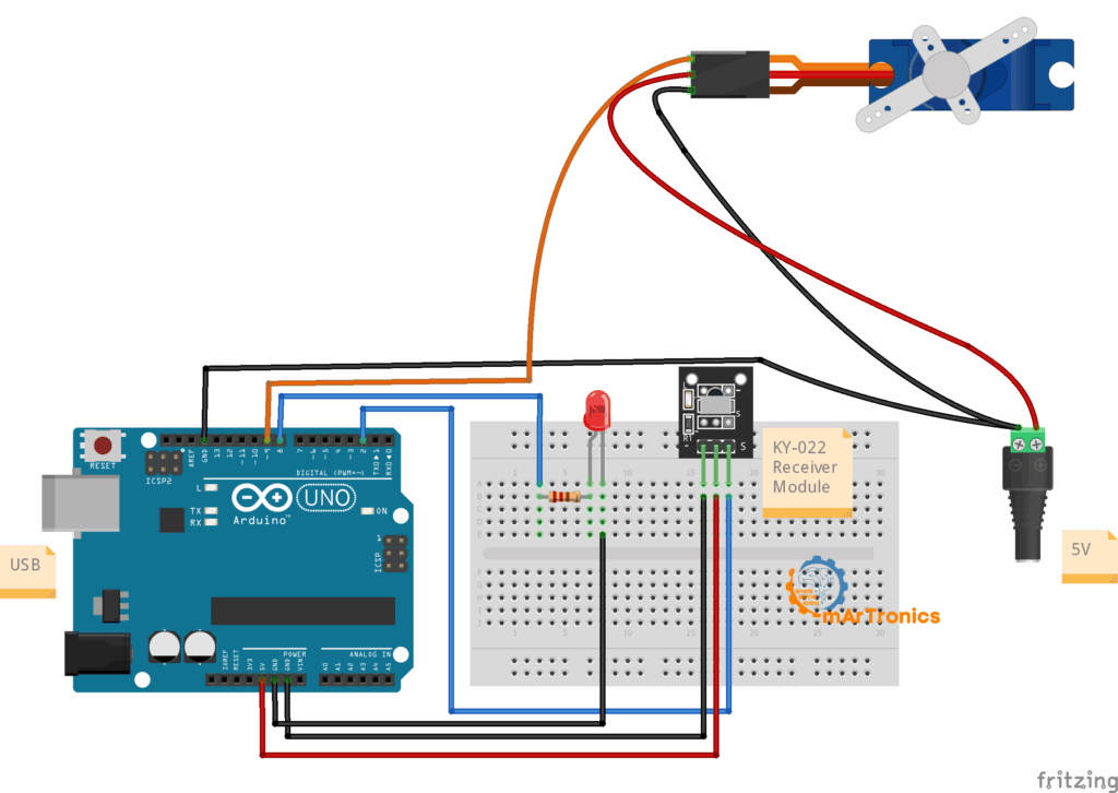
Full wiring diagram for the LED + servo door upgrade: KY-022 on D2, LED on D8, SG90 servo on D9 powered by an external 5 V supply with common ground to the Arduino.
Combined Code — LED + Servo Door
Before uploading, replace CMD_LED_TOGGLE, CMD_OPEN, and CMD_CLOSE with the three values you recorded in the scanner step. If your remote needs the RAW fallback, uncomment those lines and fill in your values.
Full Combined Sketch
// Arduino IR remote LED + Servo Door (IRremote >= 3.x)
#include <IRremote.hpp>
#include <Servo.h>
const uint8_t IR_RECEIVE_PIN = 2;   // IR OUT → D2
const uint8_t LED_PIN        = 8;   // LED → 220Ω → D8
const uint8_t SERVO_PIN      = 9;   // Servo signal → D9
// === Replace with your scanned values ===
const uint32_t CMD_LED_TOGGLE = 0x45; // LED toggle
const uint32_t CMD_OPEN       = 0x46; // door open
const uint32_t CMD_CLOSE      = 0x47; // door close
// RAW fallback (uncomment if needed):
// const uint32_t RAW_LED_TOGGLE = 0x00FFA25D;
// const uint32_t RAW_OPEN       = 0x00FF629D;
// const uint32_t RAW_CLOSE      = 0x00FF22DD;
const int OPEN_ANGLE  = 20;  // tune to your linkage
const int CLOSE_ANGLE = 90;
const int STEP_DEG    = 2;
const int STEP_MS     = 10;
Servo door;
bool ledOn = false;
int  curAngle = CLOSE_ANGLE;
void setLED(bool on){
  ledOn = on;
  digitalWrite(LED_PIN, on ? HIGH : LOW);
}
void moveServoTo(int target){
  int dir = (target > curAngle) ? 1 : -1;
  while(curAngle != target){
    curAngle += dir * STEP_DEG;
    if((dir > 0 && curAngle > target) || (dir < 0 && curAngle < target)) curAngle = target;
    door.write(curAngle);
    delay(STEP_MS);
  }
}
void setDoorOpen(bool open){
  moveServoTo(open ? OPEN_ANGLE : CLOSE_ANGLE);
  setLED(open); // LED shows door status: ON=open, OFF=closed
}
void setup(){
  Serial.begin(115200);
  pinMode(LED_PIN, OUTPUT);
  setLED(false);
  door.attach(SERVO_PIN);
  door.write(CLOSE_ANGLE);
  IrReceiver.begin(IR_RECEIVE_PIN, ENABLE_LED_FEEDBACK);
  Serial.println(F("LED + Servo mode. Use TOGGLE / OPEN / CLOSE keys."));
}
void loop(){
  if(!IrReceiver.decode()) return;
  if(!(IrReceiver.decodedIRData.flags & IRDATA_FLAGS_IS_REPEAT)){
    uint32_t cmd = IrReceiver.decodedIRData.command;
    uint32_t raw = IrReceiver.decodedIRData.decodedRawData;
    if (cmd == CMD_LED_TOGGLE) setLED(!ledOn);
    else if (cmd == CMD_OPEN)  setDoorOpen(true);
    else if (cmd == CMD_CLOSE) setDoorOpen(false);
    // RAW fallback:
    // if (raw == RAW_LED_TOGGLE) setLED(!ledOn);
    // if (raw == RAW_OPEN)       setDoorOpen(true);
    // if (raw == RAW_CLOSE)      setDoorOpen(false);
  }
  IrReceiver.resume();
}
How the Servo Door Code Works
Overall, the combined sketch adds three important features on top of the LED-only version. Each one addresses a specific challenge of moving a physical mechanism reliably:
- OPEN_ANGLE and CLOSE_ANGLE: These constants define how far the servo rotates for the open and closed positions. The default values (20 and 90 degrees) are starting points. You should tune them to match your specific door linkage. Test with the servo detached first, then attach the horn and adjust until the latch fully opens and fully closes.
- Small-step movement (moveServoTo): Instead of jumping directly to the target angle, the servo moves in 2-degree increments with a 10 ms delay between steps. This gradual movement reduces mechanical stress on the servo gears, lowers the current spike, and makes the door motion quieter and smoother. You can increase
STEP_DEGfor faster movement or decrease it for even smoother motion. - LED mirrors door state: The
setDoorOpen()function callssetLED()after moving the servo, so the LED is always in sync with the door position. ON means the door is open, OFF means it is closed. You can still toggle the LED independently with the LED toggle button if you want.
How to Test and Tune the Build
To verify everything works correctly, follow this step-by-step sequence to bring up the project safely and avoid frustration:
Step-by-Step Testing Sequence
- Test the scanner first. Upload the scanner sketch from Step 2. Open Serial Monitor at 115200. Press each remote button and confirm you see consistent output. If nothing appears, check your wiring and make sure the IR receiver OUT goes to D2.
- Verify LED-only functionality. Upload the LED-only sketch from Step 3. Press your chosen toggle button. The LED on D8 should turn on with the first press and off with the second. Watch Serial Monitor for the decoded command values to confirm they match your expectations.
- Test the servo without the door mechanism. Before attaching the servo to any door or latch, upload the combined sketch and test with the servo loose on the desk. Press OPEN and CLOSE and verify the servo rotates smoothly between the two angles. This prevents stripped gears if the angles are wrong.
- Tune open and close angles. Adjust
OPEN_ANGLEandCLOSE_ANGLEin the code until the servo arm reaches the correct positions for your latch. Re-upload and test after each change. Small changes of 5-10 degrees at a time are safest. - Attach the mechanism and final test. Mount the servo horn to your door latch. Run the combined sketch and verify that the door opens, closes, and that the LED correctly mirrors the state.
Troubleshooting
If something is not working, check these common issues:
| Problem | Likely Cause | Solution |
|---|---|---|
| No serial output appears | Wrong baud rate or wiring error | Set Serial Monitor to 115200. Check that IR receiver OUT is connected to D2 and the module has 5 V and GND. |
| Remote button does not trigger reliably | Weak signal, distance, or angle | Point the remote directly at the receiver from within 3 meters. Remove bright IR sources (sunlight, some lamps) that can overload the receiver. |
| Command value changes unexpectedly | Protocol mismatch or noisy signal | Use the RAW (decodedRawData) fallback instead of command. Some remotes use protocols where the command byte varies. |
| LED does not toggle | Wrong command value in code | Open the scanner sketch, press the button, and compare the hex value to what you have in the LED-only sketch. Also check LED polarity (flip it if needed). |
| Long presses cause repeated toggling | Repeat filtering missing or not working | Make sure the IRDATA_FLAGS_IS_REPEAT check is present in your loop. Do not remove the flag check. |
| Servo jitters or buzzes | Insufficient power or noisy signal | Power the servo from an external 5 V supply with common ground. Ensure the signal wire is short and not near power cables. |
| Servo does not move at all | Wrong pin, no power, or wrong command | Verify the signal wire is on D9. Check that the external supply is on and GND is connected to Arduino GND. Verify OPEN and CLOSE command values match your scanner output. |
| Servo moves the wrong direction | OPEN_ANGLE and CLOSE_ANGLE swapped | Swap the values of OPEN_ANGLE and CLOSE_ANGLE in the code and re-upload. |
| Arduino resets when servo moves | Servo drawing too much current from Arduino | This is the most common problem. Use an external 5 V supply for the servo. The Arduino 5 V pin cannot handle servo current spikes. |
| IR stops working after adding the servo | Power supply noise or timer conflict | Add a 100 uF capacitor across the servo power lines. Make sure IRremote uses Timer 2 (the default on Uno) and Servo uses Timer 1. |
Frequently Asked Questions
What is the KY-022 IR receiver module?
The KY-022 is a small breakout board that carries a VS1838B or TSOP1838 infrared receiver. It demodulates 38 kHz IR signals and outputs a clean digital signal that the Arduino can read. The module exposes three pins: signal (OUT), VCC, and GND. As a result, it is one of the most common IR receiver modules in Arduino starter kits.
Which Arduino pins does the IR receiver use?
In this tutorial, the IR receiver OUT pin connects to digital pin D2. The IRremote library uses a hardware timer interrupt, not a specific pin, so you can change the receive pin if needed. However, D2 is the conventional default for most IRremote examples.
Can I use a different IR remote instead of the kit remote?
Yes. Any IR remote that uses a 38 kHz carrier will work with the KY-022 receiver. TV remotes, air conditioner remotes, and universal remotes all work. Just run the scanner sketch to find the button codes for your specific remote.
What is the difference between command and decodedRawData in the IRremote library?
The command field contains the protocol-decoded button code, typically one byte for NEC remotes. The decodedRawData field contains the full 32-bit raw frame including address bits. Use command when it gives stable results. Use decodedRawData as a fallback if command returns zero or varies between presses.
Why does my LED toggle twice on a single button press?
This usually means the repeat frame filter is missing or not working correctly. Make sure your loop includes the IRDATA_FLAGS_IS_REPEAT check. Also make sure you are using IRremote version 3.x or newer, as the API changed significantly from version 2.x.
Can I control more than one LED with the IR remote?
Yes. Scan additional buttons with the scanner sketch, assign each to a different pin, and add more if conditions in the loop. The architecture in this tutorial scales easily to multiple outputs.
Do I need an external power supply for the LED-only build?
No. An LED-only build draws very little current and runs fine from USB power alone. For the servo motor upgrade in Part 2, however, an external 5 V supply is required.
Why does the servo jitter when it is not moving?
Generally, servo jitter is almost always a power issue. If the servo shares the Arduino 5 V rail, voltage fluctuations cause the servo to twitch. Use a dedicated external 5 V supply with common ground. Adding a 100 uF electrolytic capacitor across the servo power rails also helps.
Can I use this IR remote setup for home automation?
Indeed, this project is a great starting point for simple IR-based home automation. You can add relays to control lights, fans, or other appliances. For a more advanced door control project, see our Arduino Password Door Lock tutorial, which adds keypad authentication to the same servo door mechanism.
What should I do if the IRremote library conflicts with the Servo library?
Notably, on the Arduino Uno, the IRremote library uses Timer 2 and the Servo library uses Timer 1, so they do not conflict by default. If you are using a different board or a different IR library version, check the timer assignments in the library documentation. On boards with fewer timers, you may need to use a software servo library instead.
Downloads and Resources
Code From This Tutorial
- Scanner sketch — Use the IR Code Scanner in Step 2 above to find your remote’s button codes.
- LED-only sketch — The final LED-only code in Step 3 toggles an LED on D8 with one remote button.
- Combined LED + Servo sketch — The full combined code in Part 2 controls both the LED and the servo door.
Related OmArTronics Tutorials
- Arduino Password Door Lock with Keypad and LCD — The original door mechanism this project builds on. Uses a keypad and LCD instead of an IR remote.
- Control a Servo Motor with Joystick and OLED Display — Learn more about servo control with analog input and visual feedback.
- Building a Line Following Robot — A robotics project that combines sensors and motor control.
External Resources
Suggested Next Projects
Now that you can decode IR signals and control outputs, here are some ideas to expand your skills. For example, you could:
- For instance, add a relay module to control a mains-powered lamp or fan with the same IR remote.
- Additionally, add an LCD or OLED screen to display the current door status and the last received command.
- Combine IR remote input with the keypad door lock for dual-authentication security.
- Alternatively, log IR commands to an SD card to create a simple access log for your door.
Conclusion
In this Arduino IR remote tutorial, you built a complete wireless control system in two stages. Part 1 gave you a simple LED toggle controlled by an infrared remote and a KY-022 receiver, teaching you how to scan button codes, filter repeat frames, and decode IR signals with the IRremote library. Part 2 upgraded the same circuit with a servo-driven door, where the LED automatically reflects whether the door is open or closed.
As a result, this modular approach means you can reuse the same IR remote architecture in any project that needs wireless button input. Whether you add more LEDs, relays, or motors, the scanning and decoding logic stays the same.
Finally, if you want to take the door mechanism further, check out the Arduino Password Door Lock for keypad-based security, or explore our servo motor with joystick tutorial for more ways to control servo motion with Arduino.