
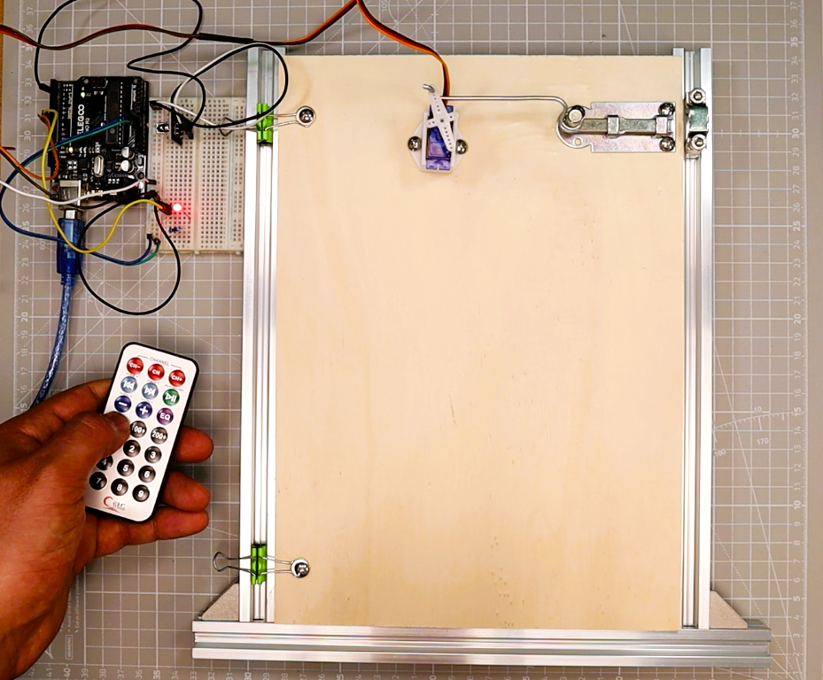
هل تريد التحكم في الأجهزة الحقيقية باستخدام جهاز تحكم عن بعد يشبه جهاز التلفزيون؟ في هذا البرنامج التعليمي عن بعد من Arduino IR، ستقوم ببناء وحدة تحكم LED لاسلكية باستخدام جهاز تحكم عن بعد بالأشعة تحت الحمراء ووحدة استقبال KY-022، ثم ترقية نفس الدائرة لتشغيل باب يعمل بمحرك مؤازر. تم تنظيم المشروع على مرحلتين تدريجيتين حتى تتمكن من التعلم بالسرعة التي تناسبك: أولاً مفتاح تبديل LED بسيط، ثم باب ميكانيكي يفتح ويغلق عند الطلب.
على وجه التحديد، يعتمد هذا البرنامج التعليمي على آلية الباب من موقعنا قفل باب بكلمة مرور من أردوينو مشروع. إذا قمت بالفعل ببناء مزلاج المؤازرة هذا، فيمكنك إعادة استخدامه هنا وتبديل التحكم في لوحة المفاتيح بجهاز التحكم عن بعد بالأشعة تحت الحمراء. إذا كنت جديدًا في مجال المحركات المؤازرة، فلدينا محرك سيرفو مع عصا التحكم وبرنامج تعليمي OLED هو دليل رفيق عظيم.
ما الذي ستبنيه
- وحدة تحكم LED فقط (الجزء 1): اضغط على زر واحد عن بعد لتبديل مؤشر LED الموجود على الدبوس D8. وهذا يعلم فك تشفير الأشعة تحت الحمراء، وتكرار التصفية، والإخراج الرقمي الأساسي.
- ترقية الباب LED + المؤازر (الجزء 2): أضف زرين آخرين عن بعد لفتح وإغلاق باب مؤازر صغير على الدبوس D9. يعكس مؤشر LED حالة الباب تلقائيًا (تشغيل عند فتحه، وإيقاف تشغيله عند إغلاقه).
كيف يعمل النظام
على وجه الخصوص، يساعدك فهم سلسلة الإشارة على تصحيح المشكلات وتكييف المشروع وفقًا لاحتياجاتك الخاصة. إليك ما يحدث في كل مرة تضغط فيها على زر في جهاز التحكم عن بعد:
- جهاز التحكم عن بعد يرسل إشارة الأشعة تحت الحمراء. عندما تضغط على زر، يومض جهاز التحكم عن بعد بمصباح LED بالأشعة تحت الحمراء بموجة حاملة معدلة 38 كيلو هرتز. يرسل كل زر رمزًا فريدًا محددًا بواسطة بروتوكول NEC (أو ما شابه).
- بعد ذلك، يقوم جهاز الاستقبال KY-022 بإزالة تشكيل الإشارة. تقوم وحدة استقبال الأشعة تحت الحمراء بإزالة الموجة الحاملة 38 كيلو هرتز وتخرج قطارًا نبضيًا رقميًا نظيفًا على طرف OUT الخاص بها، والذي يتصل بمنفذ Arduino D2.
- تقوم مكتبة IRremote بفك تشفير الإطار. تلتقط مقاطعة المكتبة توقيت النبض، وتحدد البروتوكول، وتكشف ما تم فك تشفيره
يأمربايت والكاملالبيانات الخام التي تم فك تشفيرهاكلمة. كما يقوم أيضًا بوضع علامات على الإطارات المتكررة التي يرسلها جهاز التحكم عن بعد أثناء الضغط باستمرار على الزر. - يعمل Arduino بناءً على الأمر الذي تم فك تشفيره. يقارن الرسم الخاص بك الأمر المستلم بالقيم المخزنة. في تصميم LED فقط، تعمل المباراة على تبديل مؤشر LED. في ترقية المؤازرة، يقوم أمرا OPEN وCLOSE بنقل المؤازرة إلى الزاوية المستهدفة بينما يتبع مؤشر LED حالة الباب.
نظرًا لأن البنية متطابقة في كلتا المرحلتين، فإن الترقية من LED فقط إلى LED + مؤازرة هي ببساطة مسألة إضافة أسلاك وتعيين زرين إضافيين عن بعد.
المكونات المطلوبة
باختصار، يسرد الجدول أدناه كل جزء تحتاجه. المكونات التي تم وضع علامة اختيار عليها في عمود LED فقط تكفي للجزء 1. أضف الأجزاء المتبقية عندما تكون جاهزًا لترقية باب المؤازرة في الجزء 2.
| عنصر | مصابيح LED فقط (الجزء الأول) | ترقية المؤازرة (الجزء الثاني) | ملحوظات |
|---|---|---|---|
| أردوينو أونو (أو نانو) | نعم | نعم | تعمل أي لوحة تعتمد على ATmega328 |
| وحدة استقبال الأشعة تحت الحمراء (KY-022 / VS1838B / TSOP1838) | نعم | نعم | وحدة 3 دبوس؛ OUT يذهب إلى D2 |
| جهاز التحكم عن بعد بالأشعة تحت الحمراء (جهاز التحكم عن بعد) | نعم | نعم | تعمل معظم أجهزة التحكم عن بعد الخاصة ببروتوكول NEC |
| مصباح LED (أي لون) | نعم | نعم | فتحة قياسية بقطر 5 مم |
| مقاومة 220 اوم | نعم | نعم | مقاومة تحديد التيار للثنائي الباعث للضوء (LED) |
| لوحة تجارب وأسلاك توصيل | نعم | نعم | نصف حجم اللوح يكفي |
| أجهزة مايكرو (SG90 أو MG90S) | No | نعم | SG90 للأبواب خفيفة الوزن |
| مصدر طاقة خارجي 5 فولت (1 أمبير أو أكثر) | No | نعم | يمنع براونوتس. لا تقم بتشغيل المؤازرة من Arduino 5 V |
| مزلاج الباب أو الآلية | No | نعم | الطباعة ثلاثية الأبعاد أو الأسلاك أو الورق المقوى |
نصيحة ذهبية: ترسم المحركات المؤازرة طفرات تيار كبيرة عندما تبدأ في التحرك. الأهم من ذلك، قم دائمًا بتشغيل المؤازرة من مصدر منفصل بجهد 5 فولت وقم بتوصيل GND للإمداد بـ Arduino GND (أرضية مشتركة). بدون هذا الاتصال، سوف تواجه عمليات إعادة تعيين، وعدم استقرار، واستقبال غير موثوق للأشعة تحت الحمراء.
الجزء 1 - Arduino IR Remote LED (إصدار LED فقط)
مخطط الدائرة - أسلاك LED فقط
لبناء الدائرة، قم بتوصيل مستقبل الأشعة تحت الحمراء وLED إلى Arduino كما هو موضح في الجدول والرسم البياني أدناه. يتصل دبوس OUT لجهاز استقبال IR بـ D2 (مكتبة IRremote الافتراضية). يتصل أنود LED عبر مقاومة 220 أوم بـ D8.
| عنصر | دبوس / المحطة | يتصل بـ |
|---|---|---|
| جهاز استقبال الأشعة تحت الحمراء (KY-022) | خارج (ق) | اردوينو D2 |
| جهاز استقبال الأشعة تحت الحمراء (KY-022) | سي سي (+) | أردوينو 5 فولت |
| جهاز استقبال الأشعة تحت الحمراء (KY-022) | الارض (-) | أرضي أردوينو |
| الأنود LED (الساق الطويلة) | الأنود (+) | مقاومة 220 أوم ثم إلى Arduino D8 |
| كاثود LED (ساق قصيرة) | الكاثود (-) | أرضي أردوينو |
على وجه الخصوص، لاحظ نصيحة المبتدئين هذه – قطبية LED: الجزء الأطول من LED هو الأنود (إيجابي). الساق الأقصر هي الكاثود (سلبي، وغالبًا ما يتم تمييزه بحافة مسطحة على جسم LED). يمكن أن يستمر المقاوم 220 أوم على جانبي LED؛ فهو يحد من التيار لحماية LED ودبوس Arduino. إذا لم يضيء مؤشر LED، فحاول قلبه.
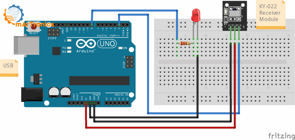
مخطط توصيلات LED فقط: جهاز استقبال IR KY-022 متصل بـ D2، LED بمقاومة 220 أوم متصلة بـ D8 على Arduino Uno.
الخطوة 1 - تثبيت مكتبة IRremote
أولاً، افتح Arduino IDE وانتقل إلى الأدوات > إدارة المكتبات. بحث عن جهاز تحكم عن بعد بالأشعة تحت الحمراء بواسطة Arduino-IRremote وقم بتثبيت أحدث إصدار. يستخدم هذا البرنامج التعليمي واجهة برمجة التطبيقات IRremote 3.x+ الحديثة مع IRremote.hpp و اير ريسيفر.بدء ().
تتعامل المكتبة مع جميع التوقيتات ذات المستوى المنخفض واكتشاف البروتوكول. بعد التثبيت يمكنك تضمينه وتهيئة جهاز الاستقبال بخطين:
#include // ... IrReceiver.begin(pin, ENABLE_LED_FEEDBACK);
لمزيد من المرجع، مستودع IRremote GitHub الرسمي يحتوي على وثائق كاملة إذا كنت ترغب في استكشاف الميزات المتقدمة.
الخطوة 2 - مسح جهاز التحكم عن بعد (ماسح رمز الأشعة تحت الحمراء)
يرسل كل جهاز تحكم عن بعد رموزًا مختلفة، حتى لو كانت تبدو متطابقة. لذلك، قبل كتابة الرسم النهائي، يجب عليك مسح جهاز التحكم عن بعد الخاص بك لمعرفة الرمز الذي يرسله كل زر. هذه الخطوة ضرورية لأن قيم المثال في الكود النهائي (0x45, 0x46، وما إلى ذلك) من المؤكد تقريبًا أنها لا تتطابق مع جهاز التحكم عن بعد الخاص بك.
قم بتحميل رسم الماسح الضوئي أدناه، ثم افتحه مراقب تسلسلي عند 115200 باود، واضغط على كل زر بعيد عدة مرات. نحن نستخدم 115200 باود (بدلاً من 9600 الشائع) لأن مكتبة IRremote تطبع مخرجات مفصلة تستفيد من السرعة الأعلى.
// IR Code Scanner (IRremote >= 3.x)
#include <IRremote.hpp>
const uint8_t IR_RECEIVE_PIN = 2;
void setup(){
  Serial.begin(115200);
  IrReceiver.begin(IR_RECEIVE_PIN, ENABLE_LED_FEEDBACK);
  Serial.println(F("IR Scanner ready. Press remote buttons..."));
}
void loop(){
  if(IrReceiver.decode()){
    IrReceiver.printIRResultShort(&Serial); // concise one-liner
    Serial.print(F("Protocol="));   Serial.print(IrReceiver.decodedIRData.protocol);
    Serial.print(F("  Command=0x"));Serial.print(IrReceiver.decodedIRData.command, HEX);
    Serial.print(F("  RAW=0x"));    Serial.println(IrReceiver.decodedIRData.decodedRawData, HEX);
    IrReceiver.resume();
  }
}
ما الذي تبحث عنه: كل ضغطة زر تطبع أ يأمر القيمة و أ خام قيمة. مع معظم أجهزة التحكم عن بعد لمجموعة بروتوكولات NEC، فإن يأمر البايت قصير ومستقر عبر المطابع. اكتبها. إذا لاحظت ذلك يأمر يتغير بشكل عشوائي أو يظهر 0x00، استخدم الإصدار 32 بت الكامل البيانات الخام التي تم فك تشفيرها (RAW) بدلاً من ذلك. تتوفر قيمة RAW دائمًا كقيمة احتياطية بغض النظر عن البروتوكول.
اختر زرًا واحدًا لتبديل LED. بالإضافة إلى ذلك، إذا كنت تخطط لإجراء ترقية المؤازرة، فاختر أيضًا أزرارًا منفصلة للفتح والإغلاق. وأخيرًا، قم بتدوين القيم الثلاث قبل المتابعة.
الخطوة 3 - رمز LED عن بعد لـ Arduino IR (الرسم النهائي لـ LED فقط)
التالي، استبدال CMD_LED_TOGGLE بقيمة الأمر التي وجدتها في الماسح الضوئي. إذا كان بايت أمر جهاز التحكم عن بعد الخاص بك غير موثوق به، فقم بإلغاء التعليق على سطر RAW واستخدمه RAW_LED_TOGGLE بدلاً من.
// IR Code Scanner (IRremote >= 3.x)
#include <IRremote.hpp>
const uint8_t IR_RECEIVE_PIN = 2; // IR OUT → D2
const uint8_t LED_PIN        = 8; // LED → 220Ω → D8
// Replace with your scanned value:
const uint32_t CMD_LED_TOGGLE = 0x45;  // example NEC command
// Alternative if command is unstable:
// const uint32_t RAW_LED_TOGGLE = 0x00FFA25D; // example 32-bit RAW
bool ledOn = false;
void setLED(bool on){
  ledOn = on;
  digitalWrite(LED_PIN, ledOn ? HIGH : LOW);
}
void setup(){
  pinMode(LED_PIN, OUTPUT);
  setLED(false);
  Serial.begin(115200);
  IrReceiver.begin(IR_RECEIVE_PIN, ENABLE_LED_FEEDBACK);
  Serial.println(F("LED-only mode. Press your toggle key."));
}
void loop(){
  if(!IrReceiver.decode()) return;
  if(!(IrReceiver.decodedIRData.flags & IRDATA_FLAGS_IS_REPEAT)){
    uint32_t cmd = IrReceiver.decodedIRData.command;
    uint32_t raw = IrReceiver.decodedIRData.decodedRawData;
    if (cmd == CMD_LED_TOGGLE)        setLED(!ledOn);
    // else if (raw == RAW_LED_TOGGLE) setLED(!ledOn); // use if needed
    Serial.print(F("[IR] cmd=0x")); Serial.print(cmd, HEX);
    Serial.print(F(" raw=0x"));     Serial.println(raw, HEX);
  }
  IrReceiver.resume();
}
كيف يعمل رمز LED فقط
فيما يلي تفصيل للأجزاء الرئيسية من المخطط حتى تتمكن من فهم ما يفعله كل قسم ويمكنك تعديله بثقة:
- IRDATA_FLAGS_IS_REPEAT: عند الضغط باستمرار على زر على جهاز التحكم عن بعد الذي يعمل بالأشعة تحت الحمراء، يرسل جهاز التحكم عن بعد باستمرار إطارات متكررة على فترات زمنية قصيرة. بدون التصفية، يمكن لضغطة واحدة طويلة أن تقوم بتبديل مؤشر LED عدة مرات. الخط
إذا (!(IrReceiver.decodedIRData.flags & IRDATA_FLAGS_IS_REPEAT))يتجاهل هذه الإطارات المتكررة لذا يتم احتساب الضغطة الأولى فقط. - الأمر مقابل decodedRawData: ال
يأمريحتوي الحقل على رمز الزر القصير الخاص بالبروتوكول (عادةً 1 بايت لـ NEC). الالبيانات الخام التي تم فك تشفيرهايحتوي الحقل على الإطار الخام الكامل 32 بت بما في ذلك العنوان والأمر. يستخدميأمرعندما يكون مستقرًا لجهاز التحكم عن بعد الخاص بك. العودة إلىالبيانات الخام التي تم فك تشفيرهالويأمرإرجاع قيم غير متناسقة أو صفر. - وظيفة المساعد setLED(): مركزية منطق LED في
مجموعة LED ()يعني أن كل جزء من البرنامج يغير LED بنفس الطريقة. وهذا مهم أكثر في ترقية المؤازرة حيث يجب أن يعكس مؤشر LED حالة الباب. عن طريق الاتصالمجموعة LED ()في كل مكان بدلا منdigitalWrite()directly, you avoid bugs where the LED and the internal state variable get out of sync. - استبدال قيمة المثال: القيمة
0x45هو مجرد مثال. افتح رسم الماسح الضوئي من الخطوة 2، واضغط على الزر الذي تريد استخدامه، ثم استبدله0x45معيأمرالقيمة السداسية الموضحة في جهاز العرض التسلسلي. إذا كنت بحاجة إلى النسخة الاحتياطية من RAW، فقم بإلغاء التعليق على سطر RAW واستبدله0x00FFA25Dبقيمة RAW الممسوحة ضوئيًا.
الجزء 2 - الترقية إلى Arduino IR Remote LED + Servo Door
الآن قم بتوسيع البنية: على وجه التحديد، احتفظ بكل منطق LED من الجزء 1، وأضف محركًا مؤازرًا، وقم بتعيين مفتاحين بعيدين آخرين (فتح وإغلاق). سيظهر مؤشر LED حالة الباب تلقائيًا: تشغيل يعني أن الباب مفتوح، وإيقاف يعني أنه مغلق.
الأسلاك المؤازرة (إضافة إلى دائرة LED فقط)
أولاً، احتفظ بجميع أسلاك جهاز استقبال الأشعة تحت الحمراء وأسلاك LED من الجزء 1. ثم قم بإضافة التوصيلات المؤازرة المدرجة في الجدول أدناه.
| عنصر | دبوس / سلك | يتصل بـ |
|---|---|---|
| سيرفو (SG90) | إشارة (برتقالي/أصفر) | اردوينو D9 (PWM) |
| سيرفو (SG90) | VCC (أحمر) | مصدر خارجي 5 فولت (+) |
| سيرفو (SG90) | GND (بني/أسود) | مصدر خارجي 5 فولت (-) |
| العرض الخارجي GND | أرضي | اردوينو GND (أرضية مشتركة) |
لماذا نستخدم مصدر خارجي 5 فولت؟ الأهم من ذلك، أن منظم الجهد 5 فولت الموجود على لوحة Arduino يمكنه توفير حوالي 500 مللي أمبير فقط. يسحب محرك سيرفو 200-700 مللي أمبير في التشغيل العادي وحتى أعلى أثناء التوقف. يؤدي سحب هذا القدر الكبير من التيار عبر Arduino إلى انخفاض الجهد الذي يؤدي إلى إعادة ضبط اللوحة وإفساد استقبال الأشعة تحت الحمراء وإثارة ارتعاش المؤازرة. يتجنب مصدر إمداد منفصل 5 فولت 1 أمبير (أو أعلى) كل هذه المشكلات.
لماذا هناك حاجة إلى أرضية مشتركة: علاوة على ذلك، يجب أن يتشارك الاردوينو والإمداد الخارجي في اتصال أرضي. بدونه، لن يكون لسلك إشارة المؤازرة جهد مرجعي ولن يستجيب المؤازرة أو سيتصرف بشكل متقطع.
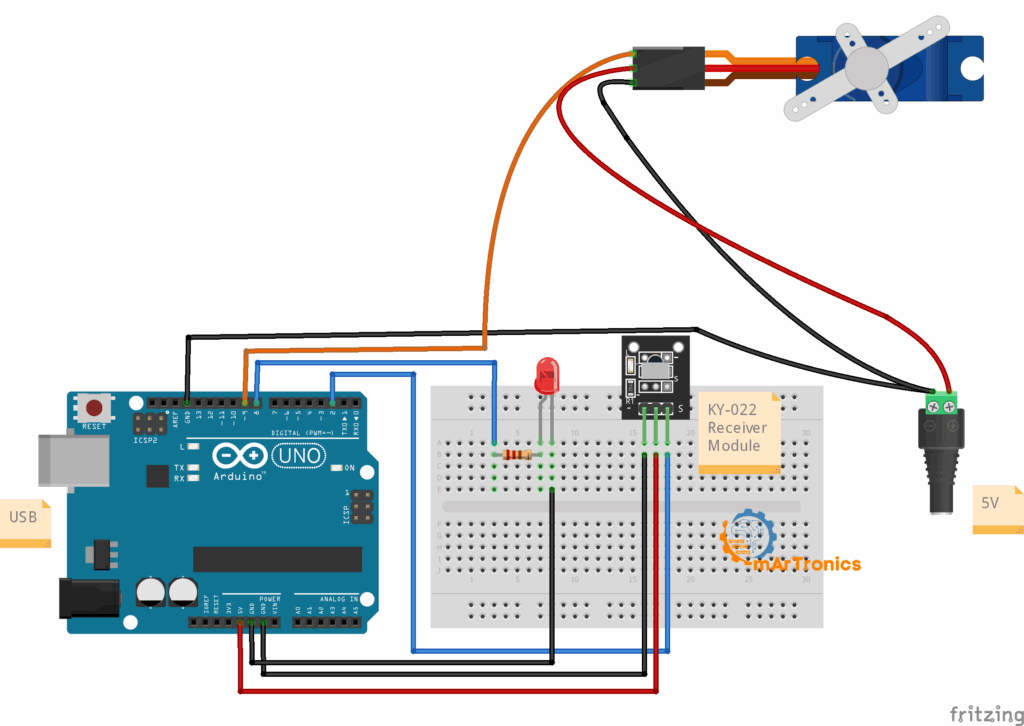
مخطط الأسلاك الكامل لترقية باب LED + المؤازر: KY-022 على D2، LED على D8، SG90 servo على D9 مدعوم بمصدر خارجي 5 فولت مع أرضية مشتركة لـ Arduino.
الكود المشترك — LED + باب مؤازر
قبل التحميل، استبدل CMD_LED_TOGGLE, CMD_OPEN, ، و CMD_CLOSE بالقيم الثلاث التي سجلتها في خطوة الماسح الضوئي. إذا كان جهاز التحكم عن بعد الخاص بك يحتاج إلى نسخة RAW الاحتياطية، فقم بإلغاء تعليق تلك السطور واملأ القيم الخاصة بك.
رسم مشترك كامل
// Arduino IR remote LED + Servo Door (IRremote >= 3.x)
#include <IRremote.hpp>
#include <Servo.h>
const uint8_t IR_RECEIVE_PIN = 2;   // IR OUT → D2
const uint8_t LED_PIN        = 8;   // LED → 220Ω → D8
const uint8_t SERVO_PIN      = 9;   // Servo signal → D9
// === Replace with your scanned values ===
const uint32_t CMD_LED_TOGGLE = 0x45; // LED toggle
const uint32_t CMD_OPEN       = 0x46; // door open
const uint32_t CMD_CLOSE      = 0x47; // door close
// RAW fallback (uncomment if needed):
// const uint32_t RAW_LED_TOGGLE = 0x00FFA25D;
// const uint32_t RAW_OPEN       = 0x00FF629D;
// const uint32_t RAW_CLOSE      = 0x00FF22DD;
const int OPEN_ANGLE  = 20;  // tune to your linkage
const int CLOSE_ANGLE = 90;
const int STEP_DEG    = 2;
const int STEP_MS     = 10;
Servo door;
bool ledOn = false;
int  curAngle = CLOSE_ANGLE;
void setLED(bool on){
  ledOn = on;
  digitalWrite(LED_PIN, on ? HIGH : LOW);
}
void moveServoTo(int target){
  int dir = (target > curAngle) ? 1 : -1;
  while(curAngle != target){
    curAngle += dir * STEP_DEG;
    if((dir > 0 && curAngle > target) || (dir < 0 && curAngle < target)) curAngle = target;
    door.write(curAngle);
    delay(STEP_MS);
  }
}
void setDoorOpen(bool open){
  moveServoTo(open ? OPEN_ANGLE : CLOSE_ANGLE);
  setLED(open); // LED shows door status: ON=open, OFF=closed
}
void setup(){
  Serial.begin(115200);
  pinMode(LED_PIN, OUTPUT);
  setLED(false);
  door.attach(SERVO_PIN);
  door.write(CLOSE_ANGLE);
  IrReceiver.begin(IR_RECEIVE_PIN, ENABLE_LED_FEEDBACK);
  Serial.println(F("LED + Servo mode. Use TOGGLE / OPEN / CLOSE keys."));
}
void loop(){
  if(!IrReceiver.decode()) return;
  if(!(IrReceiver.decodedIRData.flags & IRDATA_FLAGS_IS_REPEAT)){
    uint32_t cmd = IrReceiver.decodedIRData.command;
    uint32_t raw = IrReceiver.decodedIRData.decodedRawData;
    if (cmd == CMD_LED_TOGGLE) setLED(!ledOn);
    else if (cmd == CMD_OPEN)  setDoorOpen(true);
    else if (cmd == CMD_CLOSE) setDoorOpen(false);
    // RAW fallback:
    // if (raw == RAW_LED_TOGGLE) setLED(!ledOn);
    // if (raw == RAW_OPEN)       setDoorOpen(true);
    // if (raw == RAW_CLOSE)      setDoorOpen(false);
  }
  IrReceiver.resume();
}
كيف يعمل رمز الباب المؤازر
بشكل عام، يضيف الرسم المدمج ثلاث ميزات مهمة أعلى إصدار LED فقط. يعالج كل واحد تحديًا محددًا يتمثل في تحريك آلية مادية بشكل موثوق:
- OPEN_ANGLE وCLOSE_ANGLE: تحدد هذه الثوابت مدى دوران المؤازرة في الوضعين المفتوح والمغلق. القيم الافتراضية (20 و90 درجة) هي نقاط البداية. يجب عليك ضبطها لتتناسب مع رابط الباب الخاص بك. اختبر مع فصل المؤازرة أولاً، ثم قم بتوصيل البوق واضبطه حتى يفتح المزلاج بالكامل ويغلق بالكامل.
- حركة الخطوات الصغيرة (moveServoTo): بدلاً من القفز مباشرة إلى زاوية الهدف، يتحرك المؤازر بزيادات قدرها درجتين مع تأخير قدره 10 مللي ثانية بين الخطوات. تعمل هذه الحركة التدريجية على تقليل الضغط الميكانيكي على التروس المؤازرة، مما يقلل من ارتفاع التيار، ويجعل حركة الباب أكثر هدوءًا وسلاسة. يمكنك زيادة
الخطوة_أنتلحركة أسرع أو تقليلها لحركة أكثر سلاسة. - حالة باب المرايا LED: ال
سيت دوروبين ()استدعاءات الوظائفمجموعة LED ()بعد تحريك المؤازرة، يكون مؤشر LED دائمًا متزامنًا مع موضع الباب. ON يعني أن الباب مفتوح، و OFF يعني أنه مغلق. لا يزال بإمكانك تبديل مؤشر LED بشكل مستقل باستخدام زر تبديل LED إذا كنت تريد ذلك.
كيفية اختبار وضبط البناء
To verify everything works correctly, follow this step-by-step sequence to bring up the project safely and avoid frustration:
تسلسل الاختبار خطوة بخطوة
- اختبر الماسح الضوئي أولاً. قم بتحميل رسم الماسح الضوئي من الخطوة 2. افتح Serial Monitor على الرقم 115200. اضغط على كل زر بعيد وتأكد من أنك ترى مخرجات متسقة. إذا لم يظهر أي شيء، فافحص الأسلاك وتأكد من أن مخرج جهاز استقبال الأشعة تحت الحمراء يذهب إلى D2.
- التحقق من وظيفة LED فقط. قم بتحميل رسم LED فقط من الخطوة 3. اضغط على زر التبديل الذي اخترته. يجب أن يتم تشغيل مؤشر LED الموجود على D8 بالضغطة الأولى وينطفئ بالضغطة الثانية. شاهد Serial Monitor لقيم الأوامر التي تم فك تشفيرها للتأكد من مطابقتها لتوقعاتك.
- اختبر المؤازرة بدون آلية الباب. قبل توصيل المؤازرة بأي باب أو مزلاج، قم بتحميل الرسم المدمج واختبره مع إبقاء المؤازرة مفككة على المكتب. اضغط على فتح وإغلاق وتأكد من أن المؤازرة تدور بسلاسة بين الزاويتين. وهذا يمنع التروس المجردة إذا كانت الزوايا خاطئة.
- ضبط الزوايا المفتوحة والمغلقة. يُعدِّل
OPEN_ANGLEوCLOSE_ANGLEفي الكود حتى يصل ذراع المؤازرة إلى المواضع الصحيحة للمزلاج. أعد التحميل والاختبار بعد كل تغيير. تعتبر التغييرات الصغيرة بمقدار 5-10 درجات في المرة الواحدة أكثر أمانًا. - إرفاق الآلية والاختبار النهائي. قم بتركيب البوق المؤازر على مزلاج الباب الخاص بك. قم بتشغيل الرسم المدمج وتأكد من أن الباب يفتح ويغلق وأن مؤشر LED يعكس الحالة بشكل صحيح.
استكشاف الأخطاء وإصلاحها
إذا كان هناك شيء لا يعمل، فتحقق من هذه المشكلات الشائعة:
| مشكلة | السبب المحتمل | حل |
|---|---|---|
| لا يظهر أي إخراج تسلسلي | معدل باود خاطئ أو خطأ في الأسلاك | اضبط جهاز المراقبة التسلسلية على 115200. تأكد من أن جهاز استقبال IR متصل بـ D2 وأن الوحدة تحتوي على 5 فولت وGND. |
| الزر البعيد لا يعمل بشكل موثوق | إشارة ضعيفة أو المسافة أو الزاوية | قم بتوجيه الريموت مباشرة نحو جهاز الاستقبال من مسافة 3 أمتار. قم بإزالة مصادر الأشعة تحت الحمراء الساطعة (ضوء الشمس، وبعض المصابيح) التي يمكن أن تزيد من التحميل على جهاز الاستقبال. |
| تتغير قيمة الأمر بشكل غير متوقع | عدم تطابق البروتوكول أو الإشارة المزعجة | استخدم الخام (البيانات الخام التي تم فك تشفيرها) احتياطي بدلا من يأمر. تستخدم بعض أجهزة التحكم عن بعد بروتوكولات حيث يختلف بايت الأمر. |
| لا تبديل الصمام | قيمة الأمر خاطئة في التعليمات البرمجية | افتح رسم الماسح الضوئي، واضغط على الزر، وقارن القيمة السداسية بما لديك في رسم LED فقط. تحقق أيضًا من قطبية LED (اقلبها إذا لزم الأمر). |
| تؤدي الضغطات الطويلة إلى التبديل المتكرر | كرر التصفية المفقودة أو لا تعمل | تأكد من IRDATA_FLAGS_IS_REPEAT الاختيار موجود في الحلقة الخاصة بك. لا تقم بإزالة علامة الاختيار. |
| التوتر المؤازرة أو الطنين | طاقة غير كافية أو إشارة صاخبة | قم بتشغيل المؤازرة من مصدر خارجي بجهد 5 فولت مع أرضية مشتركة. تأكد من أن سلك الإشارة قصير وليس بالقرب من كابلات الطاقة. |
| المؤازرة لا تتحرك على الإطلاق | دبوس خاطئ، لا توجد طاقة، أو أمر خاطئ | تحقق من أن سلك الإشارة موجود على D9. تأكد من تشغيل مصدر الإمداد الخارجي وأن GND متصل بـ Arduino GND. تحقق من تطابق قيم الأمر OPEN وCLOSE مع مخرجات الماسح الضوئي لديك. |
| يتحرك المؤازرة في الاتجاه الخاطئ | تم تبديل OPEN_ANGLE وCLOSE_ANGLE | مبادلة قيم OPEN_ANGLE و CLOSE_ANGLE في الكود ثم إعادة التحميل |
| يتم إعادة تعيين اردوينو عندما يتحرك المؤازرة | يسحب المؤازرة الكثير من التيار من Arduino | هذه هي المشكلة الأكثر شيوعا. استخدم مصدرًا خارجيًا بجهد 5 فولت للمؤازرة. لا يستطيع طرف Arduino 5 V التعامل مع طفرات التيار المؤازرة. |
| يتوقف IR عن العمل بعد إضافة السيرفو | ضجيج مصدر الطاقة أو تعارض الموقت | أضف مكثف 100 فائق التوهج عبر خطوط الطاقة المؤازرة. تأكد من أن IRremote يستخدم Timer 2 (الإعداد الافتراضي في Uno) وأن Servo يستخدم Timer 1. |
الأسئلة الشائعة
ما هي وحدة استقبال الأشعة تحت الحمراء KY-022؟
KY-022 عبارة عن لوحة فرعية صغيرة تحمل جهاز استقبال الأشعة تحت الحمراء VS1838B أو TSOP1838. فهو يزيل إشارات الأشعة تحت الحمراء بتردد 38 كيلو هرتز ويخرج إشارة رقمية نظيفة يمكن لاردوينو قراءتها. تعرض الوحدة ثلاثة منافذ: الإشارة (OUT)، وVCC، وGND. ونتيجة لذلك، فهي واحدة من وحدات استقبال الأشعة تحت الحمراء الأكثر شيوعًا في مجموعات Arduino المبتدئة.
ما هي منافذ Arduino التي يستخدمها مستقبل الأشعة تحت الحمراء؟
في هذا البرنامج التعليمي، يتصل طرف OUT لجهاز استقبال الأشعة تحت الحمراء بالدبوس الرقمي D2. تستخدم مكتبة IRremote مقاطعة جهاز ضبط الوقت، وليس دبوسًا محددًا، لذا يمكنك تغيير دبوس الاستلام إذا لزم الأمر. ومع ذلك، D2 هو الإعداد الافتراضي التقليدي لمعظم أمثلة IRremote.
هل يمكنني استخدام جهاز تحكم عن بعد يعمل بالأشعة تحت الحمراء بدلاً من جهاز التحكم عن بعد الخاص بالمجموعة؟
نعم. سيعمل أي جهاز تحكم عن بعد يعمل بالأشعة تحت الحمراء يستخدم موجة حاملة 38 كيلو هرتز مع جهاز الاستقبال KY-022. تعمل جميع أجهزة التحكم عن بعد الخاصة بالتلفزيون وأجهزة التحكم عن بعد الخاصة بمكيفات الهواء وأجهزة التحكم عن بعد العامة. ما عليك سوى تشغيل رسم الماسح الضوئي للعثور على رموز الأزرار لجهاز التحكم عن بُعد الخاص بك.
ما الفرق بين الأمر وdecodedRawData في مكتبة IRremote؟
ال يأمر يحتوي الحقل على رمز الزر الذي تم فك تشفيره بواسطة البروتوكول، وعادة ما يكون بايت واحد لأجهزة التحكم عن بعد الخاصة بشركة NEC. ال البيانات الخام التي تم فك تشفيرها يحتوي الحقل على الإطار الخام الكامل 32 بت بما في ذلك بتات العنوان. يستخدم يأمر عندما يعطي نتائج مستقرة. يستخدم البيانات الخام التي تم فك تشفيرها كاحتياطي إذا يأمر يُرجع صفرًا أو يختلف بين المطابع.
لماذا يتم تبديل مؤشر LED الخاص بي مرتين بضغطة زر واحدة؟
يعني هذا عادةً أن مرشح إطار التكرار مفقود أو لا يعمل بشكل صحيح. تأكد من أن الحلقة الخاصة بك تتضمن IRDATA_FLAGS_IS_REPEAT يفحص. تأكد أيضًا من أنك تستخدم الإصدار 3.x من IRremote أو إصدار أحدث، حيث تغيرت واجهة برمجة التطبيقات (API) بشكل ملحوظ عن الإصدار 2.x.
هل يمكنني التحكم في أكثر من LED باستخدام جهاز التحكم عن بعد الذي يعمل بالأشعة تحت الحمراء؟
نعم. قم بمسح الأزرار الإضافية ضوئيًا باستخدام رسم الماسح الضوئي، وقم بتعيين كل منها إلى دبوس مختلف، وأضف المزيد لو الظروف في الحلقة. تتدرج البنية الموجودة في هذا البرنامج التعليمي بسهولة إلى مخرجات متعددة.
هل أحتاج إلى مصدر طاقة خارجي لبناء LED فقط؟
لا، فتصميم LED فقط يستهلك تيارًا قليلًا للغاية ويعمل بشكل جيد من طاقة USB وحدها. ومع ذلك، من أجل ترقية محرك سيرفو في الجزء 2، يلزم توفر مصدر خارجي بجهد 5 فولت.
لماذا يهتز المؤازرة عندما لا يتحرك؟
بشكل عام، يكون اهتزاز المؤازرة دائمًا مشكلة في الطاقة. إذا كان المؤازرة تشترك في سكة Arduino 5 V، فإن تقلبات الجهد تتسبب في ارتعاش المؤازرة. استخدم مصدرًا خارجيًا مخصصًا بقدرة 5 فولت مع أرضية مشتركة. تساعد أيضًا إضافة مكثف إلكتروليتي 100 فائق التوهج عبر قضبان الطاقة المؤازرة.
هل يمكنني استخدام جهاز التحكم عن بعد بالأشعة تحت الحمراء هذا لأتمتة المنزل؟
في الواقع، يعد هذا المشروع نقطة انطلاق رائعة لأتمتة المنزل البسيطة القائمة على الأشعة تحت الحمراء. يمكنك إضافة مرحلات للتحكم في الأضواء أو المراوح أو الأجهزة الأخرى. للحصول على مشروع أكثر تقدمًا للتحكم في الباب، راجع موقعنا قفل باب بكلمة مرور من أردوينو برنامج تعليمي يضيف مصادقة لوحة المفاتيح إلى آلية الباب المؤازرة نفسها.
ماذا علي أن أفعل إذا تعارضت مكتبة IRremote مع مكتبة Servo؟
على وجه الخصوص، في Arduino Uno، تستخدم مكتبة IRremote Timer 2 وتستخدم مكتبة Servo Timer 1، لذلك لا تتعارضان بشكل افتراضي. إذا كنت تستخدم لوحة مختلفة أو إصدارًا مختلفًا من مكتبة IR، فتحقق من تعيينات المؤقت في وثائق المكتبة. في اللوحات التي تحتوي على مؤقتات أقل، قد تحتاج إلى استخدام مكتبة مؤازرة برمجية بدلاً من ذلك.
التنزيلات والموارد
رمز من هذا البرنامج التعليمي
- رسم الماسح الضوئي - استخدم الماسح الضوئي لرمز الأشعة تحت الحمراء في الخطوة 2 أعلاه للعثور على رموز أزرار جهاز التحكم عن بعد.
- رسم LED فقط - يقوم رمز LED النهائي فقط في الخطوة 3 بتبديل مؤشر LED الموجود على D8 باستخدام زر بعيد واحد.
- مجتمعة LED + رسم المؤازرة - يتحكم الكود المدمج الكامل في الجزء 2 في كل من مؤشر LED وباب المؤازرة.
دروس تعليمية ذات صلة من OmArTronics
- قفل باب بكلمة مرور أردوينو مع لوحة مفاتيح وشاشة LCD - آلية الباب الأصلية التي يعتمد عليها هذا المشروع. يستخدم لوحة مفاتيح وشاشة LCD بدلاً من جهاز التحكم عن بعد بالأشعة تحت الحمراء.
- التحكم في محرك سيرفو باستخدام عصا التحكم وشاشة OLED - تعرف على المزيد حول التحكم المؤازر من خلال الإدخال التناظري والتعليقات المرئية.
- بناء خط يتبع الروبوت — مشروع الروبوتات الذي يجمع بين أجهزة الاستشعار والتحكم في المحركات.
الموارد الخارجية
المشاريع القادمة المقترحة
الآن بعد أن أصبح بإمكانك فك تشفير إشارات الأشعة تحت الحمراء والتحكم في المخرجات، إليك بعض الأفكار لتوسيع مهاراتك. على سبيل المثال، يمكنك:
- على سبيل المثال، أضف وحدة ترحيل للتحكم في مصباح أو مروحة تعمل بالتيار الكهربائي باستخدام نفس جهاز التحكم عن بعد الذي يعمل بالأشعة تحت الحمراء.
- بالإضافة إلى ذلك، أضف شاشة LCD أو شاشة OLED لعرض حالة الباب الحالية وآخر أمر تم استلامه.
- قم بدمج إدخال الأشعة تحت الحمراء عن بعد مع قفل باب لوحة المفاتيح لأمان المصادقة المزدوجة.
- وبدلاً من ذلك، قم بتسجيل أوامر IR على بطاقة SD لإنشاء سجل وصول بسيط لبابك.
خاتمة
في هذا البرنامج التعليمي عن بعد لـ Arduino IR، قمت ببناء نظام تحكم لاسلكي كامل على مرحلتين. أعطاك الجزء الأول مفتاح تبديل LED بسيط يتم التحكم فيه بواسطة جهاز تحكم عن بعد يعمل بالأشعة تحت الحمراء وجهاز استقبال KY-022، ويعلمك كيفية مسح رموز الأزرار، وتصفية الإطارات المتكررة، وفك تشفير إشارات الأشعة تحت الحمراء باستخدام مكتبة IRremote. قام الجزء الثاني بترقية نفس الدائرة بباب يعمل بمحرك مؤازر، حيث يعكس مؤشر LED تلقائيًا ما إذا كان الباب مفتوحًا أم مغلقًا.
ونتيجة لذلك، يعني هذا النهج المعياري أنه يمكنك إعادة استخدام نفس بنية التحكم عن بعد بالأشعة تحت الحمراء في أي مشروع يحتاج إلى إدخال زر لاسلكي. سواء أضفت المزيد من مصابيح LED أو المرحلات أو المحركات، فسيظل منطق المسح وفك التشفير كما هو.
أخيرًا، إذا كنت تريد أن تأخذ آلية الباب إلى أبعد من ذلك، فاطلع على قفل باب بكلمة مرور من أردوينو للأمان المعتمد على لوحة المفاتيح، أو استكشف موقعنا محرك سيرفو مع البرنامج التعليمي عصا التحكم لمزيد من الطرق للتحكم في حركة المؤازرة باستخدام Arduino.