
جدول المحتويات
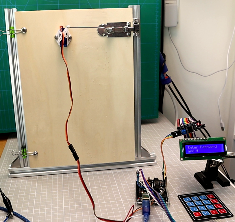
ToggleIn this tutorial, we will build an Arduino Password Door Lock using a 4×4 keypad, a 16×2 LCD with I2C module, and a small SG90 servo motor. This project demonstrates how to create a simple electronic lock where you enter a password on the keypad, and the servo unlocks or locks the door.
The Arduino Password Door Lock is a perfect beginner project because it teaches you:
How to connect a keypad and LCD display to Arduino.
How to write code for password handling.
How to control a servo motor for mechanical movement.
Components Required
To build this project, you need:
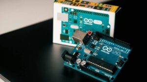
Arduino Uno (or compatible board)
4×4 Matrix Keypad (8 pins)
16×2 LCD Display with I2C adapter
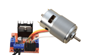
SG90 Servo motor
Jumper wires and breadboard
A small door lock or latch (for demo setup)
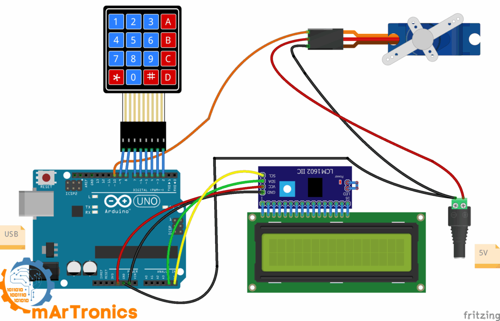
Circuit Diagram of Arduino Password Door Lock
The wiring is simple:
-
LCD I2C module → SDA to A4, SCL to A5, VCC to 5V, GND to GND.
-
Keypad rows → Arduino pins D9, D8, D7, D6.
-
Keypad columns → Arduino pins D5, D4, D3, D2.
-
Servo signal → D10, VCC to 5V, GND to GND.
! Tip: Use a separate 5V power supply for the servo motor if possible, because USB power is often not enough.
Arduino Code for Password Door Lock
-
Below is the full code. It allows you to:
-
Enter a password and press
#to unlock. -
Door remains open.
-
LCD shows: “Enter * to close”.
-
When you press
*, the servo closes the door again.
-
/**
Password Door Lock
 */

#include <Wire.h>
#include <LiquidCrystal_I2C.h>
#include <Keypad.h>
#include <Servo.h>

// LCD
#define LCD_ADDR 0x27
LiquidCrystal_I2C lcd(LCD_ADDR, 16, 2);

// Servo
#define SERVO_PIN 10
#define LOCK_ANGLE   0
#define UNLOCK_ANGLE 90
Servo lockServo;

// Keypad
const byte ROWS = 4;
const byte COLS = 4;
char keys[ROWS][COLS] = {
  {'1','2','3','A'},
  {'4','5','6','B'},
  {'7','8','9','C'},
  {'*','0','#','D'}
};
byte rowPins[ROWS] = {9, 8, 7, 6};
byte colPins[COLS] = {5, 4, 3, 2};
Keypad keypad = Keypad(makeKeymap(keys), rowPins, colPins, ROWS, COLS);

// Password
String PASSWORD = "1234";
String input = "";
bool doorUnlocked = false;

void lcdPromptLocked() {
  lcd.clear();
  lcd.setCursor(0,0);
  lcd.print("Enter Password");
  lcd.setCursor(0,1);
  lcd.print("and #");
}

void lcdPromptUnlocked() {
  lcd.clear();
  lcd.setCursor(0,0);
  lcd.print("Door is OPEN");
  lcd.setCursor(0,1);
  lcd.print("Enter * to close");
}

void lockDoor() {
  lockServo.write(LOCK_ANGLE);
  doorUnlocked = false;
  lcdPromptLocked();
  input = "";
}

void unlockDoor() {
  lockServo.write(UNLOCK_ANGLE);
  doorUnlocked = true;
  lcdPromptUnlocked();
  input = "";
}

void wrongPasswordMsg() {
  lcd.clear();
  lcd.setCursor(0,0);
  lcd.print("Wrong Password");
  lcd.setCursor(0,1);
  lcd.print("Try again");
  delay(1500);
  lcdPromptLocked();
  input = "";
}

void handleKey(char k) {
  if (doorUnlocked) {
    if (k == '*') lockDoor();
    return;
  }
  if (k == '#') {
    if (input == PASSWORD) unlockDoor();
    else wrongPasswordMsg();
  } else if (k == '*') {
    input = "";
    lcdPromptLocked();
  } else if (k == 'D') {
    if (input.length() > 0) input.remove(input.length()-1);
  } else {
    if (input.length() < 8) input += k;
  }
  lcd.setCursor(0,1);
  lcd.print(String(input.length(), '*'));
}

void setup() {
  lcd.init();
  lcd.backlight();
  lockServo.attach(SERVO_PIN);
  lockDoor();
}

void loop() {
  char key = keypad.getKey();
  if (key) handleKey(key);
}
Code Breakdown: How the Arduino Password Door Lock Works
1) Libraries and Objects
#include <Wire.h>
#include <LiquidCrystal_I2C.h>
#include <Keypad.h>
#include <Servo.h>

// LCD
#define LCD_ADDR 0x27
LiquidCrystal_I2C lcd(LCD_ADDR, 16, 2);

// Servo
#define SERVO_PIN 10
#define LOCK_ANGLE   0
#define UNLOCK_ANGLE 90
Servo lockServo;
-
Brings in the drivers for the I²C LCD, keypad scanning, and the servo.
-
Creates the lcd and lockServo objects used everywhere.
2) Hardware Configuration (Pins & Angles)
#define LCD_ADDR 0x27
#define SERVO_PIN 10
#define LOCK_ANGLE 0
#define UNLOCK_ANGLE 90
-
Sets the I²C address (change to
0x3Fif your module uses it). -
Chooses D10 for the servo signal.
-
Defines two angles for the mechanical lock positions.
3) Keypad Layout and Wiring
const byte ROWS = 4, COLS = 4;
char keys[ROWS][COLS] = { ... };
byte rowPins[ROWS] = {9, 8, 7, 6};
byte colPins[COLS] = {5, 4, 3, 2};
Keypad keypad = Keypad(makeKeymap(keys), rowPins, colPins, ROWS, COLS);
-
Describes the 4×4 keypad character map.
-
Maps the 4 row pins and 4 column pins to Arduino pins.
-
The
Keypadlibrary handles debouncing and key detection for yo
4) Password State and Variables
String PASSWORD = "1234";
String input = "";
bool doorUnlocked = false;
-
PASSWORDis the correct code (easy to change). -
inputstores what the user typed. -
doorUnlockedtracks whether the door is open or closed.
5) LCD Helper Screens
void lcdPromptLocked() { ... }     // "Enter Password" / "and #"
void lcdPromptUnlocked() { ... }   // "Door is OPEN" / "Enter * to close"
-
Shows clear instructions depending on the mode.
-
Keeps the user interface consistent and readable.
6) Door Control Helpers
void lockDoor() { ... }
void unlockDoor() { ... }
-
lockDoor(): moves the servo to
LOCK_ANGLE, resets state, shows the lock prompt. -
unlockDoor(): moves the servo to
UNLOCK_ANGLE, sets state to open, shows the “Enter * to close” prompt.
7) Feedback on Wrong Password
void wrongPasswordMsg() { ... }
-
Displays a short error message.
-
After a brief delay, it returns to the locked prompt and clears the input.
8) Central Input Logic (handleKey)
void handleKey(char k) { ... }
This is the brain of the Arduino Password Door Lock:
-
If door is open: only
*is accepted to close the door (safety and clarity). -
If door is locked:
-
#→ comparesinputwithPASSWORD. If they match, unlock; else show error. -
*→ clears the entireinput. -
D→ backspace (delete last character). -
Digits /
A B C→ append toinputuntil max length (8).
-
-
At the end, it masks the input on the LCD (shows
****instead of digits).
9) Setup: One-Time Initialization
void setup() {
  lcd.init(); lcd.backlight();
  lockServo.attach(SERVO_PIN);
  lockDoor();                      // start locked
  // optional welcome screen...
  lcdPromptLocked();
}
-
Starts the LCD, attaches the servo, and boots in locked mode.
-
Shows the first prompt: “Enter Password and #”.
10) Loop: Read Keys and React
void loop() {
  char key = keypad.getKey();
  if (key) handleKey(key);
}
-
Polls the keypad; if a key is pressed, it sends it to
handleKey. -
Because all logic is in
handleKey, theloop()stays simple and stable.
How the Arduino Password Door Lock Works
-
The LCD shows: “Enter Password and #”.
-
You type digits on the keypad.
-
When you press
#, the code checks the input. -
If the password is correct, the servo rotates to unlock the door.
-
LCD shows: “Door is OPEN – Enter * to close”.
-
-
The door stays open until you press
*. -
On pressing
*, the servo rotates back to the locked position.
Customize Your Arduino Password Door Lock
-
Change the password: set
PASSWORD = "6789";. -
Adjust mechanics: tune
LOCK_ANGLEandUNLOCK_ANGLEto match your latch. -
Improve power: use an external 5 V / ≥1 A supply for the servo; connect grounds.
-
Add features:
-
EEPROM to save a new password via a simple menu (e.g.,
Ato enter “change mode”). -
Buzzer on wrong attempts.
-
Relay for an electronic strike lock or magnetic door lock.
-
الخاتمة
The Arduino Password Door Lock is a fun and practical beginner project. With just a keypad, LCD, and servo motor, you can build your own electronic security system.
This project is perfect for learning keypad input, LCD display programming, and servo control with Arduino. With a few improvements, you can even turn it into a real home automation system.

Pingback: Arduino IR Remote LED: Then Add a Servo Door (DIY Guide)