
📋 ملخص سريع
قم ببناء نظام رادار Arduino كاملًا باستخدام مستشعر الموجات فوق الصوتية HC-SR04 المثبت على محرك سيرفو SG90، مع تصور المعالجة في الوقت الفعلي على جهاز الكمبيوتر الخاص بك. يقوم المؤازر بمسح المستشعر بمقدار 180 درجة بينما يتم إرسال بيانات المسافة عبر المسلسل لإنشاء شاشة على شكل رادار. يتضمن ملف تركيب STL، ورمز Arduino، ورسم المعالجة، ونصائح المعايرة.
في هذا البرنامج التعليمي لرادار Arduino، ستقوم ببناء رادار بالموجات فوق الصوتية يكتشف الأشياء القريبة ويظهرها على الشاشة. يستخدم الإعداد أردوينو أونو، وجهاز استشعار المسافة بالموجات فوق الصوتية HC-SR04، ومحرك سيرفو. يقوم جهاز مؤازر بمسح المستشعر عبر 180 درجة بينما يقوم Arduino بقياس المسافة إلى الأشياء في كل زاوية. يتم إرسال كل هذه البيانات عبر المسلسل إلى جهاز الكمبيوتر الخاص بك، وإذا كنت تريد، يمكن لرسم المعالجة أن يحولها إلى شاشة رادار حية.
يعجبني هذا المشروع لأنه يجمع عدة مهارات مختلفة في وقت واحد: قراءة المستشعر، والتحكم في المحرك، وتنسيق البيانات التسلسلية، و(اختياريًا) رسم الرسومات. إنه يعمل بشكل جيد عند البناء في عطلة نهاية الأسبوع، وتظهر القطع الفردية (التحكم المؤازر والاستشعار بالموجات فوق الصوتية والإخراج التسلسلي) مرارًا وتكرارًا في مشاريع Arduino الأخرى.
ما ستتعلمه
- كيف يعمل نظام الرادار فوق الصوتي باستخدام مبدأ زمن الرحلة
- كيفية توصيل جهاز استشعار بالموجات فوق الصوتية HC-SR04 ومحرك مؤازر إلى Arduino Uno
- كيفية كتابة كود Arduino الذي يمسح المؤازرة ويقيس المسافة عند كل زاوية
- كيفية تنسيق البيانات التسلسلية وإرسالها من Arduino إلى الكمبيوتر
- كيفية إضافة جرس كتنبيه اختياري للعوائق
- كيفية تصور المسح الراداري في الوقت الحقيقي باستخدام Processing IDE (اختياري)
- كيفية معايرة نظام الرادار واختباره واستكشاف أخطائه وإصلاحها
نظرة عامة على المشروع: كيف يعمل نظام رادار الأردوينو
قبل البدء في البناء، قم أولاً بإلقاء نظرة سريعة على كيفية تناسب كل شيء معًا. يتكون رادار Arduino بالموجات فوق الصوتية من أربعة أجزاء رئيسية تعمل في حلقة.
إن محرك مؤازر يقوم بتدوير مستشعر HC-SR04 للخلف وللأمام، بزوايا تتراوح من 15 إلى 165 درجة. إذا لم تكن قد عملت مع الماكينات من قبل، فلدينا دليل التحكم في المحرك المؤازر Arduino يغطي أساسيات الأسلاك والتحكم.
في كل درجة، مستشعر الموجات فوق الصوتية HC-SR04 يطلق نبضًا ويستمع إلى الصدى لمعرفة مدى بعد أقرب كائن. إذا كنت تريد إلقاء نظرة أعمق على HC-SR04، فاطلع على موقعنا برنامج تعليمي لمستشعر المسافة بالموجات فوق الصوتية Arduino.
إن أردوينو أونو يدير كل شيء. فهو يخبر المؤازرة بمكان الإشارة، ويقوم بتشغيل المستشعر، ويحسب المسافة، ويرسل بيانات الزاوية والمسافة عبر التسلسل إلى جهاز الكمبيوتر الخاص بك. إذا كنت جديدًا في برمجة Arduino، فلدينا دليل أساسيات برمجة الأردوينو يغطي الإعداد()، والحلقة()، والمتغيرات، والمراقب التسلسلي.
الوظائف الإضافية الاختيارية
على جانب الكمبيوتر، أ رسم تخطيطي للمعالجة (اختياري) يقرأ البيانات التسلسلية ويرسم شاشة رادارية شاملة بأقواس وخطوط مسح ومؤشرات للأشياء. هذا هو الجزء البصري الممتع من المشروع، لكن الرادار يعمل بشكل جيد بدونه. يمكنك التحقق من جميع القراءات في Arduino Serial Monitor.
يمكنك أيضًا توصيل سلك أ جرس بيزو لإصدار تنبيه مسموع عندما يكتشف المستشعر كائنًا ضمن مسافة محددة.
مبدأ الاستشعار بالموجات فوق الصوتية
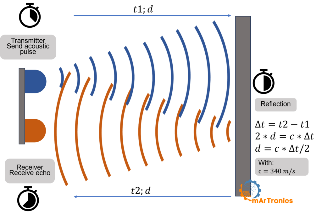
يرسل مستشعر الموجات فوق الصوتية نبضة صوتية عالية التردد بمعدل 40 كيلو هرتز (أعلى بكثير من السمع البشري) ثم يستمع إلى الصدى الذي يرتد من الأجسام القريبة. يخبرك الوقت بين النبضة والصدى بمدى بعد الجسم. وهذا أيضًا هو نفس المبدأ الذي تستخدمه الخفافيش للتنقل في الظلام، ويطلق عليه المهندسون طريقة وقت الرحلة.
كيفية عمل دورة القياس HC-SR04
يحتوي HC-SR04 على محولين طاقة أسطوانيين في المقدمة. واحد هو جهاز الإرسال (يرسل النبض) والآخر هو جهاز الاستقبال (يلتقط الصدى). تمر دورة القياس الواحدة بأربع مراحل.
الإرسال: أولاً، يرسل Arduino نبضة عالية مدتها 10 ميكروثانية إلى طرف TRIG. ردًا على ذلك، يطلق HC-SR04 دفقة من ثماني موجات صوتية بقوة 40 كيلو هرتز تنتشر للخارج في شكل مخروطي يبلغ عرضه حوالي 15 درجة.
الانعكاس: عندما تصطدم موجة الصوت بجسم ما، فإنها ترتد مرة أخرى باتجاه المستشعر. تعكس الأسطح الصلبة والمسطحة الصوت بشكل جيد. تعمل الأسطح الناعمة أو المائلة على تشتيت الإشارة، مما قد يضعف الصدى أو يتسبب في فقدان القراءات.
الاستقبال: بعد ذلك، يلتقط محول طاقة المستقبل الصدى العائد، ويحتفظ HC-SR04 بدبوس ECHO الخاص به عاليًا لمدة تساوي وقت السفر ذهابًا وإيابًا للموجة الصوتية.
حساب المسافة: وأخيرًا، يقرأ الأردوينو مدة دبوس ECHO باستخدام نبض في() ثم تطبق الصيغة: المسافة = (الزمن × سرعة الصوت) / 2. ينتقل الصوت بسرعة 0.034 سم تقريبًا في ميكروثانية (340 م/ث). تقسم على 2 لأن الصوت يذهب إلى الجسم ويعود، ويغطي المسافة مرتين. في الكود: المسافة = المدة * 0.034 / 2.
لماذا يقوم المؤازر بإنشاء مسح الرادار
يقوم جهاز الاستشعار بالموجات فوق الصوتية الثابت بقياس المسافة في اتجاه واحد فقط. ولكن إذا قمت بتثبيته على جهاز مؤازر وقمت بمسحه من 15 إلى 165 درجة، فستحصل على قراءة المسافة في كل زاوية. يقوم Arduino بعد ذلك بربط كل قياس بالزاوية المؤازرة وإرساله عبر التسلسل. قم برسم كل أزواج الزوايا والمسافة هذه وستحصل على عرض من أعلى إلى أسفل على غرار الرادار لكل ما هو موجود أمام المستشعر.
المكونات وفاتورة المواد
ستجد هنا كل المكونات التي تحتاجها للبنية الأساسية، بالإضافة إلى الجرس الاختياري ومعالجة ترقيات التصور. هذه كلها أجزاء شائعة ورخيصة يسهل أيضًا العثور عليها في أي بائع تجزئة للإلكترونيات.
| المكوّن | الغرض | هل هذا مطلوب؟ | الملاحظات |
|---|---|---|---|
| أردوينو أونو | لوحة المتحكم الرئيسي | نعم | تعمل أي لوحة متوافقة مع Uno |
| جهاز الاستشعار بالموجات فوق الصوتية HC-SR04 | قياس المسافة عبر النبضات فوق الصوتية | نعم | نطاق 2 سم إلى 400 سم |
| محرك مؤازر SG90 | يمسح المستشعر عبر قوس 180 درجة | نعم | جهاز مؤازر دقيق قياسي |
| اللوح | منصة النماذج الأولية بدون لحام | نعم | نصف الحجم أو الحجم الكامل |
| أسلاك التوصيل (M-M، M-F) | توصيل جميع المكونات | نعم | 10 أسلاك على الأقل |
| كابل USB (من النوع A إلى B) | تحميل الكود وربط البيانات التسلسلية | نعم | كابل Arduino USB قياسي |
| جرس بيزو | تنبيه مسموع للأجسام القريبة | اختياري | جرس نشط أو غير نشط |
| طابعة ثلاثية الأبعاد وخيوط (PLA/ABS) | حوامل المستشعرات والمؤازر المخصصة | اختياري | يعمل تركيب اللوح أيضاً |
| كمبيوتر مع Arduino IDE | كتابة وتحميل كود Arduino البرمجي | نعم | تنزيل Arduino IDE |
| كمبيوتر مزود بمعالج IDE | تصوير الرادار على الشاشة | اختياري | تحميل مجاني من موقع processing.org |
تصميم وطباعة حوامل مخصصة ثلاثية الأبعاد (اختياري)
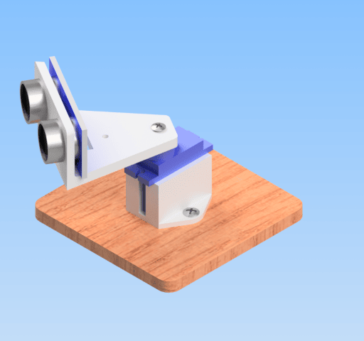
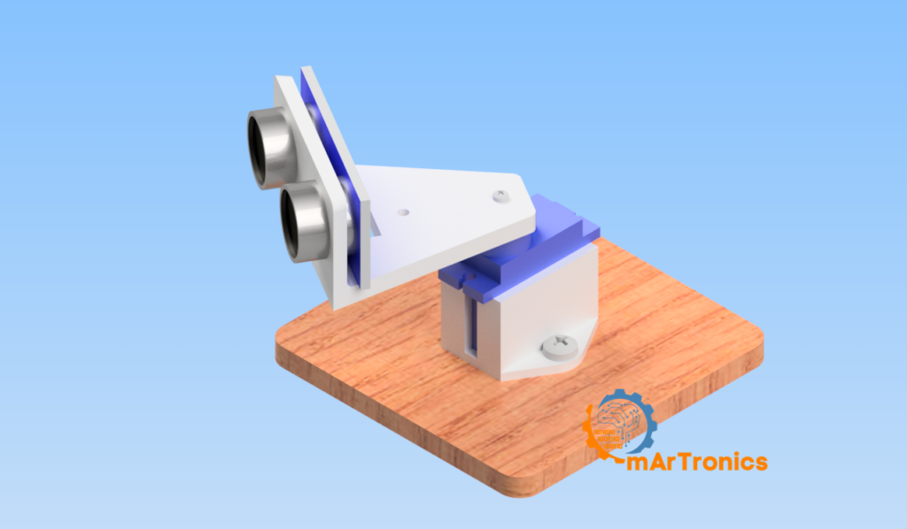
إذا كان لديك طابعة ثلاثية الأبعاد، فإن التركيبات المخصصة تجعل التصميم أكثر استقرارًا وتبدو أكثر نظافة. أي برنامج CAD يعمل لهذا الغرض (Autodesk Fusion 360، Tinkercad، وما إلى ذلك). ولكن إذا لم يكن لديك طابعة ثلاثية الأبعاد، فلا بأس بذلك أيضًا. سوف يحمل الشريط أو الغراء الساخن أو الروابط المضغوطة HC-SR04 على بوق المؤازرة أيضًا.
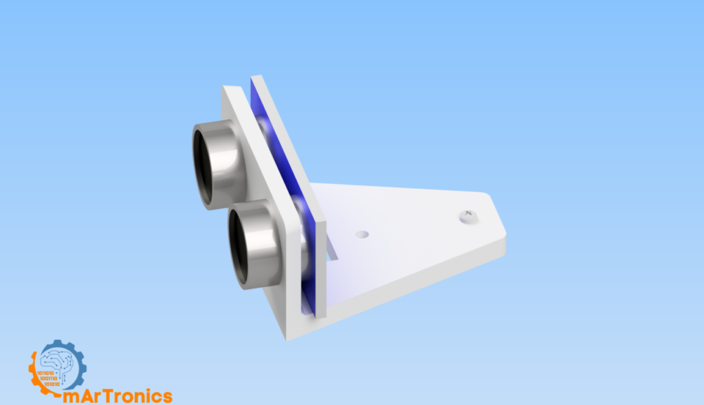
حامل المستشعر: صمم دعامة تحمل HC-SR04 بشكل مريح. اترك الجزء الأمامي مفتوحًا حتى يتمكن كلا المحولين من "الرؤية" للخارج دون عائق. يحتاج الجزء الخلفي إلى فتحة أو فتحة لولبية لتوصيله بقرن المؤازرة.
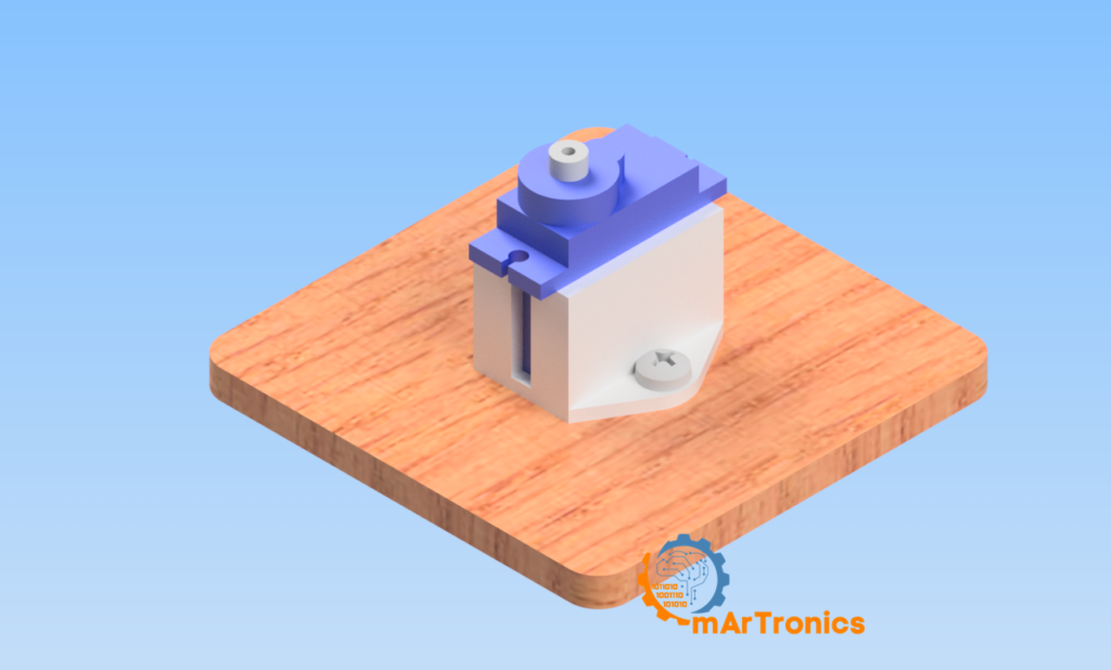
حامل مؤازر: قم بإنشاء قاعدة تحمل جسم المؤازرة بقوة. اجعلها واسعة ومسطحة بما يكفي للجلوس على طاولة أو تثبيتها على منصة. اجعل البوق المؤازر متاحًا في الأعلى حتى يتمكن المستشعر من الدوران بحرية. للحصول على نصائح حول الطباعة ثلاثية الأبعاد وأفكار التصميم، راجع موقعنا مقدمة في الطباعة ثلاثية الأبعاد والتصميم ثلاثي الأبعاد.
تجميع الأجهزة
بمجرد حصولك على المكونات (والتركيبات الاختيارية)، فإليك كيفية تجميعها معًا.
الخطوة 1 - قم بتركيب المستشعر: قم بتثبيت HC-SR04 في حامله المطبوع ثلاثي الأبعاد، أو قم بتثبيته على بوق المؤازرة. تأكد من عدم وجود أي شيء يغطي أيًا من محولي الطاقة.
الخطوة 2 - قم بتركيب المؤازر: ضع محرك المؤازرة في الحامل الأساسي الخاص به. إذا كنت لا تستخدم حامل مطبوع، فاضغط على جسم المؤازر في منطقة اللوح أو ثبته على الطاولة باستخدام معجون لاصق.
الخطوة 3 - قم بتوصيل المستشعر بالمؤازر: قم بتوصيل دعامة المستشعر بقرن المؤازرة باستخدام المسمار الصغير المتضمن مع المؤازرة، أو استخدم تصميمًا ملائمًا. تأكد من أن المستشعر يدور بسلاسة عندما يتحرك المؤازرة.
الخطوة 4 - قم بتوصيل الأسلاك: اتبع جدول الأسلاك في القسم التالي لتوصيل جميع المكونات بـ Arduino باستخدام اللوح وأسلاك التوصيل.
مخطط الأسلاك والتوصيلات الدبوسية
الأسلاك لهذا المشروع بسيطة. استخدم الجدول أدناه للبنية الأساسية، وإذا كنت تضيف الجرس، فقم بتضمين صف الجرس أيضًا. تحتاج جميع المكونات إلى مشاركة أرضية مشتركة من خلال طرف Arduino GND.
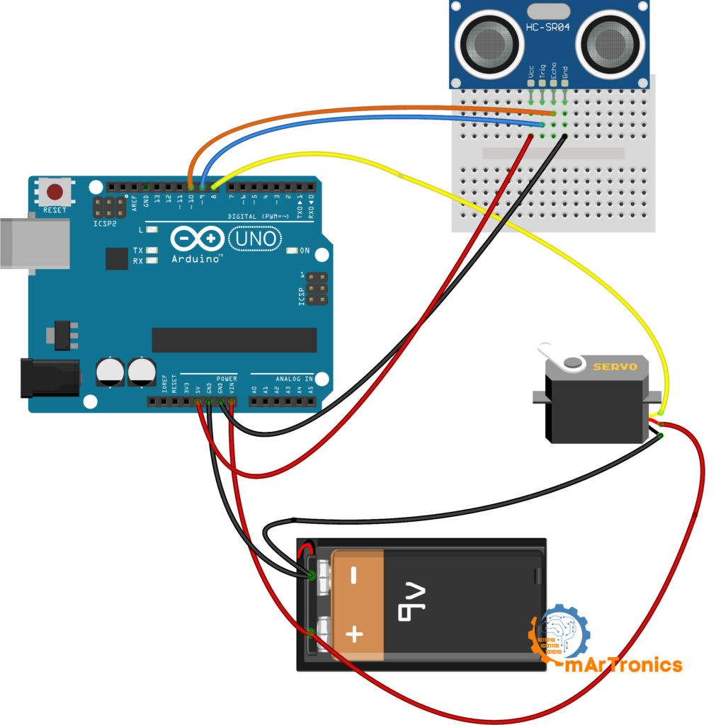
أسلاك الرادار الأساسية
| المكوّن | دبوس المكوّن | دبوس الأردوينو | الملاحظات |
|---|---|---|---|
| مؤازر SG90 | إشارة (برتقالي/أصفر) | الدبوس 8 | سلك التحكم في PWM |
| مؤازر SG90 | VCC (أحمر) | 5V | مزود الطاقة للمؤازر |
| مؤازر SG90 | GND (بني/أسود) | GND | أرضية مشتركة |
| HC-SR04 | VCC | 5V | طاقة المستشعر |
| HC-SR04 | GND | GND | أرضية مشتركة |
| HC-SR04 | مجموعة TRIG | الدبوس 9 | إخراج نبض الزناد |
| HC-SR04 | ECHO | الدبوس 10 | إدخال نبض الصدى |
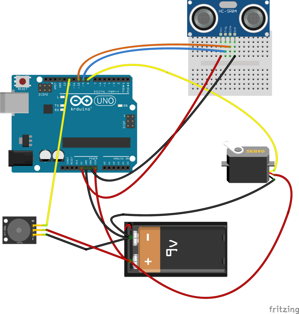
أسلاك الجرس الاختيارية
| المكوّن | دبوس المكوّن | دبوس الأردوينو | الملاحظات |
|---|---|---|---|
| جرس بيزو | موجب (+) | الدبوس 12 | سلك إشارة لإخراج النغمة |
| جرس بيزو | سالب (-) | GND | أرضية مشتركة |
مهم: يجب أن تذهب جميع اتصالات GND (المؤازرة، المستشعر، الجرس) إلى نفس سكة Arduino GND لأن المسارات الأرضية المنفصلة تسبب قراءات غير منتظمة للمستشعر وارتعاش المؤازرة. استخدم قضبان الطاقة الخاصة بلوحة التجارب لتوزيع 5V وGND.
كود أردوينو: رسم الرادار الأساسي
الرسم أدناه هو جوهر الرادار. يقوم بمسح المؤازرة من 15 إلى 165 درجة والعكس، مع قياس المسافة عند كل درجة. كل قراءة تخرج عبر التسلسل في التنسيق الزاوية، المسافة حتى يتمكن مخطط المعالجة (أو الشاشة التسلسلية) من تحليله.
/**
 * Arduino Ultrasonic Radar — Core Sketch
 * Author: Omar Draidrya
 * Date: 2024/05/09
 * This code controls a servo motor and measures distance
 * using an HC-SR04 ultrasonic sensor.
 */

#include <Servo.h>

Servo myServo;

const int trigPin = 9;
const int echoPin = 10;

long duration;
int distance;

void setup() {
  pinMode(trigPin, OUTPUT);
  pinMode(echoPin, INPUT);
  Serial.begin(9600);
  myServo.attach(8);
}

void loop() {
  // Forward sweep: 15 to 165 degrees
  for (int i = 15; i <= 165; i++) {
    myServo.write(i);
    delay(30);
    distance = calculateDistance();
    Serial.print(i);
    Serial.print(",");
    Serial.print(distance);
    Serial.print(".");
  }
  // Return sweep: 165 back to 15 degrees
  for (int i = 165; i > 15; i--) {
    myServo.write(i);
    delay(30);
    distance = calculateDistance();
    Serial.print(i);
    Serial.print(",");
    Serial.print(distance);
    Serial.print(".");
  }
}

int calculateDistance() {
  digitalWrite(trigPin, LOW);
  delayMicroseconds(2);
  digitalWrite(trigPin, HIGH);
  delayMicroseconds(10);
  digitalWrite(trigPin, LOW);
  duration = pulseIn(echoPin, HIGH);
  distance = duration * 0.034 / 2;
  return distance;
}
كيف يعمل كود رادار الأردوينو
منطق المسح المؤازر: اثنان for حلقات التعامل مع عملية الاجتياح. ينتقل أحدهما من 15 إلى 165 درجة، والآخر يعود من 165 إلى 15. النطاق هو 15-165 بدلاً من 0-180 لأن معظم الماكينات الرخيصة بها مناطق ميتة في الأطراف، وأيضًا لأن HC-SR04 يقرأ بشكل سيئ عند استهدافه مرة أخرى إلى قاعدة التثبيت الخاصة به. يمنح التأخير البالغ 30 مللي ثانية بين كل درجة الوقت المؤازر للاستقرار قبل القياس التالي.
حساب المسافة باستخدام النبض في (): إن حساب المسافة() ترسل الدالة نبضة عالية مدتها 10 ميكروثانية على طرف TRIG، ثم تتصل نبض في(echoPin، عالي). يتم حظر هذه الوظيفة حتى يصبح طرف ECHO مرتفعًا ويعيد مدة النبضة بالميكروثانية، وهو وقت السفر ذهابًا وإيابًا للموجة فوق الصوتية. الضرب في 0.034 يحول الميكروثانية إلى سنتيمترات (نظرًا لأن الصوت ينتقل بحوالي 0.034 سم/لنا). القسمة على 2 تعطي المسافة في اتجاه واحد.
الإخراج التسلسلي والاختبار
تنسيق الإخراج التسلسلي: يتم إرسال كل قراءة على أنها الزاوية، المسافة على سبيل المثال، 90,25. يعني أن المستشعر عند 90 درجة ويرى جسمًا على بعد 25 سم. الفترة . هو المحدد الذي يخبر مخطط المعالجة حيث تنتهي قراءة واحدة وتبدأ القراءة التالية. يمكنك التحقق من هذا الإخراج في Arduino IDE Serial Monitor بسرعة 9600 باود بعد التحميل.
الاختبار باستخدام الشاشة التسلسلية: قبل إعداد المعالجة، قم بتحميل هذا المخطط وافتح Serial Monitor (Tools > Serial Monitor) عند 9600 باود. يجب أن تشاهد دفقًا مستمرًا من أزواج الزاوية والمسافة مثل 15,40.16,38.17,35. التمرير عبر الشاشة. إذا رأيت أصفارًا أو أرقامًا كبيرة جدًا فقط، فتحقق من الأسلاك وراجع قسم استكشاف الأخطاء وإصلاحها أدناه.
ترقية اختيارية: إضافة جرس لتنبيهات العوائق
بمجرد أن يعمل الرادار الأساسي، يمكنك إضافة صفارة بيزو حتى تحصل على تحذير مسموع عندما يقترب جسم ما كثيرًا. فكر في الأمر مثل جهاز استشعار وقوف السيارات لمكتبك.
/**
 * Arduino Ultrasonic Radar — Buzzer Upgrade
 * Author: Omar Draidrya
 * Date: 2024/05/09
 * Adds a buzzer alert when an obstacle is within threshold distance.
 */

#include <Servo.h>

Servo myServo;

const int trigPin = 9;
const int echoPin = 10;
const int buzzerPin = 12;
const int alertThreshold = 10; // cm — change this value to adjust sensitivity

long duration;
int distance;

void setup() {
  pinMode(trigPin, OUTPUT);
  pinMode(echoPin, INPUT);
  pinMode(buzzerPin, OUTPUT);
  Serial.begin(9600);
  myServo.attach(8);
}

void loop() {
  for (int i = 15; i <= 165; i++) {
    myServo.write(i);
    delay(30);
    distance = calculateDistance();
    Serial.print(i);
    Serial.print(",");
    Serial.print(distance);
    Serial.print(".");

    if (distance <= alertThreshold) {
      tone(buzzerPin, 2000);
    } else {
      noTone(buzzerPin);
    }
  }
  for (int i = 165; i > 15; i--) {
    myServo.write(i);
    delay(30);
    distance = calculateDistance();
    Serial.print(i);
    Serial.print(",");
    Serial.print(distance);
    Serial.print(".");

    if (distance <= alertThreshold) {
      tone(buzzerPin, 2000);
    } else {
      noTone(buzzerPin);
    }
  }
}

int calculateDistance() {
  digitalWrite(trigPin, LOW);
  delayMicroseconds(2);
  digitalWrite(trigPin, HIGH);
  delayMicroseconds(10);
  digitalWrite(trigPin, LOW);
  duration = pulseIn(echoPin, HIGH);
  distance = duration * 0.034 / 2;
  return distance;
}
كيف يعمل الجرس: بعد كل قياس للمسافة، يتحقق الرمز مما إذا كانت القراءة عند مستوى أو أقل عتبة التنبيه (10 سم افتراضيا). إذا كان الأمر كذلك، نغمة(buzzerPin, 2000) يدفع الجرس عند 2000 هرتز. غير ذلك, عدم وجود نغمة() يطفئه. يمكنك التغيير عتبة التنبيه إلى أي مسافة تريد. على سبيل المثال، قم بتعيينه على 20 سم للتحذيرات السابقة، أو 5 سم إذا كنت تريد تشغيله فقط للأشياء القريبة جدًا.
ترقية اختيارية: تصوير الرادار في الوقت الحقيقي مع المعالجة
يعمل رادار Arduino بشكل جيد مع الشاشة التسلسلية فقط، ولكن من الممتع أكثر رؤية شاشة رادار حية. وهنا يأتي دور المعالجة. المعالجة هي بيئة برمجة مجانية مفتوحة المصدر مصممة للمشاريع المرئية والتفاعلية. نظرًا لأنه يقرأ البيانات التسلسلية من Arduino ويرسم الرسومات في الوقت الفعلي، فهو مناسب هنا بشكل طبيعي.
مهم: نظام الرادار يعمل بكامل طاقته دون معالجة. إذا كنت تريد فقط الأجهزة والإخراج التسلسلي، فتخط هذا القسم.
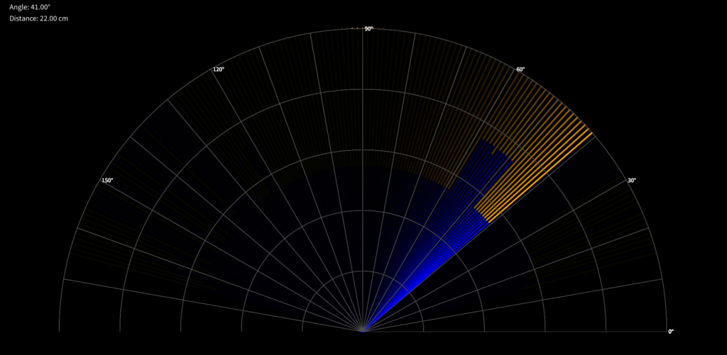
ما الذي يفعله رسم المعالجة
يفتح رمز المعالجة اتصالاً تسلسليًا مع Arduino عند 9600 باود، ويقرأ البيانات الواردة الزاوية، المسافة دفق البيانات، ثم يقوم بتحليل كل قراءة لرسم شاشة رادارية. ونتيجة لذلك، تظهر الكائنات المكتشفة كخطوط ملونة داخل حلقات قوسية تمثل نطاقات المسافة. يُظهر تراكب النص أيضًا الزاوية الحالية والمسافة المُقاسة.
كيفية إعداد المعالجة
الخطوة 1: قم بتحميل معرف المعالجة IDE وتثبيته من المعالجة.
الخطوة 2: أغلق شاشة Arduino IDE التسلسلية إذا كانت مفتوحة. يمكن لبرنامج واحد فقط استخدام المنفذ التسلسلي في المرة الواحدة.
الخطوة 3: انسخ رمز المعالجة أدناه إلى رسم جديد وقم بتشغيله.
الخطوة 4: إذا ظهرت شاشة الرادار ولكنها لم تظهر أي خط مسح، فستحتاج بعد ذلك إلى تغيير فهرس المنفذ التسلسلي. في الخط String portName = Serial.list()[0];قم بتغيير [0] to [1] or [2] بناءً على المنفذ الذي يعمل عليه Arduino الخاص بك. يمكنك طباعة Serial.list() إلى وحدة تحكم المعالجة لرؤية جميع المنافذ المتاحة.
كود رادار المعالجة
/**
 * Arduino Radar — Processing Visualization
 * Date: 2024/05/09
 * Reads serial data from Arduino and draws a radar display.
 */

import processing.serial.*;

Serial communicationPort;
String serialData = "";
float scanAngle = 0;
float scanDistance = 0;
int radarRadius = 800;
int maxDistance = 40; // cm

void setup() {
  size(1920, 1080);
  smooth();
  String portName = Serial.list()[0]; // Adjust index if needed
  communicationPort = new Serial(this, portName, 9600);
  communicationPort.bufferUntil('.');
  background(0);
}

void draw() {
  drawRadarBackground();
  if (serialData.length() > 0) {
    parseSerialData();
    drawDetection();
  }
  displayInfo(scanDistance, scanAngle);
}

void drawRadarBackground() {
  pushMatrix();
  translate(width / 2, height - 200);
  noFill();
  stroke(80);
  strokeWeight(1);
  for (int i = 0; i < 5; i++) {
    float r = radarRadius * (i + 1) / 5.0;
    arc(0, 0, r * 2, r * 2, PI, TWO_PI);
  }
  for (int i = 0; i < 180; i += 10) {
    float x = radarRadius * cos(radians(i));
    float y = radarRadius * sin(radians(i));
    line(0, 0, x, -y);
    if (i % 30 == 0) {
      fill(255);
      textSize(16);
      text(i + "°", x + 5, -y + 5);
    }
  }
  popMatrix();
}

void parseSerialData() {
  String[] tokens = serialData.split(",");
  if (tokens.length >= 2) {
    scanAngle = float(tokens[0]);
    scanDistance = float(tokens[1]);
  }
}

void drawDetection() {
  float angle = radians(scanAngle);
  float distance = scanDistance;
  float x = distance * 20;
  float fullX = radarRadius * cos(angle);
  float fullY = radarRadius * sin(angle);

  pushMatrix();
  translate(width / 2, height - 200);
  strokeWeight(4);
  noStroke();
  fill(0, 20);
  rect(-radarRadius, -radarRadius, radarRadius * 2, radarRadius);

  if (distance > 0 && distance <= maxDistance) {
    stroke(0, 0, 255);
    line(0, 0, x * cos(angle), -x * sin(angle));
    stroke(255, 165, 0);
    line(x * cos(angle), -x * sin(angle), fullX, -fullY);
  } else {
    stroke(0, 0, 255);
    line(0, 0, fullX, -fullY);
  }
  popMatrix();
  serialData = "";
}

void displayInfo(float distance, float angle) {
  fill(0);
  noStroke();
  rect(10, 10, 260, 80);
  fill(255);
  textSize(20);
  text("Angle: " + nf(angle, 1, 2) + "°", 30, 30);
  text("Distance: " + nf(distance, 1, 2) + " cm", 30, 60);
}

void serialEvent(Serial p) {
  serialData = p.readStringUntil('.');
  serialData = serialData.substring(0, serialData.length() - 1);
}
فهم تنسيق البيانات التسلسلية
يرسل Arduino البيانات بالتنسيق الدقيق الزاوية، المسافة على سبيل المثال، 45,18.. يستخدم رسم المعالجة المخزن المؤقت حتى (''.") لجمع الأحرف حتى يصل إلى الفاصل الزمني، ثم ينقسم على الفاصلة للحصول على الزاوية والمسافة. إذا تغير التنسيق ولو قليلاً، فسيتم فواصل التحليل. حتى إضافة مسافة واحدة تكفي لإيقاف الشاشة، لذا حافظ على مزامنة مخرجات Arduino ومحلل المعالجة.
المعايرة والدقة والقيود
بمجرد تشغيل الرادار، ستلاحظ أن الأداء في العالم الحقيقي أكثر فوضوية مما قد تتوقعه. تساعدك معرفة القيود على قراءة البيانات بشكل صحيح واستكشاف الأخطاء وإصلاحها عندما تبدو الأمور على غير ما يرام.
محاذاة المؤازرة: لا تتم معايرة معظم ماكينات الهوايات بشكل مثالي خارج الصندوق، لذا قد لا تشير الزاوية 90 إلى الأمام مباشرة على ماكيناتك المحددة. إذا بدت شاشة الرادار مستديرة أو متخالفة، فاضبط دعامة المستشعر الموجودة على آلة التنبيه أو أضف إزاحة صغيرة في الكود.
عرض مخروط الموجات فوق الصوتية: يصدر جهاز HC-SR04 صوتًا في مخروط بعرض 15 درجة تقريبًا، لذلك لا يمكنه التمييز بين جسمين إذا كانا قريبين من بعضهما البعض داخل هذا المخروط. قد تلاحظ أيضًا أن المستشعر يلتقط حافة جسم كبير حتى عندما لا يكون أمامك مباشرة.
أسطح عاكسة وناعمة: تنتج الأسطح المسطحة الصلبة مثل الجدران والصناديق أصداء قوية. لكن الأقمشة الناعمة والأسطح المائلة والأشياء الرقيقة مثل أرجل الكراسي تميل إلى امتصاص النبض أو حرفه، لذلك قد تفوتك قراءات أو مسافات خاطئة.
المدى والضوضاء وسرعة المسح
المدى الأقصى العملي: تشير ورقة بيانات HC-SR04 إلى 400 سم، لكن القراءات الموثوقة تصل إلى حوالي 200 سم. أبعد من ذلك، تصبح الأصداء ضعيفة للغاية. يبلغ حجم رسم المعالجة الافتراضي 40 سم، وهو ما يعمل بشكل جيد مع العروض التوضيحية على الطاولة.
قراءات صاخبة أو قافزة: تعتبر الارتفاعات العرضية في بيانات المسافة أمرًا طبيعيًا لأن الانعكاسات متعددة المسارات والضوضاء الكهربائية والأصداء العالقة من النبضات السابقة كلها تسبب هذه الارتفاعات. الحل البسيط هو إضافة مرشح متوسط قصير في كود Arduino الخاص بك والذي يأخذ ثلاث قراءات ثم يستخدم المتوسط.
سرعة المسح مقابل معدل التحديث: يعني التأخير البالغ 30 مللي ثانية لكل درجة أن عملية المسح الكاملة للأمام تستغرق حوالي 4.5 ثانية. إذا قمت بإسقاط التأخير، تصبح عملية المسح أسرع، ولكن يكون لدى المؤازرة وقت أقل للاستقرار وتصبح القراءات أكثر ضجيجًا. من ناحية أخرى، إذا قمت برفعه، تستقر القياسات ولكن يتم تحديث الرادار بشكل أبطأ. إنها مقايضة يمكنك ضبطها حسب احتياجاتك.
استكشاف المشكلات الشائعة وإصلاحها
إذا كان هناك شيء معطل، فاعمل من خلال قائمة التحقق هذه قبل تبديل أي جهاز.
المؤازر لا يتحرك أولاً، تأكد من أن سلك الإشارة موجود على الطرف 8 وأن VCC وGND ينتقلان إلى Arduino 5V وGND. ثم حاول رسم مسح أساسي من أمثلة Arduino Servo لمعرفة ما إذا كانت المشكلة تكمن في المؤازرة نفسها أم في رمز الرادار.
يقرأ HC-SR04 دائمًا 0 أو المسافة القصوى: أولاً، تحقق من أن TRIG على المنفذ 9 وأن ECHO على المنفذ 10. ثم تأكد من أن المستشعر يعمل على 5 فولت، وليس 3.3 فولت. تأكد أيضًا من أن الحامل لا يحجب محولات الطاقة. قم بتوجيه المستشعر إلى جدار مستوٍ على بعد حوالي 20 سم وتحقق من الشاشة التسلسلية.
قيم المسافة الصاخبة أو القافزة: أولاً، تأكد من توصيل جميع الأرضيات بنفس السكة، لأن أسلاك التوصيل الطويلة يمكن أن تلتقط الضوضاء الكهربائية. إذا استمرت القراءات في التقلب، قم بإضافة مكثف 10 فائق التوهج بين أطراف المستشعر VCC وGND لتثبيت الطاقة.
يتم تشغيل الجرس دائماً أو لا يتم تشغيله أبداً: تأكد من توصيل الجرس بالرقم 12 وتحقق من ذلك عتبة التنبيه القيمة في الكود. إذا قرأ المستشعر مسافات خاطئة (انظر أعلاه)، فسيعمل منطق الجرس بشكل سيء أيضًا. قم بإصلاح المستشعر أولاً.
المعالجة واستكشاف الأخطاء وإصلاحها التسلسلية
المعالجة غير متصلة أو تظهر شاشة فارغة: أولاً، قم بإغلاق Arduino Serial Monitor قبل تشغيل رسم المعالجة، نظرًا لأن برنامجًا واحدًا فقط يمكنه استخدام المنفذ التسلسلي في المرة الواحدة. إذا تم تشغيل المخطط ولكن بقي الرادار فارغًا، فقم بتغيير فهرس المنفذ Serial.list()[0] to [1] or [2]. مطبعة Serial.list() إلى وحدة تحكم المعالجة للعثور على المنفذ الصحيح.
عدم تطابق التنسيق التسلسلي: يتوقع رسم المعالجة بالضبط الزاوية، المسافة بدون مسافات. إذا قمت بتغيير اردوينو Serial.print() العبارات بأي طريقة (على سبيل المثال، عن طريق إضافة وحدات أو محددات إضافية أو مسافات)، فسوف ينقطع محلل المعالجة. لذا احتفظ دائمًا بالمزامنة بين الرسمين.
مشاكل في الطاقة أو سلوك غير منتظم عند تحرك المؤازرة: يمكن لسيرفو SG90 سحب ما يصل إلى 500 مللي أمبير تحت الحمل، لذلك إذا كان Arduino يعمل على طاقة USB وحدها، يمكن أن يتسبب المؤازرة في انخفاض الجهد الذي يؤدي إلى إعادة ضبط Arduino أو قراءات المستشعر الفاسدة. لإصلاح ذلك، قم بتشغيل المؤازرة من مصدر خارجي بجهد 5 فولت مع أرضية مشتركة مع Arduino.
الأسئلة الشائعة (FAQ)
يستخدم مشروع رادار Arduino مستشعرًا بالموجات فوق الصوتية مثبتًا على محرك سيرفو. يقوم المؤازرة بمسح المنطقة الأمامية، وقياس المسافة إلى الأشياء في كل زاوية. يرسل Arduino البيانات إلى جهاز كمبيوتر، والذي يعرضها على شكل مسح راداري على الشاشة. إنه مشروع اردوينو وسيط شائع.
نعم. يعد HC-SR04 هو الخيار الأكثر شيوعًا لأنه رخيص وموثوق. يمكنك أيضًا استخدام أجهزة استشعار مثل US-015 أو JSN-SR04T. تأكد من أن البديل يستخدم نفس واجهة TRIG/ECHO. إذا كان يستخدم بروتوكولًا مختلفًا (مثل I2C أو UART)، فستحتاج إلى تعديل كود Arduino.
تشير ورقة بيانات HC-SR04 إلى ما يصل إلى 400 سم (حوالي 13 قدمًا). ومن الناحية العملية، تصل القراءات الموثوقة إلى حوالي 200 سم. يبلغ حجم شاشة المعالجة الافتراضية 40 سم، وهو ما يعمل بشكل جيد مع العروض التوضيحية على سطح الطاولة. يمكنك زيادة الحد الأقصى للمسافة في مخطط المعالجة لإظهار نطاق أوسع.
لا، فالحوامل المطبوعة ثلاثية الأبعاد تجعل الأشياء أكثر ثباتًا ونظافة، ولكن يمكنك توصيل HC-SR04 بقرن المؤازرة باستخدام الغراء الساخن أو الشريط اللاصق أو الأربطة المضغوطة أو حتى الورق المقوى. يقوم الكثير من الأشخاص ببناء هذا المشروع بالكامل على اللوح.
تحتوي معظم الماكينات ذات الميزانية المحدودة على مناطق ميتة أو عزم دوران منخفض بالقرب من 0 و180 درجة. يؤدي تحديد المسح إلى 15-165 درجة إلى إبقاء المؤازرة في نطاقه الموثوق به ويمنع المستشعر من الإشارة للخلف نحو قاعدة التركيب الخاصة به، الأمر الذي قد ينتج عنه قراءات خاطئة.
نعم. يعمل الكود مع Arduino Nano وMega ومعظم اللوحات الأخرى المعتمدة على AVR. تأكد من تطابق أرقام الدبوس وأن اللوحة توفر 5 فولت للمستشعر والمؤازرة.
في الرسم التخطيطي للجرس، أوجد الخط const int int alertThreshold = 10; وغيّر القيمة إلى أي مسافة (بالسنتيمتر) تريدها. على سبيل المثال، ضبطها على 25 يعني أن الجرس سينشط كلما كان الجسم في نطاق 25 سم.
يعني هذا عادةً أن المعالجة متصلة بمنفذ تسلسلي خاطئ. اطبع Serial.list() في وحدة تحكم المعالجة، وابحث عن المنفذ الذي يستخدمه Arduino (مثل COM3 على Windows أو /dev/ttyUSB0 على Linux)، وقم بتحديث الفهرس في Serial.list()[0]. قم أيضًا بإغلاق Arduino Serial Monitor أولاً، حيث لا يمكن لبرنامجين مشاركة نفس المنفذ التسلسلي.
نعم إلى حد ما. يكتشف HC-SR04 أي شيء يعكس الموجات الصوتية، بما في ذلك الأشخاص والحيوانات الأليفة والأثاث. ومع ذلك، فإن الأجسام الرقيقة أو الناعمة مثل فراء القطة البعيدة قد لا تنتج صدى قويًا. للحصول على كشف بشري أكثر موثوقية على نطاقات أطول، انظر إلى وحدة رادار الموجات الدقيقة أو مستشعر LiDAR.
في ظل الظروف المثالية (سطح مستو، درجة حرارة الغرفة، عدم وجود تداخل)، يتمتع HC-SR04 بدقة مقدرة تبلغ حوالي 3 مم. من الناحية العملية، توقع الدقة في حدود 1 إلى 2 سم للمسافات التي تقل عن 100 سم. تنخفض الدقة عند النطاقات الأطول ومع الأسطح الزاوية أو الناعمة.
الموارد ذات الصلة
تغطي هذه الروابط المكونات الفردية المستخدمة في هذا المشروع، ويمكنها أيضًا مساعدتك في العثور على تصميمك التالي.
- مستشعر المسافة بالموجات فوق الصوتية Arduino: برنامج تعليمي HC-SR04 مع الأسلاك والرمز - يغطي جهاز HC-SR04 بالتفصيل، بما في ذلك الأسلاك والرمز والأخطاء الشائعة.
- دليل التحكم المؤازر الأردوينو: SG90، و PWM، و PCA9685 - كل شيء عن قيادة المحركات المؤازرة باستخدام Arduino، بما في ذلك محرك PCA9685 للمشاريع متعددة المحركات.
- أساسيات برمجة الأردوينو: الدليل الكامل للمبتدئين - إذا كنت جديدًا على شيفرة Arduino، ابدأ من هنا للتعرف على الإعداد()، والحلقة()، والمتغيرات، والشاشة التسلسلية.
- ما هو الأردوينو؟ - نظرة عامة ملائمة للمبتدئين على منصة Arduino ولوحاتها ونظامها البيئي.
- مقدمة في الطباعة ثلاثية الأبعاد والتصميم ثلاثي الأبعاد باستخدام المخترع - تعلم كيفية تصميم وطباعة القطع الخاصة بك لمشاريع الإلكترونيات.
- بناء سيارة روبوت لتجنب العقبات باستخدام الأردوينو - مشروع آخر يستخدم HC-SR04 ومؤازرة للملاحة المستقلة.
- بناء روبوت يتبع الخط باستخدام مستشعرات KY-033 - مشروع روبوتات للمبتدئين لتجربته بعد الانتهاء من الرادار.
- الذراع الروبوتية ذات 6 أبعاد - طباعة ثلاثية الأبعاد، وتوصيل أسلاك وبرمجة - مشروع متقدم متعدد المؤازر يعتمد على مهارات المؤازرة المستخدمة في هذا البرنامج التعليمي.
الخاتمة والخطوات التالية
نظرًا لأن المهارات من هذا المشروع (قراءة أجهزة الاستشعار، والتحكم في المحركات، والاتصال التسلسلي، وعرض البيانات) تظهر في معظم مشاريع الروبوتات والأنظمة المدمجة، سيكون لديك أساس متين لأي شيء تقوم ببنائه بعد ذلك.
لشيء مختلف، حاول بناء سيارة روبوت تتفادى العقبات يستخدم نفس جهاز الاستشعار بالموجات فوق الصوتية ومجموعة المؤازرة للتنقل من تلقاء نفسه. المزيد من دروس Arduino والروبوتات موجودة على الصفحة الرئيسية لأوم أرترونيكس.
تنزيل ملفات الطباعة ثلاثية الأبعاد (STL)
جميع ملفات STL القابلة للطباعة ثلاثية الأبعاد لهذا المشروع متاحة للتنزيل من متجرنا أو على Cults3D:
- متجر OmArTronics: قم بتنزيل ملفات المشروع من OmArTronics - احصل على حزمة المشروع الكاملة بما في ذلك ملفات STL ومخططات الأسلاك وكود المصدر التي يتم تسليمها إلى بريدك الإلكتروني.
- الطوائف3D: عرض على Cults3D - تصفح وتنزيل ملفات النماذج ثلاثية الأبعاد على Cults3D.