
This post contains affiliate links, marked with *. As an Amazon Associate I earn from qualifying purchases, at no extra cost to you. It helps keep the tutorials free.
The video loads from YouTube (Google), which may set cookies. Privacy policy
Quick summary
How the HC-SR04 ultrasonic distance sensor works and how to connect it to an Arduino Uno. Covers how the sensor times its echo, the wiring, a first program that prints the distance on your computer, a second program that shows it on a small display, the sensor’s limits and troubleshooting. Range: 2 cm to 400 cm.
The HC-SR04 measures distance with ultrasound, without touching the object, and connects to an Arduino with four wires.
How Ultrasonic Distance Sensing Works
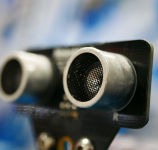
An ultrasonic sensor measures distance by sending out a short burst of high-frequency sound and listening for the echo that bounces back. Bats locate objects the same way. This is called echolocation. The HC-SR04 has two round transducers on its front: the transmitter (marked T) and the receiver (marked R). A transducer converts an electrical signal into sound, or sound into an electrical signal.
The Time-of-Flight Principle
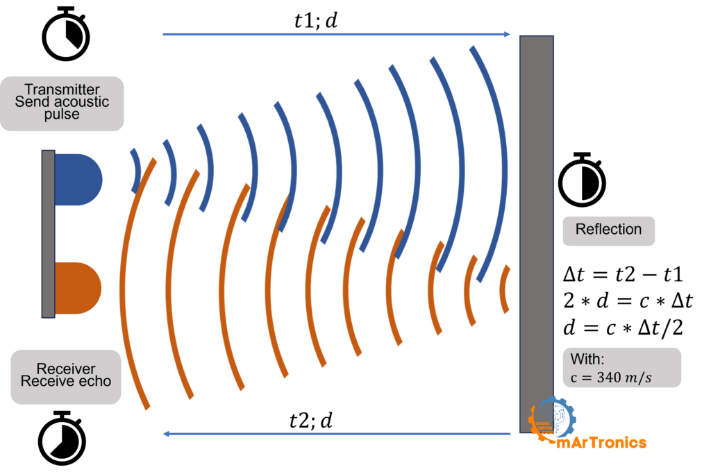
When you trigger the sensor, the transmitter sends a short burst of eight ultrasonic pulses at 40 kHz (kilohertz, 40,000 vibrations per second). Humans hear only up to about 20 kHz. The sound waves travel outward in a cone shape. When they hit a solid object, they bounce back toward the sensor, and the receiver picks them up as an echo. The sensor measures the time between sending the burst and receiving the echo. This is called the time of flight.
The Distance Formula
Because the sound travels to the object and back, it covers the distance twice. To get the one-way distance, you use this formula:
Distance = (Time × Speed of Sound) / 2.
At room temperature (around 20 °C), sound travels at about 343 m/s (meters per second), or 0.0343 cm per microsecond (µs, one millionth of a second). The Arduino measures the echo time in µs, so the formula in the code is:
Distance (cm) = duration (µs) × 0.0343 / 2.
Without the division by 2, the result is twice the real distance. The speed of sound depends on the air temperature. The code assumes 343 m/s (20 °C); the error this causes at other temperatures is listed under Environmental factors below. For the theory in more depth, with measured data, see my HC-SR04 with ESP32 guide.
Interactive Animation: How Ultrasonic Sensing Works
Click Send Ping and drag the Obstacle Distance slider to see how the HC-SR04 measures distance in real time.
HC-SR04 Specifications
| Parameter | Value |
|---|---|
| Operating voltage | 5 V DC |
| Operating current | 15 mA |
| Measuring range | 2 cm to 400 cm |
| Measuring angle | About 15 degrees |
| Ultrasonic frequency | 40 kHz |
| Trigger pulse width | 10 µs minimum |
| Accuracy | About ±3 mm |
| Interface pins | VCC, Trig, Echo, GND |
Components Needed
| Component | Purpose | Required? | Notes |
|---|---|---|---|
| Arduino Uno | Runs the code and reads the sensor | Yes | Any 5 V Arduino board works, for example the Uno, Nano or Mega. For 3.3 V boards such as the ESP32, see the FAQ. What is Arduino? |
| HC-SR04 ultrasonic sensor | Measures distance with ultrasound | Yes | Four-pin module: VCC, Trig, Echo, GND |
| Breadboard | Solderless platform for the connections | Yes | A half-size breadboard is enough |
| Jumper wires (male-to-male) | Connect the sensor to the Arduino through the breadboard | Yes | At least 4 wires |
| USB cable (Type A to B) | Connects the Arduino to your computer for uploading code and serial output | Yes | Included with most Arduino kits |
| 16×2 character LCD (HD44780) with I2C adapter | Shows distance readings without a computer | Optional | Only for the LCD section. LCD stands for liquid crystal display. 16×2 means 16 characters in 2 rows, and HD44780 is the controller chip of the display. The I2C adapter connects the display to the Arduino with two signal wires. |
Wiring the HC-SR04 to Arduino
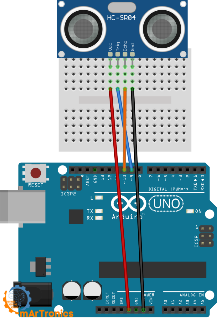
Connect the four sensor pins as shown in the table. Press every jumper wire firmly into the breadboard before you upload code.
| HC-SR04 pin | Arduino pin | Description |
|---|---|---|
| VCC | 5 V | Powers the sensor (must be 5 V) |
| Trig | Digital pin 9 | Receives the trigger signal from the Arduino |
| Echo | Digital pin 10 | Sends the echo pulse back to the Arduino |
| GND | GND | Common ground (must be shared with the Arduino GND) |
Important: The Arduino and the HC-SR04 must share a common ground. If you forget GND, the sensor gives no readings. Check this connection first if you see 0 cm or no output.
Arduino Ultrasonic Sensor Code
With the wiring done, upload this sketch (an Arduino program) to your board. You write and upload sketches in the Arduino IDE (integrated development environment), an application on your computer. The sketch triggers the HC-SR04, reads the echo time, calculates the distance in centimeters, and prints the result to the Serial Monitor. The Serial Monitor is a window in the Arduino IDE that shows the text the board sends over USB. New to Arduino code? My Arduino programming basics guide covers IDE setup and sketch structure.
/**
 * Author: Omar Draidrya
 * Date: 2024/05/07
 * This code measures distance using an ultrasonic sensor
 * and outputs the result via serial communication.
 */

#define TRIG_PIN  9   // Trigger pin of the ultrasonic sensor
#define ECHO_PIN  10  // Echo pin of the ultrasonic sensor

void setup() {
  pinMode(TRIG_PIN, OUTPUT);
  pinMode(ECHO_PIN, INPUT);
  Serial.begin(9600);
}

void loop() {
  long duration, distance;

  digitalWrite(TRIG_PIN, LOW);
  delayMicroseconds(2);

  digitalWrite(TRIG_PIN, HIGH);
  delayMicroseconds(10);
  digitalWrite(TRIG_PIN, LOW);

  duration = pulseIn(ECHO_PIN, HIGH);

  distance = duration * 0.0343 / 2;

  Serial.print("Distance (cm): ");
  Serial.println(distance);

  delay(1000);
}
Code Explanation: Line by Line
#define TRIG_PIN 9 and ECHO_PIN 10 give readable names to the pin numbers: pin 9 controls the trigger, and pin 10 listens for the echo. You can change these to any free digital pins, as long as you also update the wiring.
pinMode(TRIG_PIN, OUTPUT) sets pin 9 as an output, because the Arduino sends the start signal to the sensor.
pinMode(ECHO_PIN, INPUT) sets pin 10 as an input, because the Arduino reads the echo signal from the sensor.
Serial.begin(9600) opens serial communication at 9600 baud (bits per second) so the Arduino can send distance readings to your computer.
The trigger sequence: The Arduino sets the Trig pin LOW (0 V) and waits 2 µs so the pulse starts from a clean LOW level. It then sets the pin HIGH (5 V) for 10 µs and back to LOW. This 10 µs HIGH pulse tells the HC-SR04 to send its ultrasonic burst.
Reading the Echo and Calculating Distance
pulseIn(ECHO_PIN, HIGH) is a built-in Arduino function. It waits for the Echo pin to go HIGH, then measures how long the pin stays HIGH, in µs. That duration is the round-trip time of the sound. If the Echo pin does not go HIGH within 1 second (the default timeout of pulseIn()), the function returns 0 and the sketch prints 0 cm. This usually points to a wiring or power problem. If the sensor fires but no echo returns, most HC-SR04 modules keep Echo HIGH for about 38 ms, which this sketch prints as roughly 650 cm.
distance = duration * 0.0343 / 2 converts the echo time to a distance in centimeters. Here, 0.0343 is the speed of sound in cm per µs (343 m/s converted), and dividing by 2 accounts for the round trip. Because distance is declared as long (a whole-number type), the decimal part is cut off, so the Serial Monitor shows whole centimeters only. Declare distance as float to see decimal places.
Serial.println(distance) prints the distance followed by a new line, so each reading appears on its own row in the Serial Monitor.
delay(1000) pauses for one second before the next measurement. You can lower this for faster updates. Keep at least 60 ms between readings (the measurement cycle recommended in the HC-SR04 datasheet) so that old echoes do not disturb the next measurement.
Testing with the Serial Monitor
After uploading, open the Serial Monitor (Ctrl+Shift+M, or Tools > Serial Monitor). Set the baud rate dropdown in the Serial Monitor to 9600. Point the sensor at a flat surface like a wall or a book and slowly move it closer and farther away. The distance should update every second. For the video I checked the readings with a ruler: I held a board 4 cm from the sensor, then moved it farther away, and the reading changed to about 8 cm. If you get 0 or jumping numbers, check the wiring and the troubleshooting section below.
Optional Upgrade: Display Distance on an I2C LCD
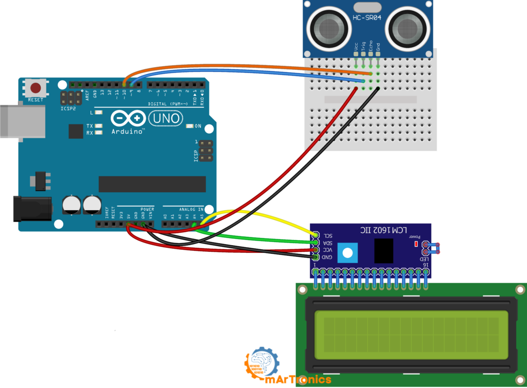
Once the Serial Monitor version works, you can add the 16×2 LCD with its I2C adapter. The readings then appear on the display without a computer. I2C is a two-wire bus: SDA carries the data, SCL the clock signal.
LCD Wiring Table
Keep the HC-SR04 connected as before (Trig on pin 9, Echo on pin 10, VCC to 5 V, GND to GND). Then add the LCD connections below. On a Mega, connect SDA to pin 20 and SCL to pin 21 instead of A4 and A5.
| I2C LCD pin | Arduino pin | Description |
|---|---|---|
| VCC | 5 V | Powers the LCD module |
| GND | GND | Common ground |
| SDA | A4 | I2C data line |
| SCL | A5 | I2C clock line |
Note on I2C addresses: Most I2C LCD modules use address 0x27, some use 0x3F. If the LCD stays blank after uploading, change the address in the code. If neither address works, run an I2C scanner sketch, a short program that prints the address of every connected I2C device to the Serial Monitor. My module worked with 0x27, the address in the sketch below.
LCD Arduino Code with NewPing Library
This sketch uses two libraries (ready-made code packages that you install once): NewPing for the sensor readings and LiquidCrystal_I2C for the LCD. Install both before uploading: Sketch > Include Library > Manage Libraries. The Library Manager lists the LCD library as “LiquidCrystal I2C” by Frank de Brabander. Other libraries with the same name use different commands, so the lcd.init() call in this sketch may not compile with them. NewPing handles the trigger and echo timing for you and stops waiting once the echo would exceed a maximum distance that you set in the sketch. Its ping_median() function takes several readings, discards out-of-range values and returns the median.
/**
 * Author: Omar Draidrya
 * Date: 2024/05/07
 * This code measures distance using an ultrasonic sensor
 * and displays the result on an LCD.
 */

#include <LiquidCrystal_I2C.h>
#include <NewPing.h>

#define TRIGGER_PIN  9
#define ECHO_PIN     10
#define MAX_DISTANCE 200

LiquidCrystal_I2C lcd(0x27, 16, 2);
NewPing sonar(TRIGGER_PIN, ECHO_PIN, MAX_DISTANCE);

void setup() {
  lcd.init();
  lcd.backlight();
  lcd.clear();
  lcd.setCursor(0, 0);
  lcd.print("Distance:");
}

void loop() {
  delay(50);
  int distance = sonar.ping_cm();

  lcd.setCursor(0, 1);
  lcd.print("                "); // 16 spaces clear the second row
  lcd.setCursor(0, 1);
  if (distance > 0) {
    lcd.print(distance);
    lcd.print(" cm    ");
  } else {
    lcd.print("Out of range    ");
  }
}
TRIGGER_PIN is the same pin 9 as TRIG_PIN in the first sketch. This sketch uses the name from the NewPing examples.
MAX_DISTANCE 200 limits the measurement to 200 cm (the sensor itself reaches up to 400 cm). Beyond this limit, or when no echo returns, sonar.ping_cm() returns 0 and the LCD shows “Out of range”.
delay(50) waits 50 ms before each measurement. The measurement and the LCD output add their own time, so two pings are always more than 60 ms apart, the minimum named under delay(1000) above.
The two lines before the if write 16 spaces into the second row and set the cursor back to its start. Without them, a shorter text leaves characters of the previous one on the screen. After “Out of range”, for example, a reading of 45 cm shows as “45 cm” followed by “nge”, the last letters of the old text.
The I2C adapter needs only two signal wires (SDA and SCL). Without the adapter, the LCD needs six: four data lines and two control lines, a wiring called 4-bit parallel mode. More digital pins stay free for other sensors or actuators (parts that move something, such as motors). For another project with an I2C LCD, see my Arduino password door lock project.
Accuracy, Limitations, and Best Practices
These physical limits explain most unexpected readings:
Minimum range (blind zone): The HC-SR04 cannot measure objects closer than about 2 cm. At that distance, the outgoing pulse and the returning echo overlap, and the receiver cannot tell them apart.
Soft and angled surfaces: Ultrasonic waves reflect best off hard, flat surfaces at a right angle to the sound beam. Soft materials like fabric, foam, or fur absorb much of the sound energy. Curved or angled surfaces can deflect the echo away from the receiver entirely.
Narrow detection cone: The HC-SR04 detects objects within a cone of about 15 degrees. It does not detect anything outside this cone, so point the sensor directly at the area you want to monitor.
Environmental factors: The speed of sound changes with air temperature and humidity. It rises by about 0.6 m/s per °C: at 0 °C it is about 331 m/s, at 30 °C about 349 m/s. The code assumes 343 m/s (20 °C), so at 0 °C a real distance of 1 m reads as about 103.5 cm. For most indoor projects at room temperature, 343 m/s is close enough.
Alignment and mounting: Mount the sensor so that the transducers face the target area. A sensor tilted away from a smooth surface can lose the echo, because the sound reflects to the side instead of back to the receiver. On mobile robots, fix the sensor rigidly so it does not vibrate while driving. In my ESP32 build I first propped the sensor against a battery pack and wondered why readings kept dropping out.
Troubleshooting Common HC-SR04 Problems
Wiring and Hardware Issues
Always reading 0 cm: The Echo pin never went HIGH within the pulseIn() timeout. First, check that the Echo wire goes to the correct pin (pin 10 in the wiring above). Then verify that the sensor GND is connected to the Arduino GND.
Always reading about 650 cm or “Out of range”: No echo arrives. The pulseIn() sketch then prints roughly 650 cm, and the NewPing sketch shows “Out of range” on the LCD. The sensor faces open space, or the target absorbs or deflects the sound.
Random jumping values: Usually caused by loose jumper wires, bad breadboard contacts, stray echoes from other objects inside the 15-degree cone, electrical noise, or other ultrasonic sensors nearby. Press all wires firmly into the breadboard. If the values still jump, keep at least 60 ms between readings and average several readings, or use NewPing’s ping_median() function, which returns the median of several pings. In my ESP32 build one reading jumped from 22.3 cm to 32.7 cm and back within two samples, although the target had not moved that far. A median of three or five readings removes single spikes like this.
Insufficient power: The HC-SR04 needs a stable 5 V supply. If many components run from the Arduino 5 V pin, the voltage can drop too low for the sensor.
Code and Configuration Issues
No serial output at all: Check that you selected the correct board and port in the Arduino IDE under Tools. The Serial Monitor baud rate must match the value in your code (9600).
Wrong pin assignment in code: If you wired Trig and Echo to pins other than 9 and 10, update the #define lines at the top of the sketch to match.
LCD not showing text: First turn the contrast potentiometer (the small adjustment screw on the back of the I2C adapter). Then check the I2C address (0x27 or 0x3F, see the note in the LCD section) and that SDA goes to A4 and SCL to A5 (pins 20 and 21 on a Mega).
Frequently Asked Questions (FAQ)
Up to about 400 cm (4 m), but readings past 200 to 300 cm get less reliable, especially in rooms with competing echoes or soft surfaces. My own longest measurement so far was about 1 m, so I have not tested the upper range myself.
Not directly. The standard HC-SR04 needs 5 V on VCC, and its Echo pin outputs 5 V, which can damage a 3.3 V input. Add a voltage divider (two resistors that reduce the voltage) on Echo, for example 1 kΩ in series and 2.2 kΩ to GND. That gives about 3.4 V, below the 3.6 V maximum of the ESP32 inputs. Or use the HC-SR04P, which runs on 3.3 V to 5 V. Details are in my HC-SR04 with ESP32 guide.
About ±3 mm under ideal conditions. In practice, expect closer to ±1 cm depending on the target surface and environment.
Yes. Give each sensor its own Trig and Echo pins and trigger them one after another, at least 60 ms apart, so that one sensor does not pick up the echo of another (acoustic crosstalk).
What to Build Next
Mount the sensor on a servo motor and build an Arduino ultrasonic radar that sweeps and maps the area around it. Or use it in an obstacle-avoiding robot car that drives around objects on its own. My Arduino servo control guide shows how to connect and control a servo.
1 thought on “Arduino Ultrasonic Distance Sensor: HC-SR04 Tutorial with Wiring and Code”