
Have you ever wanted to build your own radar system that detects nearby objects and displays them on screen, just like the real thing? In this step-by-step Arduino radar tutorial, you will build a fully working ultrasonic radar. You will use an أردوينو أونو, an HC-SR04 ultrasonic distance sensor, and a servo motor. The servo sweeps the sensor across a 180-degree arc. Meanwhile, the Arduino measures the distance to objects at each angle. The result is a scanning radar system that sends live data to your computer, where an optional Processing sketch draws a real-time radar display.
This Arduino radar project is one of the most popular beginner-to-intermediate builds in the Arduino community, and for good reason. It combines sensor reading, motor control, serial communication, and data visualization in one project. Whether you are a beginner or looking for a rewarding weekend build, this project teaches practical skills. You will reuse these skills in dozens of future projects.
ما ستتعلمه
- How an ultrasonic radar system works using the time-of-flight principle
- How to wire an HC-SR04 ultrasonic sensor and a servo motor to an Arduino Uno
- How to write Arduino code that sweeps the servo and measures distance at each angle
- How serial data is formatted and sent from the Arduino to a computer
- How to add a buzzer as an optional obstacle alert
- How to visualize the radar scan in real time using the Processing IDE (optional)
- How to calibrate, test, and troubleshoot your radar system
Project Overview: How the Arduino Radar System Works
Before you start building, first understand the big picture. This Arduino ultrasonic radar project has four main parts that work together in a loop.
ال محرك سيرفو rotates the HC-SR04 sensor back and forth. It sweeps from 15 to 165 degrees. If you are new to servo motors, see our دليل التحكم في محرك سيرفو باستخدام أردوينو. It explains how servos work and how to wire them.
At every degree of rotation, the مستشعر الموجات فوق الصوتية HC-SR04 fires a pulse and listens for the echo. It then calculates the distance to the nearest object. For a full primer on the HC-SR04, visit our Arduino ultrasonic distance sensor tutorial.
ال أردوينو أونو controls the entire process. It commands the servo, triggers the sensor, and calculates the distance. Then it sends the angle and distance data over serial to the computer. New to Arduino programming? Our دليل أساسيات برمجة أردوينو covers setup(), loop(), variables, and the Serial Monitor.
Optional Add-Ons
On the computer side, a Processing sketch (optional) reads the serial data and draws a sweeping radar display with arcs, scan lines, and object indicators. Specifically, this is the visual payoff of the project. However, the radar system works perfectly fine without it. You can verify all readings directly in the Arduino Serial Monitor.
Finally, a piezo buzzer can optionally sound an audible alert whenever the sensor detects an object within a configurable distance threshold.
The Principle of Ultrasonic Sensing
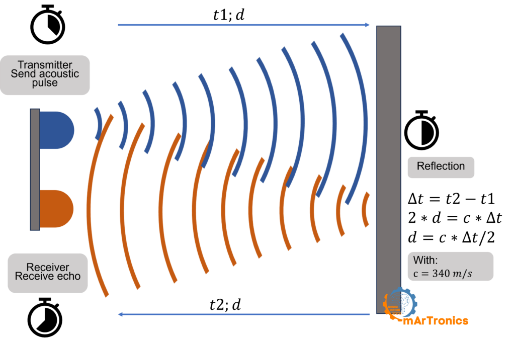
An ultrasonic sensor emits a high-frequency sound pulse, typically at 40 kHz (well above human hearing). Then, it listens for the echo that bounces back from nearby objects. By measuring the time between emission and echo return, the sensor calculates how far away the object is. In other words, this is the same principle bats use to navigate in the dark. Engineers call it the time-of-flight method.
How the HC-SR04 Measurement Cycle Works
The HC-SR04 module has two cylindrical transducers on the front. One is the transmitter, which emits the ultrasonic pulse. The other is the receiver, which detects the returning echo. The entire measurement cycle works in four stages.
Transmission: First, the Arduino sends a 10-microsecond HIGH pulse to the TRIG pin of the HC-SR04. This tells the sensor to emit a burst of eight 40 kHz sound waves. As a result, the sound spreads outward in a cone-shaped pattern about 15 degrees wide.
Reflection: Next, when the sound wave hits an object, it bounces back toward the sensor. The shape, size, and surface material of the object all affect the reflected wave. Hard, flat surfaces reflect sound strongly, while soft or angled surfaces tend to scatter the signal.
Reception: Subsequently, the receiver transducer detects the returning echo, and the HC-SR04 sets its ECHO pin HIGH for a duration equal to the round-trip travel time of the sound wave.
Distance calculation: Finally, the Arduino reads the ECHO pin duration using pulseIn(). It then applies the formula: المسافة = (الزمن × سرعة الصوت) / 2. The speed of sound in air is approximately 0.034 cm per microsecond (340 m/s). You must divide by 2 because the sound travels to the object and back, covering the distance twice. In code, this becomes المسافة = المدة * 0.034 / 2.
Why the Servo Creates a Radar Sweep
A single stationary ultrasonic sensor only measures the distance in one direction. By mounting the HC-SR04 on a servo motor and sweeping it from 15 to 165 degrees, you get a distance measurement at every degree. The Arduino pairs each measurement with the current servo angle and sends it over serial. Plotting all these angle-distance pairs gives you a top-down radar-like view of the area ahead. This is what makes the project function like a real scanning radar system.
Components and Bill of Materials
The following table lists every component you need for the core radar build. Additionally, it includes the optional upgrades for the buzzer alert and Processing visualization. All of these are common, inexpensive parts that you can find at any electronics retailer.
| عنصر | غاية | مطلوب؟ | ملحوظات |
|---|---|---|---|
| أردوينو أونو | لوحة التحكم الدقيقة الرئيسية | نعم | Any Uno-compatible board works |
| مستشعر الموجات فوق الصوتية HC-SR04 | Measures distance via ultrasonic pulses | نعم | Range 2 cm to 400 cm |
| SG90 Servo Motor | Sweeps the sensor across a 180-degree arc | نعم | Standard micro servo |
| لوح التجارب | Solderless prototyping platform | نعم | Half-size or full-size |
| Jumper Wires (M-M, M-F) | Connecting all components | نعم | At least 10 wires |
| كابل USB (من النوع A إلى النوع B) | Upload code and serial data link | نعم | Standard Arduino USB cable |
| Piezo Buzzer | Audible alert for close objects | خياري | Active or passive buzzer |
| 3D Printer and Filament (PLA/ABS) | Custom sensor and servo mounts | خياري | Breadboard mounting also works |
| Computer with Arduino IDE | Writing and uploading Arduino code | نعم | Download Arduino IDE |
| Computer with Processing IDE | Radar visualization on screen | خياري | Free download at processing.org |
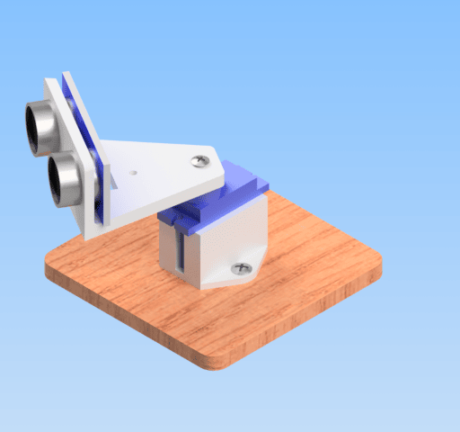
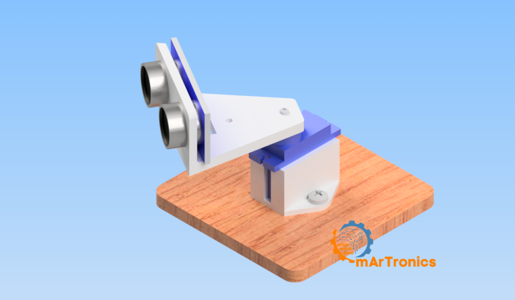
Designing and 3D Printing Custom Mounts (Optional)
If you have access to a 3D printer, designing custom mounts adds mechanical stability. Moreover, it makes the build look more professional. You can design these in any CAD software such as Autodesk Fusion 360 or Tinkercad. On the other hand, if you do not have a 3D printer, you can attach the HC-SR04 to the servo horn using tape, hot glue, or zip ties.
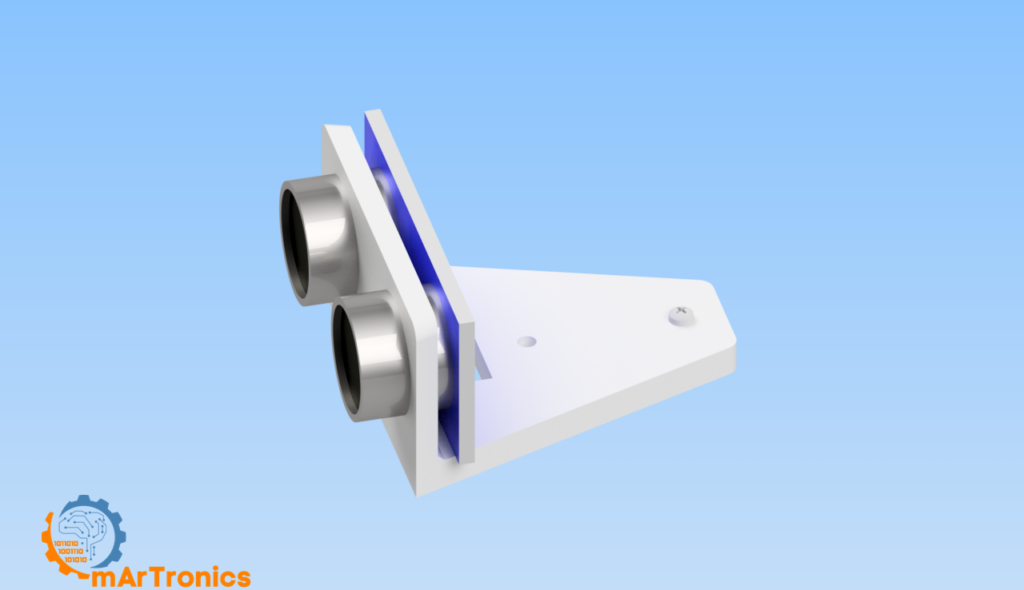
Sensor mount: Design a bracket that snugly holds the HC-SR04 module. Make sure the front of the bracket has openings for both transducers so nothing blocks the ultrasonic cone. The back of the bracket should have a slot or screw hole to attach it directly to the servo horn.
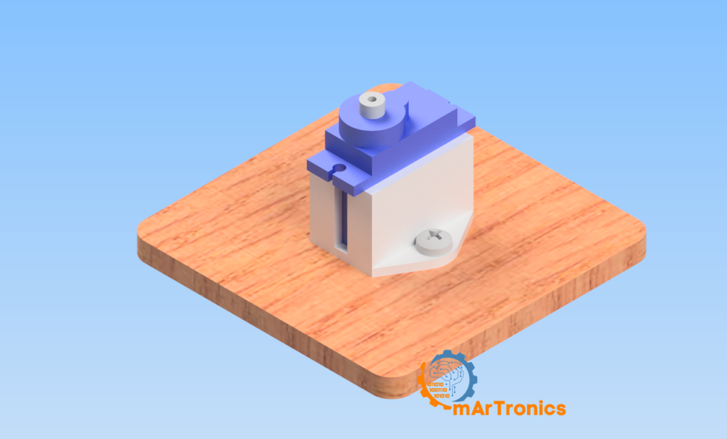
Servo mount: Create a base that holds the servo body firmly in place. Make the base wide and flat enough to sit on a table or bolt it to a platform. Keep the servo horn accessible at the top so the sensor bracket can rotate freely. For design inspiration and general 3D printing guidance, see our introduction to 3D printing and 3D design.
Assembling the Hardware
With your components and optional mounts ready, follow these steps to assemble the hardware.
Step 1 — Mount the sensor: Secure the HC-SR04 in its 3D-printed bracket (or tape it to the servo horn). Make sure nothing covers or blocks either transducer.
Step 2 — Mount the servo: Place the servo motor into its base bracket. If you are not using a printed mount, press the servo body into the breadboard area or secure it to the table with adhesive putty.
Step 3 — Attach sensor to servo: Connect the sensor bracket to the servo horn using the small screw that comes with the servo, or use a snap-fit design. The sensor should rotate smoothly when the servo moves.
Step 4 — Connect the wiring: Follow the wiring table in the next section to connect all components to the Arduino using the breadboard and jumper wires.
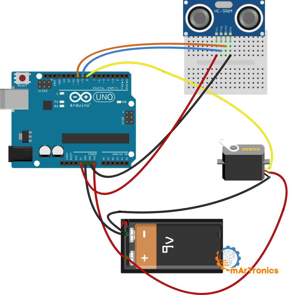
Wiring Diagram and Pin Connections
Fortunately, the wiring for this Arduino radar project is straightforward. Use the table below for the core build. If you are also adding the optional buzzer, include the buzzer row as well. Make sure all components share a common ground connection through the Arduino GND pin.
Core Radar Wiring
| عنصر | Component Pin | دبوس أردوينو | ملحوظات |
|---|---|---|---|
| SG90 Servo | Signal (Orange/Yellow) | Pin 8 | PWM control wire |
| SG90 Servo | VCC (Red) | 5 فولت | Power supply for servo |
| SG90 Servo | GND (Brown/Black) | أرضي | أرضية مشتركة |
| HC-SR04 | VCC | 5 فولت | Sensor power |
| HC-SR04 | أرضي | أرضي | أرضية مشتركة |
| HC-SR04 | TRIG | Pin 9 | Trigger pulse output |
| HC-SR04 | ECHO | Pin 10 | Echo pulse input |
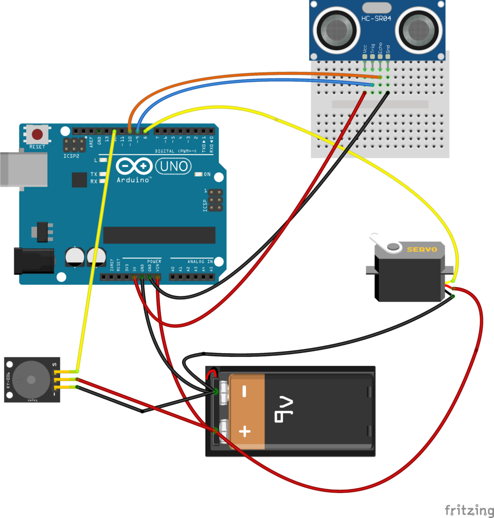
Optional Buzzer Wiring
| عنصر | Component Pin | دبوس أردوينو | ملحوظات |
|---|---|---|---|
| Piezo Buzzer | Positive (+) | Pin 12 | Signal wire for tone output |
| Piezo Buzzer | Negative (−) | أرضي | أرضية مشتركة |
مهم: All GND connections (servo, sensor, buzzer) must connect to the same Arduino GND rail. Using separate ground paths can cause erratic sensor readings or servo jitter. Use the breadboard power rails to distribute 5V and GND cleanly.
Arduino Code: Core Radar Sketch
The Arduino sketch below forms the core of the radar system. It sweeps the servo from 15 to 165 degrees and back, taking a distance measurement at each degree. Every reading is sent over serial in the format angle,distance. so that the Processing sketch (or any serial monitor) can parse it.
/**
 * Arduino Ultrasonic Radar — Core Sketch
 * Author: Omar Draidrya
 * Date: 2024/05/09
 * This code controls a servo motor and measures distance
 * using an HC-SR04 ultrasonic sensor.
 */

#include <Servo.h>

Servo myServo;

const int trigPin = 9;
const int echoPin = 10;

long duration;
int distance;

void setup() {
  pinMode(trigPin, OUTPUT);
  pinMode(echoPin, INPUT);
  Serial.begin(9600);
  myServo.attach(8);
}

void loop() {
  // Forward sweep: 15 to 165 degrees
  for (int i = 15; i <= 165; i++) {
    myServo.write(i);
    delay(30);
    distance = calculateDistance();
    Serial.print(i);
    Serial.print(",");
    Serial.print(distance);
    Serial.print(".");
  }
  // Return sweep: 165 back to 15 degrees
  for (int i = 165; i > 15; i--) {
    myServo.write(i);
    delay(30);
    distance = calculateDistance();
    Serial.print(i);
    Serial.print(",");
    Serial.print(distance);
    Serial.print(".");
  }
}

int calculateDistance() {
  digitalWrite(trigPin, LOW);
  delayMicroseconds(2);
  digitalWrite(trigPin, HIGH);
  delayMicroseconds(10);
  digitalWrite(trigPin, LOW);
  duration = pulseIn(echoPin, HIGH);
  distance = duration * 0.034 / 2;
  return distance;
}
How the Arduino Radar Code Works
Servo sweep logic: Two for loops control the sweep. The first moves the servo from 15 to 165 degrees, and the second returns it from 165 back to 15. The range is 15–165 instead of 0–180 for two reasons. First, most budget servos have dead zones at their travel extremes. Second, the HC-SR04 reads best when aimed away from the mounting base. A 30-millisecond delay between each degree gives the servo time to reach the next position before measurement.
Distance calculation with pulseIn(): Next, the calculateDistance() function sends a 10-microsecond HIGH pulse on the TRIG pin. It then calls pulseIn(echoPin, HIGH). Essentially, this function blocks execution until the ECHO pin goes HIGH and returns the pulse duration in microseconds. In other words, this duration represents the total round-trip travel time of the ultrasonic wave. Multiplying by 0.034 converts microseconds to centimeters, since sound travels about 0.034 cm per microsecond. Dividing by 2 then gives the one-way distance to the object.
Serial Output and Testing
Serial output format: Each reading is sent as angle,distance. — for example, 90,25. means the sensor is pointing at 90 degrees and detected an object at 25 cm. Specifically, the period . acts as a delimiter that tells the Processing sketch where one reading ends and the next begins. You can verify this output by opening the Arduino IDE Serial Monitor at 9600 baud after uploading the sketch.
Testing with Serial Monitor: Before setting up Processing, first upload this sketch. Then open the Serial Monitor (Tools > Serial Monitor), and set the baud rate to 9600. You should see a continuous stream of angle-distance pairs like 15,40.16,38.17,35. flowing across the screen. If you see only zeros or very large numbers, therefore check your wiring and see the Troubleshooting section below.
Optional Upgrade: Adding a Buzzer for Obstacle Alerts
Once the core radar is working, you can then add a piezo buzzer to get an audible warning whenever an object is detected closer than a set threshold. As a result, this turns the radar into a proximity alarm system similar to car parking sensors. Wire the buzzer to pin 12 and GND as shown in the wiring table above, then upload the modified sketch below.
/**
 * Arduino Ultrasonic Radar — Buzzer Upgrade
 * Author: Omar Draidrya
 * Date: 2024/05/09
 * Adds a buzzer alert when an obstacle is within threshold distance.
 */

#include <Servo.h>

Servo myServo;

const int trigPin = 9;
const int echoPin = 10;
const int buzzerPin = 12;
const int alertThreshold = 10; // cm — change this value to adjust sensitivity

long duration;
int distance;

void setup() {
  pinMode(trigPin, OUTPUT);
  pinMode(echoPin, INPUT);
  pinMode(buzzerPin, OUTPUT);
  Serial.begin(9600);
  myServo.attach(8);
}

void loop() {
  for (int i = 15; i <= 165; i++) {
    myServo.write(i);
    delay(30);
    distance = calculateDistance();
    Serial.print(i);
    Serial.print(",");
    Serial.print(distance);
    Serial.print(".");

    if (distance <= alertThreshold) {
      tone(buzzerPin, 2000);
    } else {
      noTone(buzzerPin);
    }
  }
  for (int i = 165; i > 15; i--) {
    myServo.write(i);
    delay(30);
    distance = calculateDistance();
    Serial.print(i);
    Serial.print(",");
    Serial.print(distance);
    Serial.print(".");

    if (distance <= alertThreshold) {
      tone(buzzerPin, 2000);
    } else {
      noTone(buzzerPin);
    }
  }
}

int calculateDistance() {
  digitalWrite(trigPin, LOW);
  delayMicroseconds(2);
  digitalWrite(trigPin, HIGH);
  delayMicroseconds(10);
  digitalWrite(trigPin, LOW);
  duration = pulseIn(echoPin, HIGH);
  distance = duration * 0.034 / 2;
  return distance;
}
How the buzzer works: Essentially, after each distance measurement, the code checks whether the distance is less than or equal to alertThreshold (which defaults to 10 cm). If it is, tone(buzzerPin, 2000) drives the buzzer at 2000 Hz. Otherwise, noTone() silences it. Furthermore, you can change alertThreshold to any value you want. For instance, setting it to 20 cm makes the alarm more sensitive. Conversely, setting it to 5 cm triggers it only for very close objects.
Optional Upgrade: Real-Time Radar Visualization with Processing
The Arduino radar project works perfectly using just the Serial Monitor, but the real visual payoff comes from connecting it to a Processing sketch that draws a live radar screen. Processing is a free, open-source programming environment. Developers designed it for visual and interactive projects. It reads serial data from the Arduino and renders graphics in real time. This makes it the perfect companion tool for this project.
مهم: Nevertheless, the radar system is fully functional without Processing. If you only want to build the hardware and see distance data in the Serial Monitor, you can skip this section entirely.
What the Processing Sketch Does
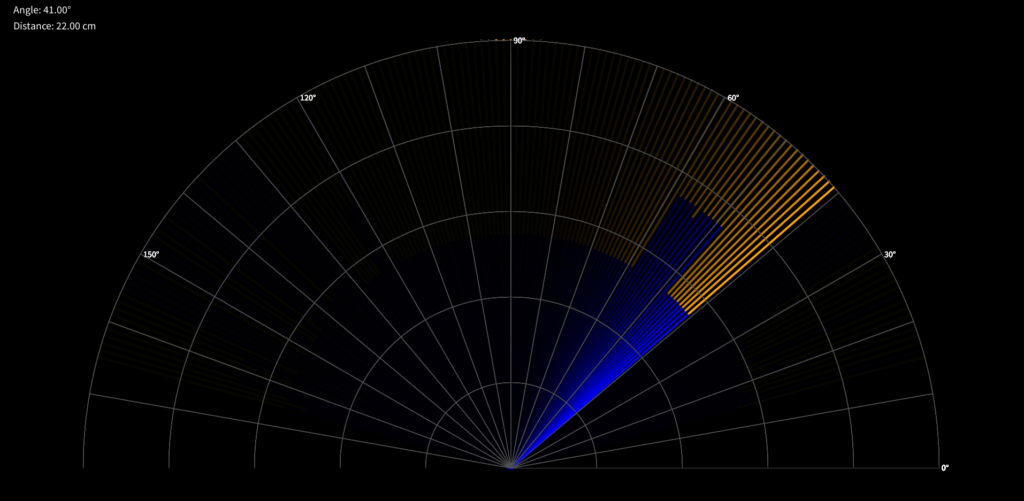
Specifically, the Processing code opens a serial connection to the Arduino at 9600 baud. It reads the incoming angle,distance. data stream, parses each reading, and draws a radar display. As a result, detected objects appear as colored lines within arc rings that represent distance ranges. Additionally, the display shows the current angle and measured distance in a text overlay.
How to Set Up Processing
Step 1: Download and install the Processing IDE from processing.org.
Step 2: Next, close the Arduino IDE Serial Monitor if it is open. Only one application can use the serial port at a time.
Step 3: Then, copy the Processing code below into a new Processing sketch and run it.
Step 4: If the radar screen appears but shows no scan line, you likely need to change the serial port index. In the line String portName = Serial.list()[0];, change the [0] ل [1] أو [2] depending on which port your Arduino is on. You can print Serial.list() to the Processing console to see all available ports.
Processing Radar Code
/**
 * Arduino Radar — Processing Visualization
 * Date: 2024/05/09
 * Reads serial data from Arduino and draws a radar display.
 */

import processing.serial.*;

Serial communicationPort;
String serialData = "";
float scanAngle = 0;
float scanDistance = 0;
int radarRadius = 800;
int maxDistance = 40; // cm

void setup() {
  size(1920, 1080);
  smooth();
  String portName = Serial.list()[0]; // Adjust index if needed
  communicationPort = new Serial(this, portName, 9600);
  communicationPort.bufferUntil('.');
  background(0);
}

void draw() {
  drawRadarBackground();
  if (serialData.length() > 0) {
    parseSerialData();
    drawDetection();
  }
  displayInfo(scanDistance, scanAngle);
}

void drawRadarBackground() {
  pushMatrix();
  translate(width / 2, height - 200);
  noFill();
  stroke(80);
  strokeWeight(1);
  for (int i = 0; i < 5; i++) {
    float r = radarRadius * (i + 1) / 5.0;
    arc(0, 0, r * 2, r * 2, PI, TWO_PI);
  }
  for (int i = 0; i < 180; i += 10) {
    float x = radarRadius * cos(radians(i));
    float y = radarRadius * sin(radians(i));
    line(0, 0, x, -y);
    if (i % 30 == 0) {
      fill(255);
      textSize(16);
      text(i + "°", x + 5, -y + 5);
    }
  }
  popMatrix();
}

void parseSerialData() {
  String[] tokens = serialData.split(",");
  if (tokens.length >= 2) {
    scanAngle = float(tokens[0]);
    scanDistance = float(tokens[1]);
  }
}

void drawDetection() {
  float angle = radians(scanAngle);
  float distance = scanDistance;
  float x = distance * 20;
  float fullX = radarRadius * cos(angle);
  float fullY = radarRadius * sin(angle);

  pushMatrix();
  translate(width / 2, height - 200);
  strokeWeight(4);
  noStroke();
  fill(0, 20);
  rect(-radarRadius, -radarRadius, radarRadius * 2, radarRadius);

  if (distance > 0 && distance <= maxDistance) {
    stroke(0, 0, 255);
    line(0, 0, x * cos(angle), -x * sin(angle));
    stroke(255, 165, 0);
    line(x * cos(angle), -x * sin(angle), fullX, -fullY);
  } else {
    stroke(0, 0, 255);
    line(0, 0, fullX, -fullY);
  }
  popMatrix();
  serialData = "";
}

void displayInfo(float distance, float angle) {
  fill(0);
  noStroke();
  rect(10, 10, 260, 80);
  fill(255);
  textSize(20);
  text("Angle: " + nf(angle, 1, 2) + "°", 30, 30);
  text("Distance: " + nf(distance, 1, 2) + " cm", 30, 60);
}

void serialEvent(Serial p) {
  serialData = p.readStringUntil('.');
  serialData = serialData.substring(0, serialData.length() - 1);
}
Understanding the Serial Data Format
In summary, the Arduino sends data in the exact format angle,distance. — for example, 45,18.. The Processing sketch uses bufferUntil('.') to collect characters until it sees the period delimiter. It then splits the string on the comma to extract the angle and the distance. If the format changes even slightly, the Processing sketch will fail to parse the data. For example, adding a space or changing the delimiter breaks the display. Therefore, always keep the Arduino output and the Processing parser in sync.
Calibration, Accuracy, and Limitations
Once you have the radar running, you will notice that real-world performance is not always as clean as expected. Therefore, understanding these limitations helps you interpret the data correctly and make targeted improvements.
Servo alignment: In particular, most hobby servos are not perfectly calibrated out of the box. Angle 90 on a fresh servo may not point exactly straight ahead. If your radar display seems rotated or offset, simply adjust the sensor bracket on the horn or add a small offset in your code.
Ultrasonic cone width: Furthermore, the HC-SR04 emits sound in a cone roughly 15 degrees wide. Consequently, it cannot distinguish between two objects that are close together within that cone. In addition, the sensor may detect the edge of a large object even when it is not directly ahead.
Reflective and soft surfaces: Generally, hard flat surfaces like walls and boxes produce strong echoes. In contrast, soft fabrics, angled surfaces, and thin objects like chair legs can absorb or deflect the pulse. This causes missed readings or incorrect distances.
Range, Noise, and Sweep Speed
Practical maximum range: Although the HC-SR04 datasheet claims up to 400 cm, reliable readings typically max out around 200 cm. Beyond that, echoes become too weak to detect consistently. For this radar project, accordingly, the default display distance in the Processing sketch is 40 cm. This works well for tabletop demos.
قراءات صاخبة أو متذبذبة: Similarly, occasional spikes in distance readings are normal. Multipath reflections, electrical noise, or lingering echoes from previous pulses often cause these spikes. To fix this, add a short averaging filter in your Arduino code that takes three readings and uses the median value.
Sweep speed versus update rate: Finally, the 30-millisecond delay per degree means a full forward sweep takes about 4.5 seconds. Reducing the delay makes the sweep faster. However, the servo has less time to settle, which can introduce vibration and inaccurate readings. Increasing the delay makes measurements more stable but slows the radar refresh rate.
استكشاف الأخطاء وإصلاحها في المشاكل الشائعة
If something is not working as expected, first work through this checklist before making hardware changes.
Servo not moving: Check that the servo signal wire is on pin 8. Also verify that VCC and GND connect to the Arduino 5V and GND. Try a simple sweep sketch from the Arduino Servo examples. This helps isolate whether the issue is the servo or the radar code.
HC-SR04 always reads 0 or maximum distance: First, verify that TRIG is on pin 9 and ECHO is on pin 10. Also, make sure the sensor runs on 5V (not 3.3V). Check that the transducers are not obstructed by the mount. Then, point the sensor at a flat wall 20 cm away and check the Serial Monitor.
Noisy or jumping distance values: First, ensure all ground connections are common. In addition, long jumper wires can pick up electrical noise. If readings still fluctuate, add a 10 uF capacitor between the sensor VCC and GND pins. This stabilizes the power supply.
Buzzer always on or never triggers: First, make sure the buzzer is wired to pin 12. Check the alertThreshold value in the code. Consequently, if the sensor reads incorrect distances (see above), the buzzer logic will also behave incorrectly. Therefore, fix the sensor readings first.
Processing and Serial Troubleshooting
Processing not connecting or showing a blank screen: Close the Arduino Serial Monitor before running the Processing sketch. Only one program can use the serial port at a time. If the sketch runs but the radar stays blank, change the port index in Serial.list()[0] ل [1] أو [2]. To find the right port, print Serial.list() to the Processing console.
Serial format mismatch: The Processing sketch expects the exact format angle,distance. with no spaces. If you modify the Arduino Serial.print() statements, the Processing parser will break. For example, adding units or extra delimiters causes parsing failures. Keep both sketches in sync.
Power issues or erratic behavior when servo moves: Keep in mind that the SG90 servo can draw up to 500 mA under load. If the Arduino runs only on USB power, the servo may cause voltage drops. These drops can reset the Arduino or corrupt sensor readings. To fix this, power the servo from an external 5V supply. Make sure it shares a common ground with the Arduino.
الأسئلة الشائعة
What is an Arduino radar project?
An Arduino radar project uses an ultrasonic sensor mounted on a servo motor. The servo scans the area ahead, measuring the distance to objects at each angle. The Arduino sends the data to a computer, which displays it as a radar-style sweep on screen. As a result, it is one of the most popular intermediate Arduino projects.
Can I use a different ultrasonic sensor instead of the HC-SR04?
Yes. Yes. The HC-SR04 is the most popular option because it is cheap and reliable. However, you can substitute it with sensors like the US-015 or JSN-SR04T. Just make sure the replacement uses the same TRIG/ECHO interface. If it uses a different protocol (such as I2C or UART), you must modify the Arduino code.
What is the maximum range of the HC-SR04 radar?
The HC-SR04 datasheet states a maximum range of 400 cm (about 13 feet). In practice, however, reliable readings usually top out around 200 cm. For this project, the Processing display defaults to 40 cm. This range works well for tabletop demonstrations. You can increase maxDistance in the Processing sketch to display a wider range.
Do I need a 3D printer to build this project?
No. The 3D-printed mounts make the build sturdier and more presentable. However, you can also attach the HC-SR04 to the servo horn using hot glue, tape, zip ties, or cardboard. In fact, many makers complete this project entirely on a breadboard.
Why does the servo sweep from 15 to 165 degrees instead of 0 to 180?
Most budget servos have dead zones or reduced torque near 0 and 180 degrees. Limiting the sweep to 15–165 degrees keeps the servo in its reliable range. Additionally, it prevents the sensor from pointing backward toward its own mounting base, which would produce false readings.
Can I use an Arduino Nano or Mega instead of the Uno?
Yes. The code is compatible with the Arduino Nano, Mega, and most other AVR-based Arduino boards. Just make sure the pin numbers in the code match the pins on your board. Also confirm that the board provides 5V for the sensor and servo.
How do I change the buzzer activation distance?
In the buzzer sketch, find the line const int alertThreshold = 10; and change the value to whatever distance (in centimeters) you want. For example, setting it to 25 means the buzzer will activate whenever an object is within 25 cm.
Why is my Processing radar screen blank even though the sketch runs?
In most cases, this means Processing connects to the wrong serial port. Print Serial.list() in the Processing console, find the port your Arduino uses (such as COM3 on Windows or /dev/ttyUSB0 on Linux). Then update the index in Serial.list()[0]. Also, close the Arduino Serial Monitor first. Two programs cannot share the same serial port.
Can this radar detect people or animals?
Yes, to some extent. The HC-SR04 detects any object that reflects sound waves. This includes people, pets, and furniture. However, thin or soft objects like a cat’s fur at a distance may not reflect a strong echo. For reliable human detection at longer ranges, consider a microwave radar module or a LiDAR sensor.
How accurate is the distance measurement?
Under ideal conditions, the HC-SR04 has a rated accuracy of about 3 mm. Ideal conditions include a flat surface, room temperature, and no interference. In real-world use, expect accuracy within 1 to 2 cm for distances under 100 cm. Accuracy decreases at longer ranges and with angled or soft surfaces.
Related Resources
Use the links below to deepen your understanding of the components used in this project. In addition, they can help you find your next build.
- شرح مفصل لمستشعر المسافة بالموجات فوق الصوتية HC-SR04 باستخدام أردوينو: التوصيلات والبرمجة — Covers the HC-SR04 in detail, including wiring, code, and common pitfalls.
- دليل التحكم في محركات المؤازرة باستخدام أردوينو: SG90، PWM، وPCA9685 — Everything about driving servo motors with Arduino, including the PCA9685 driver for multi-servo projects.
- Arduino Programming Basics: Complete Beginner Guide — If you are new to Arduino code, start here for setup(), loop(), variables, and the Serial Monitor.
- ما هو أردوينو؟ — A beginner-friendly overview of the Arduino platform, boards, and ecosystem.
- مقدمة في الطباعة ثلاثية الأبعاد والتصميم ثلاثي الأبعاد باستخدام برنامج Inventor — Learn how to design and print your own parts for electronics projects.
- Building an Obstacle-Avoiding Robot Car with Arduino — Another project that uses the HC-SR04 and a servo for autonomous navigation.
- Building a Line Following Robot with KY-033 Sensors — A beginner robotics project to try after completing the radar.
- DIY 6-DOF Robotic Arm — 3D Print, Wire, and Program — An advanced multi-servo project that builds on the servo skills used in this tutorial.
Conclusion and Next Steps
In conclusion, you have now built a complete Arduino radar system using an HC-SR04 ultrasonic sensor and a servo motor. Along the way, you learned how ultrasonic time-of-flight measurement works and how to sweep a sensor with a servo. You also learned how to format serial data and optionally add a buzzer or a Processing visualization. You will use these skills — sensor reading, motor control, serial communication, and data display — in nearly every robotics and embedded systems project you tackle next.
To take this project further, consider increasing the sweep speed. You could also add a median filter for smoother readings. Another option is to replace the HC-SR04 with a VL53L0X laser sensor for millimeter-level accuracy. Alternatively, use a stepper motor instead of a servo for full 360-degree scanning. For a completely different challenge, try building an سيارة روبوتية تتجنب العوائق that uses the same ultrasonic sensor and servo combo to navigate autonomously. Explore more Arduino and robotics tutorials on the OmArTronics homepage.